International Journal of Scientific & Engineering Research, Volume 4, Issue 12, December-2013 877
ISSN 2229-5518
Optimal Reactive Power Insertion & Allocation To The Iraqi Super Grid 400 Kv
Network Applying Genetic Algorithm Technology
Assist. Prof. Mohammed Sabri A. Raheem
ABSTRACT: The aim of this paper is to find the optimal location and the reactive power needed to be inserted in the 400 Kv super grid Iraqi network , so as to reduce the losses in the network and reaching the optimum power flow . A Genetic Algorithm calculation method is applied and the Optimum Power Flow program is applied to calculate and find the power flow distribution in the network . A comparison can be set to find the change in the network parameters before and after allocation of the reactive power injection nodes , also noticing the improvement in the power factor of the power flows in the T.L's .
KEY WORDS: Power factor improvement, Participation factor, Genetic Algorithm, Switching capacitor
Type ,Optimum Power Flow Program , Iraqi 400 Kv network .
1. INTRODUCTION
During the peak load periods especially in winter
and summer as a result of increasing needs for inductive power due to high inductive loading and to improve power factor for the transmission system and to avoid the resultant losses accused by the current for long distances. For this purpose, the use of capacitors in system with special circuit breakers to convey the capacitive
current will be necessary [1, 2].
B) Inserting capacitor in work or out of work (such as 20MVAR) that will cause a large sudden change in voltage magnitude.
C)In transformers 132/33/11 kV, it is noted that output power from the transformer must be greater than the value of the required capacitor to improve the voltage and avoiding transformer working on leading p. f. [3] .
D) Adding capacitor to the tertiary on 11 kV side
IJSER
Locating circuit breakers to the capacitor is not

possible unless convey the same capacitive current rating or higher value from it.
Insertion of capacitors to the transmission line network is possible in self-transformers
400/132/11 KV.

On 11kv side, we use it is because of the increase in inductive power on 132kv side. Therefore, we can see the increase in voltage on 132kv side clearly.
The following notes are noted on connection of capacitors in transmission lines
A) Avoid switching off transformer and capacitor in work because of resonance phenomenon in which the impedance of XC and XL are equal and occurs a short circuit on coils of transformers and damage them and also avoid switch on transformer again with a connected capacitor because of the same phenomenon.

Assist. Prof. Mohamed Sabri A.Raheem is at the lecturing staff of the electrical & electronics techniques college , Foundation of Technical Education, Baghdad , Iraq. The majority of research works were at the field of Protection, distribution,reliability ,& Var compensation of electric power systems. Contact address e.mail (mohsab2008@gmail.com)
in self-transformers will increase the current on
132 kV side.
2. POWER FACTOR CORRECTION
Capacitors offer a means of improving system
power factor and helping to correct the above conditions by reducing the reactive kilovar load carried by the utility system [4, 5].

3. CAPACITORS OR VOLTAGE REGULATORS
Shunt capacitors provide some voltage rise
and can do so at a lower cost than a line regulator. Sample calculations are shown in the following sections.
However, for some load conditions, the voltage rise offered by capacitors may be excessive and cause problems for customers’ connected equipment. Higher cost regulators offer a means for maintaining more constant system voltage. The combination of regulators and capacitors provides the best of both worlds [6, 9].

4. OPTIMAL CAPACITOR PLACEMENT
Before determining the capacitor location,
using exciting power flow methods (Newton
_Raphson methods) to study the need for such operation.
Bus participation factors are used to select the candidate buses for the subsequent VAR source placement. The buses with higher participation factors are selected first, and they are considered in the second stage where the genetic algorithm
IJSER © 2013 http://www.ijser.org
International Journal of Scientific & Engineering Research, Volume 4, Issue 12, December-2013 878
ISSN 2229-5518
technique is employed to optimize the location, and size of VAR sources [4].
5. GENETIC ALGORITHM OPTIMIZATION
To solve the optimization problem,
formulated in (A) the genetic algorithm was used, a technique inspired by the principle of evolution. The description of GA theory can be found in [7].
GA uses a “Chromosomal” representation which requires the solution to be coded as a GA used in this paper is as follows:
First, the initial population of Ns randomly constructed solutions (strings) is generated. Within this population new solutions are obtained during the genetic Cycle using crossover and mutation operators. Crossover produces a new finite length string. The basic structure solution (off spring) forms a randomly selected pair of parent solutions providing the inheritance of some basic properties of the parents in the offspring.
incrementing or decrementing by 1 the randomly chosen number from this string with some given probability [12].
6. A POWER NETWORK CASE STUDY
A 10- generator case (the system of Iraq) with 22 bus bars is taken to illustrate the proposed algorithm to correction power factor problem.
As in the previous section the same procedures will be computed to get the reduced total cost.
Figure(1) down below presents the schematic of 22 bus transmission system.
The Newton ـ�ـ Raphson, of the system, and the load flow the system before placing the capacitors are presented in Tables (1)
To improve power factor, the method of
Participation factor is performed by computing the Jacobian Matrix reduction JR to analyze the stability of the voltage. This can be made by computing the eigen values and eigenvectors for JR matrix, where the values of eigen values give a proximate for the voltage instability at the load
IJSER
Mutation results in slight changes in the
offspring structure and maintains diversity of solutions [8, 10].
Each new solution is decoded and its objective function (fitness) values are estimated.
These values are a measure of the quality which is used to compare different solutions. The comparison is fulfilled by a selection procedure that decides which solution is better: the newly obtained one or the worst solution in the population. The better solution joins the population and the worse one is discarded. If the population contains equivalent solutions following selection, redundancies are eliminated and the population size decreases. After Nrep repetitions of the crossover-selection sequence, new random constructed solutions are generated to replenish the shrunken population, and a new genetic cycle is started. The GA is terminated after Nc genetic cycles. The final population contains the best solution achieved [11].
The crossover operator is aimed at producing a new solution (string) which inherits some properties of both parent solutions by combining parts of their strings. A two-point (fragment) crossover is adopted in which elements belonging to the fragment defined by two randomly chosen crossover sites are copied from the first parent and elements located out of the fragment, from the second parent. Mutation provides slight changes in the string by
level, and from this we can determine the
Participation Factor for the buses of the system, and the buses that have the minimum eigen values are selected and large PF values are used to inject the capacitors in the buses.
Tables (2) below present the results buses and the Participation factor for these buses:
From the results of the participation factor, the
10 candidate locations in the system are selected for placing the capacitors, (Table (3)).
After the best candidate buses are obtained, the next step is to get the optimal sizes for the capacitors to place them in these buses, this is done by using the Genetic Algorithm (GA). And to achieve this target, we need to building an initial population and getting the fitness function and determined the number of generations. At initial, random population are selected and the encoding of the chromosomes of the population use integer values (because each chromosome will present the number of capacitors that will be injected to system). Each of chromosome is added to the buses data array to the field of Qsht (which present the field of capacitors) and compute the power losses for the system.
The value of power losses will be multiplied by the cost of energy and will be added to the price of capacitors and their maintenance to give the fitness function. So, to
IJSER © 2013 http://www.ijser.org
International Journal of Scientific & Engineering Research, Volume 4, Issue 12, December-2013 879
ISSN 2229-5518
get the perfect power factor we must get the best chromosome that has the minimum fitness function.
Fit. Fun.= Pd /  (Pd ^2+ (Qd -Qsh ) 2) Pd = load active power (MW)
Qd = load reactive power (MVAR)
Qsh =added reactive power (MVAR)
Table (3) presents the location of candidate
capacitors and their optimal sizes which are obtained from the GA and Tables (4), (5) below present the final results to get the reduced total generation costs.
8 . Conclusions :
On comparing the Iraqi network data presented
in tables (1),(5),for the same load data , there is an improvement in the generating system power factor,also reduction in the generated power. Sgen. =4618.651+j1026.448 Mva before correc. Sgen. =3173.154+j600.2690 Mva after correc. and the injected reactive power is of 80 Mvar.
at the selected network nodes .This will helps greatly improving the total network operating conditions.
[6] M. E. Baran and F. F. Wu, “Optimal capacitor Placement on Radial Distribution Feeders,” IEEE Trans. on Power Delivery, vol.
4, no. 1, pp. 725-734 , 1989 .
[7] G. Boon and H. D. Chiang, “Optimal Capacitor Placement in Distribution Systems by Genetic Algorithm,” Electrical Power & Energy Systems, vol. 15, no. 3, pp. 155–162, 1993.
[8] S. Sundhararajan and A. Pahwa, “Optimal Selection of Capacitors For Radial Distribution Systems Using a Genetic Algorithm", IEEE Trans. On Power systems
, vol. 9, no. 3, pp. 1499–1505, 1994.
[9] A. M. Sharaf and S. T. Ibrahim, “Optimal Capacitor Placement in Distribution networks," Electric Power System Research, no. 37, pp.
181–187, 1996.
[10] K. N. Mui, H. D. Chiang, and G. Darling, “Capacitor Placement, Replacement & Control in Large-Scale Unbalanced Distribution
Systems by a GA-Based Two stage Algorithm " , IEEE Trans. on Power Systems, Vol. 12 , no. 3 . pp. 1160-1166 , 1997.
[11] A. Kalyuzhny, G. Levitin, D. Elmakis, H.
IJSEBen-Haim, andRZ. Zisman, " Optimum capacitor

9. REFERENCES
[1] Hirst, E., “U.S. Transmission Capacity:
Present Status and Future Prospect”, Edison Electric Institute and the Office of Electric Transmission and Distribution, U.S. Department of Energy, Aug. 2004
[2] Abraham, S., “National Transmission Grid Study”, U.S. Department of Energy , May 2002 [3] “Principles for Efficient and Reliable Reactive Power Supply and Consumption”,
Staff Report Docket No. A-D-05-1-000 Federal

Energy Regulatory Commission [FERC], Feb. 4
, 2005
[4] M. Ponnavaikko and K. S. Prakasa Rao, “Optimal Choice of Fixed and Switched
Shunt Capacitors on Radial Distributors by the
Method of Local variations " ,” IEEE Trans. on PAS., vol. PAS-102, no.6,pp.1607-1615, 1983. [5] M. Kaplan, “Optimization of Number, Location, Size, Control Type, and Control Settings of Shunt Capacitors on Radial Distribution Feeders”, IEEE Trans. On Power Apparatus & Systems., vol. PAS-103, no. 9, pp.
2659–2665, 1984 .
Allocation in Distribution Systems Under
Capacitor Switching Constraints ",Proceedings on the 1st Mediterranean Conference on Power Generation, Transmission and Distribution, Nicosia, Cyprus, Nov. 16–17, 1998.
[12] A.Shenkman ,“Energy Loss computation by Using Statistical Techniques,” IEEE Transactions on Power Delivery , Vol. 1, No.1 ,pp-254-258 ,
Jan 1990
[13] D. Goldberg, "Genetic Algorithms in
Search, Optimization and Machine Learning "
., MA: Addison Wesley, 1989
IJSER © 2013 http://www.ijser.org
International Journal of Scientific & Engineering Research, Volume 4, Issue 12, December-2013 880
ISSN 2229-5518
Table (1) Power Flow Solution By Newton- Raphson before placing the capacitors
Maximum Power Mismatch = 6.38099e-007
No. of Iterations = 10
No reactive power injections at the nodes
Table (3) Switching Capacitors allocations and Their optimal Sizes
Table (4) Optimal Dispatch of Generation and
Lambda of The System
Table (2) Participation factor for The Selected Buses
Bus No. | Participation Factor |
2 | 0.0025 |
6 | 0.1344 |
8 | 0.0025 |
9 | 0.1344 |
10 | 0.0836 |
11 | 0.0374 |
13 | 0.0836 |
15 | 0.1514 |
16 | 0.1623 |
17 | 0.1500 |
19 | 0.0374 |
22 | 0.3115 |
IJSER © 2013 http://www.ijser.org
International Journal of Scientific & Engineering Research, Volume 4, Issue 12, December-2013 881
ISSN 2229-5518
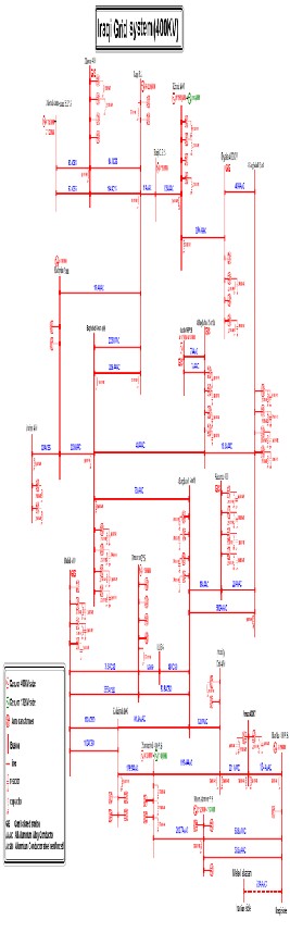
Table (5) Power Flow Solution by Newton- Raphson after placing the capacitors
Maximum Power Mismatch = 7.87172e-007
No. of Iterations = 10
After Reactive Power Injection & their locations
IJSER
Figure(1) The Iraqi 400 Kv super grid network
IJSER © 2013 http://www.ijser.org