International Journal of Scientific & Engineering Research, Volume 4, Issue 4, April-2013 1520
ISSN 2229-5518
Open Loop Control of a Novel Power Converter for
FuelCell assisted Photovoltaic Power Systems
S. Ramya, A.Napolean
Abstract— A novel DC-DC converter is proposed in the work carried out powered from multiple sources such as PV and Fuel Cell while the Battery is used as the Back-Up source.The power conversion circuit consists of less number of active power switches with associated passive components. By adjusting the duty-ratio of the active power switch, the power sharing between sources as well as the output voltage regulation can be made.According to various situations, the operational states of the proposed converter can be divided into three states based on battery utilization .In order to ensure that the system operates with high efficiency, this paper proposes a power management control scheme, which controls the bidirectional converter operating under boost mode according to the operation condition of the PV/Fuel Cell, so that the battery can be charged or discharged. The system performance under different solar Irradiance has been verified by carrying out simulation studies us- ing a load demand of 2.5 KW.The integration of the hybrid renewable power system is implemented and simulated using MATLAB/SIMULINK.
Index Terms— Alternative energy, DC-DC Converter,Multiple Sources,Power System
—————————— ——————————
he ever increasing energy consumption, the soaring cost and the exhaustible nature of fossil fuel, and the worsening global environment have created increased interest in green [renewable and/or fuel celll (FC)-based ener- gy sources]. Renewable energy sources like Solar and Fuel Cells have always been due to their clean energy production, the most promising but challenging and thus interesting tech-
nologies for power generation[1].
In recent years, a lot of research studies in renewable sources like solar cells, fuel cells and wind energy are being done to improve their efficiency, performance, materials and at the same time to reduce their cost for implementation. Also lately, many research works report solar cells and fuel cells with higher efficiency and reliability. These improvements in renewable energy sources in turn put new challenges to de- signing power electronics incorporated with the renewable sources.
Batteries are usually taken as storage mechanism for smoothing output power, improving startup transitions and dynamic characteristics, and enhancing the peak power ca- pacity [2]. Combining the photovoltaic generation with Fuel Cell , the instability of an output characteristic each other was compensated. Combining such energy source introduces a PV/Fuel Cell/Battery hybrid power system. Nevertheless, be- cause different alternative energy sources can complement each other to some extent,multisource hybrid alternative ener- gy systems (with proper control) have great potential to pro- vide higher quality and more reliable power to customers than a system based on a single resource.[3]. Because of this feature,
______ _ _ _ _ _ _ _ _ _ _ _ _ _
S.Ramya ,P.G Scholar, Department of Electronics and Communication
Engineering,V.S.B Engineering College,karur,India.
e-mail:rmyselvarajan@gmail.com.
A.Napolean, Associate Professor, Department of Electronics and Commu- nication Engineering,V.S.B Engineering College,karur,India.
e-mail:nepojustin@gmail.com.
hybrid energy systems have caught worldwide research at- tention .
In general, a power electronic converter is supplied from a power source and provides the required voltage or current level to the loads. However, for some practical applications of renewable powers and battery systems, the load may not be powered from single source but from different kinds of power sources specified by dissimilar voltage, current, and power ratings[4].In Many Hybrid Power Systems with various Power Electronic Converters have been proposed in the literature up to now. However, the main shortcomings of these integrating methods are complex system topology, high count of devices, high power losses, expensive cost, and large size.
In [5] three multi input converters are proposed based on structure of the DC-DC Boost Converter. The DC–DC Boost Converter in [6] is useful for combining several Energy sources whose power capacity or voltage levels are different. The Multi-input DC–DC Converter proposed has the capabil- ity of operating in different Converter topologies (Buck, Boost, and Buck–Boost) in addition to its Bidirectional operation and positive output voltage without any additional transformer. Further, phase-shift control method is used to manage the power flow among the three ports in addition to soft switch- ing for all switches over a wide input range.Although the cir- cuit efficiency is greatly developed, the converter does not provide bidirectional functionality and is not able to boost the input voltage to a higher level.
Moreover, the summation of duty ratios should be greater than one and the two input voltages should be in the same level in the dual-power-supply operation state. In [7] power control strategies designed manage the charge balance of the battery in order to regulate the output voltage. The proposed power converter is capable of converting power from multiple sources to the load. The sources deliver power to the load al- ternatively by switching the active power switch on and off.
IJSER © 20 13 http://www.ijser.org
International Journal of Scientific & Engineering Research, Volume 4, Issue 4, April-2013 1521
ISSN 2229-5518
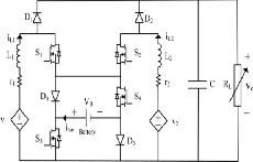
The power conversion circuit of the single switch dual-source three-port dc-to-dc converter is shown in Fig.1. The proposed converter Interfaces two Input power sources v1 and v2 and a battery as the storage element In the proposed circuit, two Inductors L1 and L2 make the Input power ports as two current type sources.
Fig.1. Structure Of the Proposed Converter
It results in drawing smooth currents from the sources. RL is the load resistance and switches S1 – S4 are the main control- lable element that controls the power flow of the hybrid power system. The d1 – d4 are the duty ratios controlling the switches S1 – S4 respectively. The diodes D1 and D2 conducts in complementary manner with switches S1 and S2. Turning ON S3 and S4, makes D3 and D4 to reverse bias by the Vbat. On the other hand, turn – OFF state of these switches makes diodes D3 and D4 able to conduct Input currents iL1 and iL2. The steady states and dynamic behavior of the converter is
observed in Continuous Current Mode (CCM).
Utilization state of the battery defines three power operation modes of the converter. The assumptions for the operation modes are considered by utilizing sawtooth carrier wave- form for S1 – S4 and considering d3, d4< min (d1,d2) in battery charge or discharge mode. d1 is assumed to be less than d2 in order to simplify the operation mode investigation.
Basic operation mode which takes place in the conditions that the summation of the PV and Fuel Cell powers can completely supply the load, without battery existence. Here d1 is used to regulate PV source and d2 is utilized to regulate output voltage.
This mode takes place in the conditions that summation of the Fuel Cell and PV powers can regulate the output voltage as like as first operation mode, while the battery is needed to be charged. In this mode d1 and d2 regulates power of the
input sources, while d3 is utilized to regulate output voltage
through battery charging by the extra –generated power.
This mode takes place in the conditions that the output volt- age cannot be regulated because summation of Fuel Cell and
PV cannot completely supply the load and vBatt.Min < vBatt
the battery discharging is accomplished. Here, d1 and d2 regu-
lates powers of the input sources, while d4 is utilized to regu- late output voltage through battery discharging.
The Evaluation of the performance of the proposed converter is done by simulating all the three operation modes by MATLAB/SIMULINK software. The simulation is done setting
r1 = r2 = 0.4 Ω , L1 = L2 = 6mH,C=200µF =20KHZ.RL with
average power of 2.5KW is supplied at the dc link in the pro-
posed system. The dc-link voltage of the converter is regulated
at vo=350V which is a desired condition.Power of input
sources and Load characteristics are discussed below for three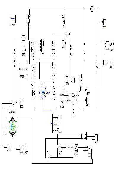
modes.
IJSER © 20 13 http://www.ijser.org
International Journal of Scientific & Engineering Research, Volume 4, Issue 4, April-2013 1522
ISSN 2229-5518
Fig.2. Simulink Diagram
In this stage(S=750 W/m2), the load power required is PL = 2.5
KW (RL = 50 Ω), while the maximum available PV power is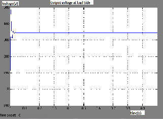
Ppv=1.7 KW and there is no need to charge the Battery.
Fig.3. Output Voltage at load side for mode 1
First, second, third and fourth duty ratios are set as d1=0.7, d2=0.75,d3=0 and d4=1. By setting d3 = 0 and d4 = 1, which re- sult the battery power to be set on zero value. The FC current is regulated by d1, which shows IL1 =3.9A. The PV current is regulated by d2, which shows IL2 =10.5A .The required load voltage is maintained for its entire operating time.
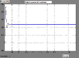
Fig.4. Output Power at load side for mode 1
In this stage, the sun irradiation level increase to S =1000W/m2, while the load power remains constant at PL = 2.5 KW.In this condition, battery remains in charging due to increase in sun irradiation level. The FC current is regulated on IL1 = 6.5 A with
duty ratio d = 0.73, while the maximum power of the PV source is tracked with regulating the PV current at IL2 =15.72 A and adjusting the first duty ratio at d1 = 0.79. Moreover, con- trolling the third and fourth duty ratios at d3 = 0.45 and d4 = 0,
respectively, results in providing the charging power of the
battery in addition to regulating the output voltage .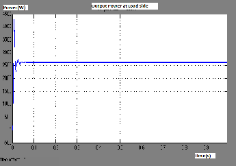
Fig.5. Output Power at load side for mode 2
This stage occurs in a condition that solar power decreased to certain value in which (S=500W/m2), in which the load re-
quires PL = 2.5 KW and the PV power is simultaneously de- creased into Ppv =0.45KW.From the maximum deliverable pow-
er of the PV, it is obviously understood that the PV is not able
to completely supply the power deficiency. Thus, the remain- ing power should be supplied by the battery. Regulating its
current at I L1= = 5.3A and adjusting the first duty ratio at d1 =
0.71, the maximum power of is delivered at I L2 = 15.72A. Ad-
justing the second duty ratio at d2 = 0.73 and controlling the
third and fourth duty ratios at d3 = 1 and d4 = 0.4 results in discharging the battery.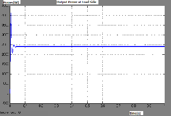
Fig.6. Output Power at load side for mode 3
From the results of three operating mode,it is observed that the converter maintains a constant output irrespective of change in solar irradiance and fuel cell availability.The control signals are given to the four switches according to which the
IJSER © 20 13 http://www.ijser.org
International Journal of Scientific & Engineering Research, Volume 4, Issue 4, April-2013 1523
ISSN 2229-5518
operation modes are selected.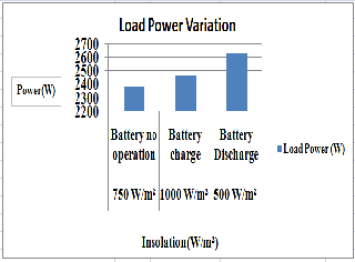
Fig.7. Comparison Of Load power For three modes
A complete description of the hybrid system has been present- ed along with its detailed simulation results showing satisfac- tory performance of the PV/Fuel Cell/Battery system. The properties of charging and discharging are simultaneously obtained in the proposed converter for reducing the corre- sponding installed capacity to further save the cost of system purchasing and power supply.The new converter topology provides designers with an alternative choice to convert a power generator with an energy storage mechanism efficient- ly, and it can also be applied easily to various clean power sources due to the flexible selection of operational states.
The future work will be to design the proposed hybrid system integrating with Wind and Also, the system has to be extend- ed to higher ratings and solve for the synchronization issues.
[1] Matsuo H, Lin W, Kurokawa F, Shigemizu T. and Watanabe N. “Characteristics of the multiple-input DC–DC converter”,IEEE Transactions on Power Electronics, vol. 51, no. 3, pp. 625–631.May
2004
[2] D. B. Nelson, M. H. Nehrir, and C. Wang, “Unit sizing and cost anal- ysis of stand-alone hybrid Wind/PV/fuel cell systems,” Renewable En- ergy, vol. 31, no. 10, pp. 1641–1656, Aug. 2006.
[3] Duarte J. L, Hendrix M. and Simoes M. G. “Three-port bidirectional converter for hybrid fuel cell systems”,IEEE Transactions on Power Electronics ,vol. 22, no. 2, pp. 480–487,May 2009
[4] Kwasinski R. “Identification of feasible topologies for multiple-input
DC–DC converters”, IEEE Transactions on Power Electronics, vol. 24, no. 3, pp. 856– 861, . May 2010
[5] Chen Y. M, Liu Y. Ch, Hung S. C. and Cheng C. S.”Multi-input in- verter for grid-connected hybrid PV/Wind power system”,IEEE Transactions on Power Electronics, vol. 22, no. 3, pp. 1070–1077,April
2007
[6] Sarhangzadeh M, Hosseini S. H, Sharifian M. B. B. and Gharehpetian
G. B.”Multi-input direct DC–AC converter with high frequency link for clean power generation systems”,IEEE Transactions on Power Electronics, vol. 26, no. 6, pp. 1777–1789. May 2011
[7] Farzam Nejabatkhah, Saeed Danyali, Seyed Hossein Hossein,”Modeling
and Control of a New Three-Input DC–DC Boost Converter for Hybrid
PV/FC/Battery Power System” , IEEE Transactions on Power Electronics,
vol. 27, no. 5,May 2012
IJSER © 20 13 http://www.ijser.org