International Journal of Scientific & Engineering Research, Volume 2, Issue 12, December-2011 1
ISSN 2229-5518
OSD: A Source Level Bug Localization Technique Incorporating Control Flow and State Information in Object Oriented Program
Partha Pratim Ray
Abstract— Bug localization in object oriented program has always been an important issue in softeware engineering. In this paper, I propose a source level bug localization technique for object oriented embedded programs. My proposed technique, presents the idea of debugging an object oriented program in class level, incorporating the object state information into the Class Dependence Graph (ClDG). Given a program (having buggy statement) and an input that fails and others pass, my approach uses concrete as well as symbolic execution to synthesize the passing inputs that marginally from the failing input in their control flow behavior. A comparison of the execution traces of the failing input and the passing input provides necessary clues to the root-cause of the failure. A state trace difference, regarding the respective nodes of the ClDG is obtained, which leads to detect the bug in the program.
Index Terms— Bug, ClDG, Embedded software, Object oriented program, Object state, UML.
—————————— ——————————
1 INTRODUCTION
ROM the last few years embedded systems have estab- lished itself as unavoidable criteria in human society. Due to its low code size and less complexity embedded systems
are being implemented in the most sophisticated and critical applications. With this advent of havoc implication of em bedded systems, the whole science community is now moving towards object oriented methods to fulfill the excessive need of these systems. The power of handling complexity is the added advantage to the object oriented technologies that ena- ble them to compete other traditional techniques like as pro- cedural approach.
Debugging denotes the process of detecting root causes of unexpected observable behavior in programs (such as a pro- gram crash, an unexpected output value being produced or an assertion violation). Debugging program errors is a difficult process, and often takes a significant fraction of the time in the program development stage. Even today, debugging remains much of a manual activity, with the actual debugging time de- pendent on the size and complexity of the program being de- bugged, the nature of manifestation of the bug and the level of familiarity and expertise of the programmer. The standard prac- tice of debugging till date in the software community is to ma- nually inspect the execution trace exhibiting the bug inside a debugger and try and locate the error cause(s) from an observed error.
In the past decade, there have been several attempts to au- tomate the debugging activity by fully automated or semi automated formal analysis of the program and/or the failed execution trace for software programs. These methods, in spite of rich theoretical foundations and promising automated bug finding capabilities, have found a low degree of acceptance and
————————————————
Partha Pratim Ray is an Assistant Professor in the Department of Compu- terScience and Engineering in Surendra Institute of Engineering and Management, Dhukuria, P.O. New Chamta, P.S. Matigara, Siliguri, Dar- jeeling - 734009, West Bengal, India.
E-mail: parthapratimray @hotmail.com
penetration in the research and industrial community till date. The main challenge is to develop a scalable solution that can handle softwares of sizeable complexity and pin-point the root cause(s) of an observed error with a high level of accu- racy.
The software needs to undergo a very crucial stage of its life cycle; debugging process. Whenever a program behaves un-expectedly thus producing wrong output is liable to be called a buggy program. In effect to remove the bug from the program the debugging methodology should be very stable one. Though different techniques are already available to de- bug an object oriented program, they all are not very suitable for the targeted problem, such as having a prominent state chart in form of UML. In this type of cases I need to imply a new technique that adds object state information of the class being executed, into the ClDG. This helps in knowing the root cause of the bug, introduced in the program under execution.
The Class Dependence Graph (ClDG) represents the control and data dependencies within a class [1]. For a given class, the ClDG consists of a set of program dependence graphs (PDGs) [2] with additional edges to represent inter-procedural control and data dependences. A statement in a procedure is represented by a statement vertex. Control and data depen- dences between program statements are represented by con- trol dependence and data dependence edges, respectively. In this paper I first take a buggy object oriented program and generate a state chart UML diagram and ClDG. After the models are generated I input some test cases into the buggy program, that results a fail and pass traces. Then one of the pass case is selected the match class dependence flow to the failed one. This result in object state comparison between the pair of pass and fail cases, producing the bug report telling the position of bug inside the buggy program.
This paper is organized as follows: Section 2 presents re- lated work. Section 3 presents an overview of my approach. Section 4 presents detailed methodology, while Section 5 ends
IJSER © 2011
http://www.ijser.org
International Journal of Scientific & Engineering Research, Volume 2, Issue 12, December-2011 2
ISSN 2229-5518
with conclusion.
2 RELATED WORK
Many testing technique has been already proposed in litera- ture for testing in traditional programs [4]. Literature [7] tells about the selection of regression tests in object oriented pro- grams. [8] identifies the test coverage requirements for mod- ified softwares. In [3], a model based regression test selection methodology has been presented. Existing model-based ap- proaches for traditional programs [9] construct graphical models based solely on source code analysis of the programs. [12] proposes real time software debugging technique. [13] tells about exception handling in respect to testing of software. [14] also tells some improvement on exception handling in testing area. [16]describes about the state chart based object oriented integrated testing. In [17] different aspects of testing and debugging have been presented well. Different search algorithms for regression test cases have been proposed in [18].
3 OVERVIEW OF OSD APPROACH
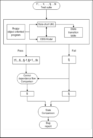
I have named my technique Object State-based Debugging for object oriented program (OSD). My technique is essentially based on first constructing models for buggy program that is state chart and ClDG. Then state transition table is created according to the state chart. Here one thing is to be noted that ClDG is incorporated with the state chart. That means each node of ClDG is accompanied with a state (state of object of same class). Then a test suite t1,...,ti,...tj,...tk, is applied as input into the buggy program. This results in some pass and some fail cases. Suppose the set of pass cases is t1,...,tj-1,tj+1,...,tk and the fail set is tj (single element). Now at this point OSD, control dependence flow comparison is made between fail set-tj and all of pass set-t1,...,tj-1,tj+1,...,tk. After the comparison, ti is the sole test input that matches the most to tj (in respect to control dependence flow). At this stage of OSD State comparison oc- curs between ti and tj, resulting bug report that points out the bug in source code level.
The important steps of my approach have been shown in figure 1; the rounded corner blocks represent initial input test suite, control dependence flow comparison, state compari- son, bug report etc. The rectangular blocks represent buggy object oriented program, ClDG, state chart UML, state transi- tion table and other output test case and sets etc. I now briefly discuss the different steps involved in my approach.
1. The Buggy object oriented program is the source code written in C++ language. It is basically a buggy code where the logic of an elevator controller (embedded system) is illustrated. My target is to debug this code.
2. The State chart UML is the finite state machine model
corresponding to the buggy program.
3. The State transition table is generated from state chart
UML model. It contains various initial and final states
with their condition and operation embedded.
4. The ClDG model represents the class dependence graph of the buggy program itself.
5. The Control dependence flow comparison block com- pares the control dependence flow between the failed and all other passed input.
6. The State comparison block compares the states of ti
and tj, between the nodes of ClDG.
7. The Bug report is the final report regarding bug
present inside the buggy program, which can point out
the location of bug in source code level.
8. The t1,...,ti,...,tj,...,tk is the input test suite.
9. The t1,..,ti,...tj-1,tj+1,...,tk is the pass input of the previous told suite.
10. The tj is the failed input from the input suite.
11. The ti is the best chosen input from the set of pass in- puts belonging to initial test suite.
Fig. 1. Overview approach to OSD.
4 DETAILED APPROACH
In this section I will describe the detailed methodology of Ob- ject State based Debugging (OSD). First thing that I will present in this portion is the buggy program.
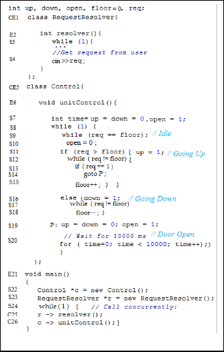
4.1 Buggy Object Oriented Program
The figure 2 is the code snippet of an elevator controller writ- ten in C++. The controller has two main parts.
Request Resolver – resolves various floor requests into sin- gle requested floor.
Control – moves elevator to its requested floor.
IJSER © 2011
http://www.ijser.org
International Journal of Scientific & Engineering Research, Volume 2, Issue 12, December-2011 3
ISSN 2229-5518
1. Description: Elevator [11] moves either up or down to reach the requested floor. Once at the requested floor, open the door for at least 10 seconds, and keep it open until the requested floor changes. It is ensured that the door is never open while moving. Elevator does not change directions unless there are no higher requests when moving up or no lower requests when moving down. In this paper, I have taken the building to be three storied (having number of floors equal to three that is - ground -0, first-1, second-2) for simplicity.
2. Prefixes introduced in program: The numbers have
been assigned sequentially to each statement in the or-
der they appear in the source code for identifying them
in the ClDG. The prefixes S, E, CE and C denote state-
ments, method entry, class entry and call nodes respec-
tively.
3. Bug intoduced: In respect to my investigation, I
have introduced a bug inside the code. Line number 13
and 14 in unitControl() method of Control class. This
results in door open when any one, requests a floor
(which is 1 in this case) from a lower floor (say floor
number 0). This repels the door to be open for 10000 milliseconds, thus not invoking the expected task
(movement). This restricts the person (standing at ground floor) to go first floor. This code works well otherwise.
4. Concurrency error ignorance: This code snippet is purely an example of concurrency. Hence the hazards regarding concurrency such as deadlock, synchroniza- tion have been ignored at time.
4.2 State Chart

I have obtained a state chart UML diagram from figure 2. The diagram is shown in the figure 3. The state chart shows four different states – Idle, Going Up, Going Down, and Door Open as the probable states. Possible transitions from one state to another is based on input (e.g., req > floor, req < floor etc.). Actions are occurred in each state (E.g., the GoingUp state u,d,o,t = 1,0,0,0 (up = 1, down, open, and timer start = 0).
4.3 State Transition Table

Table 1 refers to the state transition table generated from fig- ure 3. The transition table contains initial state, condition, op- eration or action, final state. There is another state Not De- fined– ND, that can play an important role in providing object state information to those states which can always not satisfy the given state chart criteria. Going up = u, Going Down = d, Door open = o, timer start = t are different notions of actions, that frequently occur in each state of the class (object state in- formation) under execution.
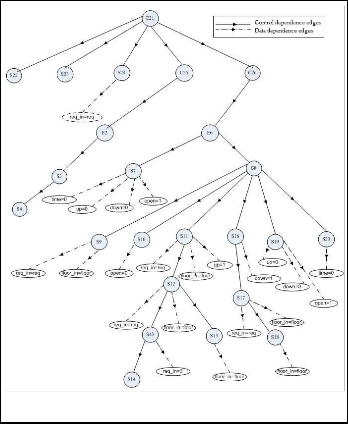
4.4 ClDG representation of the buggy program
In this section, I will generate the ClDG corresponding to the buggy object oriented program (figure 2). Along with this re- presentation, I demonstrate another ClDG incorporated with state information of class Control, from the program. I choose this class regardless of other two modules of program (e.g., class RequestResolver and void main).
1. State information incorporation to ClDG: From the program shown in figure 2, it can easily be said that the class Control is the main module that controls over the elevator movement. Hence, for simplicity I am interest- ed only to this module of the program. Here I have in- troduced a critical metric – object state information, in- to the various nodes of the ClDG of the class Control. The similar is shown in the figure 5. Where each rec- tangular box is associated with the state information to the corresponding nodes of the ClDG.
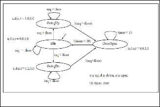
Fig. 2. Buggy Object Oriented Program snippet.
Fig. 3. State chart generated from figure 2.
IJSER © 2011
http://www.ijser.org
International Journal of Scientific & Engineering Research, Volume 2, Issue 12, December-2011 4
ISSN 2229-5518
TABLE 1
STATE TRANSITION TABLE GENERATED FROM FIGURE 3
Initial State | Condition | Operation (Action) | Final State |
Idle | req == floor | u,d,o,t =0,0,1,0 | Idle |
Idle | req > floor | u,d,o,t =1,0,0,0 | Going Up |
Idle | req < floor | u,d,o,t =0,1,0,0 | Going Down |
Going Up | req > floor | u,d,o,t =1,0,0,0 | Going Up |
Going Up | ! req > floor | u,d,o,t =0,0,1,0 | Door Open |
Door Open | timer < 10 | u,d,o,t =0,0,1,1 | Door Open |
Door Open | ! timer < 10 | u,d,o,t =0,0,1,0 | Idle |
Going Down | req < floor | u,d,o,t =0,1,0,0 | Going Down |
Going Down | ! req < floor | u,d,o,t =0,0,1,0 | Door Open |
Fig. 4. ClDG of the whole program (Obtained from figure 2).
4.5 Test suite deployment
In this portion, I will feed the buggy program with input test suite. This results in a test suite decision table. This table shows all the combination that can form from a three storied building architecture, capturing its three floors and the cor- responding requests. This table shows all the nodes belong to class Control. The ‘+’ sign represents the full execution of the respective nodes, while ‘-’ sign tells about the bypassing nodes. Finally the combinations of inputs result in the fail or pass mark, shown in figure 6.
All test cases involving <floor, req> are shown in the fig- ure 6. From this, I got the clear view of control dependence flow in respect to the nodes of ClDG. The <0, 1> input, results in failure, where as others pass. Analyzing the whole test suit decision table, it can promptly be said that input <0, 1> and
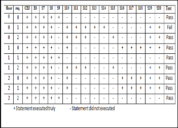
<1, 2> are closely matched to each other (in respect of control dependence flow).
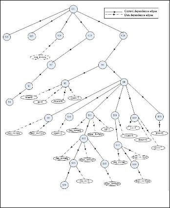
Fig. 6. Test suite decision table for class Control.
Fig. 5. State information incorporated to ClDG of the class Control.
IJSER © 2011
http://www.ijser.org
International Journal of Scientific & Engineering Research, Volume 2, Issue 12, December-2011 5
ISSN 2229-5518
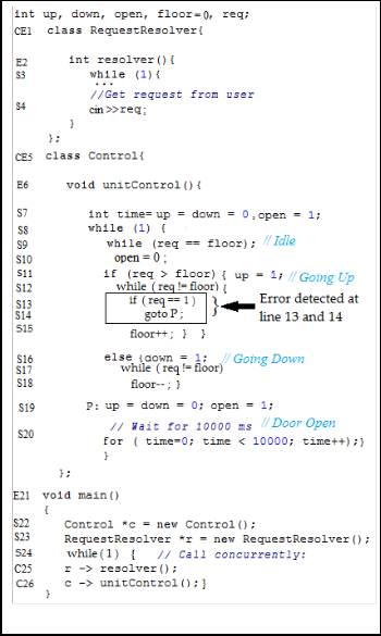
Fig. 7. State comparison between the failure and passing test cases.
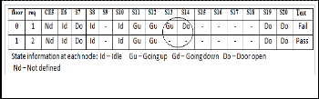
4.6 State information comparison
Here I present the state information comparison between the above pair of test inputs; the failed input <0, 1> and the pass- ing input <1, 2>. The figure 7 illustrates the whole process. Nd, Id, Do, Gu, Do represents Not defined, Idle, Door open, Going up, Going down respectively. From the figure 7, it is clear to understand that the two inputs <0, 1> and <1, 2> dif- fers at node number S13 and S14, in respect of states (Gu at S13 and Do at S14), shown in rounded form.
4.7 State comparison matrix
State comparison matrix is such a matrix that represents the state alignment of failing input to the passing one. The figure
8 shows the state comparison between <0, 1> and <1, 2>. The left most column presents the state information of passing in- put (<0, 1>). Whereas, the upper most row presents the state information of failing input (<1, 2>). The matrix basically shows a straight line starting from upper left most corner to the lower right most. The line represents the state alignment between these two test inputs. There is a slope in the line, S13 and S14 numbered columns.
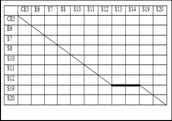
Fig. 9. Bug localization in source code level.
Fig. 8. State comparison matrix.
4.8 Source level bug detection
Now if, I take the information from the above paragraph and search the reason of the misbehavior of the line in the matrix, I can find that a couple of state changes occurred during the execution of the code. While investigating this reason, I found that line number 13 of the program involves if statement, which when executes the bug is infiltrated inside the code making it buggy. The if statement is true when it satisfies the req==1 condition, resulting the control flow to jump at line number 19. This keeps the door open, making the Door open state true. Figure 9 shows the buggy segment inside the code.
5 CONCLUSION
In this paper I have proposed a new methodology for debug- ging errors in the object oriented programs in source code lev- el. I have given an OSD model as an implementation of object state information into ClDG. I have proven the debugging methodology, incorporating a previously known buggy pro- gram into a debugged one. Currently I am busy with the im- plementation of the proposed OSD model.
REFERENCES
[1] Gregg Rothermel and Mary Jean Harrold. Selecting re- gression tests for object oriented software. In Proc. of the Intl. Conf. on Software Maintenance - 1994, pages 14-25, Victoria, BC, Canada, Sep 1994.
[2] Jeanne Ferrante, Karl J. Ottenstein, and Joe D. Warren.
The program dependence graph and its use in optimiza-
tion. ACM Transactions on Programming Languages and
Systems, 9(3):319-349, Jul 1987.
IJSER © 2011
http://www.ijser.org
International Journal of Scientific & Engineering Research, Volume 2, Issue 12, December-2011 6
ISSN 2229-5518
[3] Swarnendu Biswas, Rajib Mall, Manoranjan Satpathy and Srihari Sukumaran. A Model-Based Regression Test Selec- tion Approach for Embedded Applications. SIGSOFT Software Engineering Notes, July 2009.
[4] M. Allen and S. Horwitz. Slicing java programs that throw
and catch exceptions. In In PEPM 03: Proceedings of the
2003 ACM SIGPLAN workshop on Partial evaluation and
semantics-based program manipulation, pages 44-54,
2003.
[5] R. Gupta, M. Harrold, and M. Soa. Program slicing based regression testing techniques. Journal of Software Testing,
Verication, and Reliability, 6(2):83-112, June 1996.
[6] M. Harrold, J. Jones, T. Li, D. Liang, A. Orso, M. Pennings,
S. Sinha, S. A. Spoon, and A. Gujarathi. Regression test se-
lection for java software. In Proceedings of the 16th
ACM SIGPLAN Conference on Object Oriented Pro- gramming, Systems, Languages and Applications, pag- es 312-326, January 2001.
[7] G. Rothermel and M. Harrold. Selecting regression tegra- tion testing. In Proceedings of World Academy of Science, Engineering and Technology, volume 16, November 2006.
[8] G. Rothermel and M. Harrold. Selecting tests and identify- ing test coverage requirements for modied software. In Proceedings of the ACM International Symposium on Software Testing and Analysis, pages 169-184, August
1994.
[9] G. Rothermel and M. Harrold. A safe, efficient regression
test selection technique. ACM Transactions on Software
Engineering and Methodology, 6(2):173-210, April 1997.
[10] G. Rothermel, M. Harrold, and J. Dedhia. Regression test
selection for C++ software. Software Testing, Verification
and Reliability, 10:77-109, June 2000.
[11] Embedded Systems Design: A Unified Hard-
ware/Software Introduction, (c) 2000 Vahid/Givargis.
[12] J. Tsai, K. Fang, and Y. Bi. On real-time software testing
and debugging. In Proceedings of the Fourteenth Annual
International Computer Software and Applications Confe-
rence,, pages 512-518, 1990.
[13] S. Sinha and M. Harrold. Analysis of programs with ex-
ception-handling constructs. In In Proceedings of the In- ternational Conference on Soft- ware Maintenance, pages
348-357, 1998.
[14] S. Jiang, S. Zhou, Y. Shi, and Y. Jiang. Improving the
preciseness of dependence analysis using exception In
Proceedings of the 15th International Conference on
Computing IEEE, pages 277-282, 2006.
[15] S. Sinha and M. Harrold. Analysis and testing of pro-
grams with exception-handling constructs. IEEE Transac-
tions on Software Engineering, 26(9):849-871, 2000.
[16] R. Zhao and L. Lin. An uml statechart diagram-based
mmpath generation approach for object-oriented integra-
tion testing. In Proceedings of World Academy of Science, Engineering and Technology, volume 16, November 2006.
[17] R. Mall. Fundamentals of Software Engineering. Prentice
Hall of India, 2nd edition, 2008.
[18] Z.Li, M. Harman, and R. Hierons. Search algorithms for
regression test case prioritization. IEEE Transactions on
Software Engineering, pages 495-505, March 1996.
————————————————
Partha Pratim Ray has completed masters degree program in electronics and communication engineering in 2011 from the West Bengal University of Technology, West Bengal, India. He received bachelor’s degree in com- puter science and engineering in 2008 from the same University. He is an IEEE member. Till date, he has published 5 research papers in various journal and conference proceedings.
IJSER © 2011
http://www.ijser.org