International Journal of Scientific & Engineering Research Volume 2, Issue 4, April-2011 1
ISSN 2229-5518
Novel Object Removal in Video Using Patch
Sparsity
B. Vidhya, S. Valarmathy
Abstract— The process of repairing the damaged area or to remove the specific areas in a video is known as video inpainting. To deal with this kind of problems, not only a robust image inpainting algorithm is used, but also a technique of structure generation is used to fill-in the missing parts of a video sequence taken from a static camera. Most of the automatic techniques of video inpainting are computationally intensive and unable to repair large holes. To overcome this problem, inpainting method is extended by incorporating the sparsity of natural image patches in the spatio-temporal domain is proposed in this paper. First, the video is converted into individual image frames. Second, the edges of the object to be removed are identified by the SOBEL edge detection method. Third, the inpainting procedure is performed separately for each time frame of the images. Next, the inpainted image frames are displayed in a sequence, to appear as a inpainted video. For each image frame, the confidence of a patch located at the image structure (e.g., the corner or edge) is measured by the sparseness of its nonzero similarities to the neighboring patches to calculate the patch structure sparsity. The patch with larger structure sparsity is assigned higher priority for further inpainting. The patch to be inpainted is represented by the sparse linear combination of candidate patches. Patch propagation is performed automatically by the algorithm by inwardly propagating the image patches from the source region into the interior of the target region by means of patch by patch. Compared to other methods of inpainting, a better discrimination of texture and structure is obtained by the structure sparsity and also sharp inpainted regions are obtained by the patch sparse representation. This work can be extended to wide areas of applications, including video special effects and restoration and enhancement of damaged videos.
Index Terms— Candidate patches, edge detection, inpainting, linear sparse representation, patch sparsity, patch propagation, texture synthesis.
1 INTRODUCTION
—————————— • ——————————
ideo inpainting is the process of filling - in of the missing regions in a video. Inpainting technique is the modification of the images in an undetectable
form. Nowadays video has become an important media of communication in the world. Image inpainting is performed in the spatial domain where as video inpainting is performed in the spatio-temporal domain.
Video inpainting also plays a vital role in the field of image processing and computer vision as that of the image inpainting. There are numerous goals and applications of the video inpainting technique from the restoration of damaged videos and paintings to the removal or replacement of the selected objects in the video.
Video inpainting is used to remove objects or restore missing or tainted regions present in a video by utilizing spatial and temporal information from neighbouring scenes. The overriding objective is to generate an inpainted area that is merged seamlessly into the video so that visual coherence is maintained throughout and no distortion in the affected area is observable to the human eye when the video is played as a sequence.
Video is considered to be the display of sequence of framed images. Normally twenty five frames per second are considered as a video. Less than twenty five frames per second will not be considered as a video since the display of those will appear as a flash of still image for the human eye.
The main difference between the video and image
inpainting methods using texture synthesis is in the size and characteristics of the region to be inpainted. For texture synthesis, the region can be much larger with the main focus being the filling in of two-dimensional repeating patterns that have some associated stochasticity i.e. textures. In contrast, inpainting algorithms concentrate on the filling in of much smaller regions that are characterised by linear structures such as lines and object contours. Criminisi et al. [3] presented a single algorithm to work with both of these cases provided both textures and structures are present in images.
Nowadays, various researches are performed in the field of video inpainting due to the varied and important applications of an automatic means of video inpainting. The main applications include undesired object removal such as removing unavoidable objects like birds or aeroplane that appear during filming, to censor an obscene gesture or action that is not deemed appropriate for the target audience, but for which it would be infeasible or expensive to re-shoot the scene.
Another main application is the restoration of the videos that are damaged by scratches or dust spots or frames that may be corrupted or missing. When the video is transmitted over unreliable networks, there is a possibility of losing significant portions of video frames. To view the video again in its original form, it is necessary to repair these damaged scenes in a manner that is visually coherent to the viewer.
Initially, all the above applications were performed
IJSER © 2011 http://www.ijser.org
International Journal of Scientific & Engineering Research Volume 2, Issue 4, April-2011 2
ISSN 2229-5518
manually by the restoration professionals which were painstaking, slow and also very expensive. Therefore automatic video restoration certainly attracted both commercial organizations (such as broadcasters and film studios) and private individuals that wish to edit and maintain the quality of their video collection.
Bertalmio et al. [1], [2] designed frame-by-frame PDEs based video inpainting which laid platform for all researches in the field of video inpainting. Partial Differential Equation (PDE) based methods are mainly edge-continuing methods. In [2], the PDE is applied spatially, and the video inpainting is completed frame-by- frame. The temporal information of the video is not considered in the inpainting process.
Wexler et al [6] proposed a method for space-time completion of large damaged areas in a video sequence. Here the authors performed the inpainting problem by sampling a set of spatial-temporal patches (a set of pixels at frame t) from other frames to fill in the missing data. Global consistency is enforced for all patches surrounding the missing data so as to ensure coherence of all surrounding space time patches. This avoids artefacts such as multiple recovery of the same background object and the production of inconsistent object trajectories. This method provides decent results, however it suffers from a high computational load and requires a long video sequence of similar scenes to increase the probability of
region for every time frame of image to reproduce the original image. Last, the inpainted image frames are displayed to form the inpainted video. Here a video of short duration is considered for inpainting and the temporal domain information for each image frame is utilized to display the inpainted image frames as a video.
In this paper, Section 2 gives an overview of the image inpainting using extended examplar-based inpainting method. In Section 3, the method of video inpainting is defined. The experiments and the results are discussed in the Section 4. Finally, conclusion and the future research of the work are discussed in Section 5.
2 IMAGE INPAINTING
The most fundamental method of image inpainting is the diffusion based image inpainting method in which the unknown region is filled by diffusing the pixel values of the image from the known region. Another method of image inpainting is the examplar based image inpainting in which the region is filled by propagating the patch values of the known region to unknown region. In the previous work of this paper, an examplar based image inpainting was proposed by incorporating the sparsity of natural image patches.
0
correct matches. The results shown are of very low
resolution videos, and the inpainted static background
was different from one frame to another creating a ghost effect. Significant over-smoothing is observed as well.
Video inpainting meant for repairing damaged video was analysed in [4], [7] which involves gamut of different techniques which made the process very complicated. These works combine motion layer estimation and segmentation with warping and region filling-in. We seek
Source region 0
a0
Target region 0
a0
4Jp
4Jp’
0
a simpler more fundamental approach to the problem of video inpainting.
Inpainting for stationary background and moving foreground in videos was suggested by Patwardhan et al. [5]. To inpaint the stationary background, a relatively simple spatio-temporal priority scheme was employed where undamaged pixels were copied from frames temporally close to the damaged frame, followed by a spatial filling in step which replaces the damaged region with a best matching patch so as to maintain a consistent background throughout the sequence. Zhang et al., [7] proposed a motion layer based object removal in videos with few illustrations.
In this paper, video inpainting for static camera with a stationary background and moving foreground is considered in the spatial temporal domain. First, the video is converted into image frames. Second, the edges are found by using SOBEL edge detection method. Next, the object to be removed is inpainted using novel examplar based image inpainting using patch sparsity. The known patch values are propagated into the missing
a b
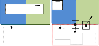
Fig.1 Patch selection

Fig.1 (a) shows that 0 is the missing region , 0 is the known region, and a0 is the fill-front of patch propagation (b) shows the two examples of the surrounding patch 4Jp and 4Jp’ which are located at edge and flat texture region respectively
The process of filling in of the missing region using the image information from the known region is called as the image inpainting. Let I be the given image with the missing region or target region 0. In the examplar based image inpainting, the boundary of the missing region is also called as the fill – front and is denoted by a0. A patch
centered at a pixel p is denoted by 4Jp.
The examplar based image inpainting is based on the
patch propagation. It is done automatically by the
algorithm by inwardly propagating the image patches
from the source region into the interior of the target
region patch by patch. Patch selection and patch
IJSER © 2011 http://www.ijser.org
International Journal of Scientific & Engineering Research Volume 2, Issue 4, April-2011 3
ISSN 2229-5518
inpainting are the two basic steps of patch propagation which is to be iterated continuously till the inpainting process is complete.
Fig.1 shows the patch selection process which is used to select the patch with highest priority for further inpainting. The sparseness of the nonzero similarities of a patch to its neighboring patches is called as the structure sparsity which is used for assigning patch priority. As shown in the Fig. 1(b), 4Jp and 4Jp’ are the patches which are centered at pixel p and p’ which lie in the edge structure and the flat texture region of the image respectively. The patch 4Jp has sparser nonzero similarities than patch 4Jp’, so it is given larger patch priority. The patch inpainting step is performed.
video inpainting is performed in both spatial and temporal domain. It is used to remove objects or restore missing regions in the video sequence. Video inpainting may also be considered as the combination of frame by frame image inpainting.
Input video
Framed Images
0 0
4Jq’’
Edges of the Target object
4Jq’
a0
4Jp
a0
0 4Jp 0
Compute the similarities of patch with its neighboring patches in the source region
Compute the patch priority
a b
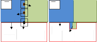
Fig.2 Patch inpainting
Fig.2 (a) shows that for the selected patch 4Jp , sparse linear combination of candidate patches { 4Jq’, 4Jq’’... 4JqN} is used to infer the missing pixels in patch 4Jp . (b) Shows the best matching patch in the candidates set has been copied into the position occupied by
4Jp , thus achieving partial filling of 0.
Fig.2 shows the procedure of patch inpainting which is used to selecte the patch on the boundary for inpainting. The selected patch on the fill-front is the sparse linear combination of the patches in the source region regularized by sparseness prior. In this paper, a single best match examplar or a certain number of examplars in the known region to infer the missing patch is not used.
The most likely candidate matches for 4Jp lie along the boundary between the two textures in the source region, e.g., 4Jq’ and 4Jp’’. The best matching patch in the candidates set has been copied into the position occupied by 4Jp, thus achieving partial filling of 0. The target region 0 has, now, shrunk and its front has assumed a different shape. Thus image inpainting is performed by the sparse linear combination of candidate patches weighted by coefficients, in which only very sparse nonzero elements exist.
3 VIDEO INPAINTING METHOD
Video is the display of the image frames in sequence. Image inpainting is done in spatial domain, whereas the
Inpaint the selected patch
Is the filling of the missing region is same as the
No
known region?
Yes
Exit
Iterate the above process for all image frames
Display all the individual inpainted image frames in order
Inpainted video as output
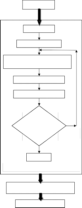
Fig. 3 Flow Diagram of the Video Inpainting
Generally all the natural images are composed of structures and textures. The primal sketches of an image
IJSER © 2011 http://www.ijser.org
International Journal of Scientific & Engineering Research Volume 2, Issue 4, April-2011 4
ISSN 2229-5518
like the edges, corners, etc are referred to as the structure of an image and the image regions with feature statistics or homogenous patterns including the flat patterns are referred to as the texture of an image.
Patch priority must be defined in such a way that it should be able to differentiate the structures and textures of an image. The structure sparsity is used for assigning priority to the patches to be inpainted. It can also be defined to measure the confidence of a patch located at structure instead of texture.
The structures are sparsely distributed in the image domain. The neighboring patches of a particular patch with larger similarities may also be distributed in the same structure or texture as the patch of interest to be inpainted. To overcome such cases, the confidence of the structure can be modelled for a patch by measuring the sparseness of its nonzero similarities to the neighboring patches.
The input to the object removal algorithm is the framed
images. Initially, the structure and texture values of the
given image are calculated and the object to be removed
is found. Edges of the object to be removed are obtained
through the edge detection and the similarities of the
patch with its neighboring patches in the source region
are computed.
Then, the patch priority is obtained by multiplying the
transformed structure sparsity term with patch
confidence term. The patch with highest priority is
selected for further inpainting. The above process is
repeated until the missing region is completely filled by the known values of the neighboring patches.
The sequence of display of the individual time frame of inpainted image is the video inpainting. Image inpainting is performed for each image frame, and all the inpainted image frames are added to form the video. Fig. 3 illustrates the overall flow diagram of the video inpainting process.
4 RESULTS AND DISCUSSION
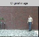
Fig 4 illustrates the important terms used in the inpainting algorithm. Fig 4. (a) shows the original image I which is given as input to the novel examplar-based image inpainting method. The natural images are generally composed of structures and textures.
A good definition of patch priority should be able to better distinguish the structures and textures, and also be robust to the orientation of the fill-front. In this paper, a novel definition of patch priority is proposed to meet these requirements. The missing region or the target region is first analysed using the algorithm as shown in the Fig 4. (b).
The structure sparsity is defined to measure the confidence of a patch located at structure instead of texture. For a certain patch, its neighboring patches with larger similarities are also distributed in the same structure or texture as the patch of interest. The patch
which has more sparsely distributed nonzero similarities is prone to be located at structure due to the high sparseness of structures. Confidence of structure for the patch and the data term of the structure are illustrated in the Fig 4. (c) and (d) respectively.
a b
c d
Fig.4 Important terms in the object removal method
Then the patch priority is computed by the product of the data term and the confidence term. The patch 4Jp with the highest patch priority on the fill-front is selected.

a b c


d e f
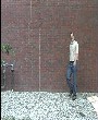
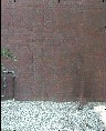
Fig.5 Steps in Video Inpainting
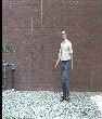
Fig. 5.(a),(b) and (c) shows randomly selected image frame of the original video sequence. Fig 5 (d), (e) and (f) shows edge detection of the image frames (a), (b) and (c) respectively.
Then inpainting is performed based on the patch
IJSER © 2011 http://www.ijser.org
International Journal of Scientific & Engineering Research Volume 2, Issue 4, April-2011 5
ISSN 2229-5518
propagation by inwardly propagating the image patches from the source region into the interior of the target region patch by patch. The above procedure is repeated for each image frames and displayed in the sequence as video.
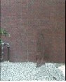
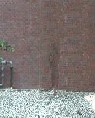
a b c
Fig. 6 Inpainted Image frames of the video sequence
Fig 6 (a), (b) and (c) illustrates the inpainted image frames for the corresponding Image Frames shown in Fig 5 (a), (b) and (c) respectively for the given video sequence.
Fig. 5 (a), (b) and (c) illustrates the randomly selected image frames in a video. Fig. 5 (d), (e) and (f) shows the edge detected image frames of Fig. 5 (a), (b) and (c) respectively. The selected patch 4Jp on the edge is inpainted by the corresponding pixels in the sparse linear combination of examplars to infer the patch in a frame work of sparse representation. The fill-front a0 and the missing region 0 are updated instantly. For each newly-apparent pixel on the fill-front, its patch similarities are computed with the neighboring patches and its patch priority.
The selected patch is used for inpainting. By iterating the above process, the filling region isinpainted successfully for the entire image frames. Fig. 6(a), (b) and (c) illustrates the inpainted image frames of the original image frames of athe video as shown in Fig. 5 (a), (b) and (c) respectively. The inpainted image frames are added together to display as a video sequence.
5 CONCLUSION
Novel patch propagation based inpainting algorithm for video inpainting is proposed in this paper. It is mainly focussed on the object removal in the image frames. Patch priority and patch representation are the two major steps involved in the proposed examplar-based inpainting algorithm for an image. Structure sparsity was represented by the sparseness of the patch similarities in the local neighborhood. The patch at the structure with larger structure sparsity is given higher priority and is used for further inpainting. The sparsest linear combination of candidate patches under the local consistency was synthesized by the patch sparse representation. Video is represented by the display of the sequence of the image frames. Hence the inpainted image
frames of each time frame is displayed as the inpainted video. Experiments showed that the proposed examplar-based patch propagation algorithm can produce sharp inpainting results consistent with the surrounding textures.
In this paper, static camera with constant background is considered. In the future, background with multiple scales and orientations, moving camera and high resolution videos will also be investigated. Video inpainting for long run (time duration) video shall be accomplished. This work can be extended to wide areas of applications, including video special effects and restoration and enhancement of damaged videos.
REFERENCES
[1] M. Bertalmio, G. Sapiro, V. Caselles, and C. Ballester, “Image inpainting,” in Proc. SIGGRAPH, 2000, pp. 417–424.
[2] M. Bertalmio, A. L. Bertozzi, and G. Sapiro, “Navier–Strokes, fluid dynamics, and image and video inpainting,” in Proc. IEEE Computer Society Conf. Computer Vision and Pattern Recognition, pp. 417–424, 2001.
[3] Criminisi, P. Perez, and K. Toyama, “Region filling and object removal by examplar-based image inpainting,” IEEE Trans. Im- age Process., vol. 13, pp. 1200–1212, 2004.
[4] J. Jia and C. K. Tang, “Image repairing: Robust image synthesis by adaptive and tensor voting,” in Proc. IEEE Computer Society Conf. Computer Vision and Pattern Recogition, pp. 643–650, 2003.
[5] K.A. Patwardhan, G. Sapiro, and M. Bertalmio, “Video inpaint- ing of occluding and occluded objects", in Proc. ICIP 2005.Vol. II, pp. 69-72.
[6] Y. Wexler, E. Shechtman, and M. Irani, “Space-time video com- pletion,” Proceedings. 2004 IEEE Computer Society Conference on Computer Vision and Pattern Recognition, vol. 1, 2004.
[7] Y. Zhang, J. Xiao, and M. Shah, “Motion layer based object removal in videos,” 2005 Workshop on Applications of Computer Vision, 2005.
IJSER © 2011 http://www.ijser.org