International Journal of Scientific & Engineering Research, Volume 4, Issue 6, June-2013 101
ISSN 2229-5518
Novel Algorithms of HVDC and FACTS in future Power Systems
ABHIJIT T. NAGHATE GAURAV G. GULHANE
abhijitnaghate@gmail.com gaurav.gulhane4@gmail.com
Abstract - A new approach to HVDC and FACTS transient/dynamic simulation based on an interactive execution of an ac transient stability program (TSP) and the Electro-Magnetic Transients Program(EMTP) is described. Through the integration of the detailed transient model of FACTS with the transient stability program, authentic simulation is achieved without simplifications. Both HVDC and Thyristor Controlled Series Capacitor (TCSC) systems are used to validate the approach, under different coupling situations between both TSP arid EMTP. From the first small DC and AC "mini networks", there are now systems transmitting 3 - 4 GW over large distances with only one bipolar DC transmission: 1.000 - 2.000 km or more are feasible with overhead lines. With submarine cables, transmission levels of up to 600 – 800 MW over distances of nearly 300 km have already been attained, and cable transmission lengths of up to 1.300 km are in the planning stage. As a multiterminal system, HVDC can also be con-nected at several points with the surrounding three-phase network. FACTS are applicable in parallel connection or in series or in a combination of both. The rating of shunt connected FACTS controllers is up to 800 Mvar, series FACTS devices are implemented on 550 and 735 kV level to increase the line transmission capacity up to several GW.
Keywords:- Facts and HVDC- Elimination of Bottlenecks - Phase Shifting Transformer- Development of Power Systems – Power Electronics - FACTS and HVDC Technology - Sys-tem Stability - Transmission Efficiency
1 Introduction
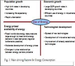
The development of Electric Power Industry follows closely the increase of the demand on electrical energy [1, 5]. Main driving factors for energy consumption are listed in Fig. 1. In the early years of power system developments this increase was extremely fast, also in industrialized countries, many decades with the doubling of energy consumption each 10 years heavily loaded due to an increasing power ex-change, the reliability and availability of the transmission will be reduced. The ac transient stability programs based on fundamental frequency, single-phase, pharos modeling techniques cannot directly represent the faster transients characterizing the HVDC and FACTS systems. Nor can they accommodate the implied waveform distortion, phase imbalance, and discrete action of semiconductor switches at different time instants. The current approach to dc system or FACTS modeling in an ac transient stability program is by a quasi steady-state model which is developed for a particular disturbance, based upon physical simulation and/or detailed transient analysis. There is a need to use ;I transient stability program (TSP) for extensive ac network modeling outside the domain of a disturb bane and at the same time to represent the parts of the network
Vulnerable for a disturbance in greater detail for transient/dynamic analysis
In large AC Systems with long distance transmission and synchronous interconnections, technical problems can be expected which are summarized in Fig. 2. Main problems occur regarding load flow, system oscillations and inter-area oscillations. If systems have a large geographic extension and have to transmit large power over long distances, additional voltage and stability problems can arise. System problems listed in Fig. 2 can be improved by use of power electronic components,
ref. to the next section.
IJSER © 2013 http://www.ijser.org
International Journal of Scientific & Engineering Research, Volume 4, Issue 6, June-2013 102
ISSN 2229-5518

be explained by the basic equation for transmission in
Fig. 4
2 Roles of HVDC and FACTS for Transco
System
In the second half of the past century, High Voltage DC Transmission (HVDC) has been introduced, offering new dimensions for long distance transmission. This development started with the transmission of power in an order of magnitude of a few hundred MW and was continuously increased to transmission ratings up to 3 -
4 GW over long distances by just one bipolar line. By
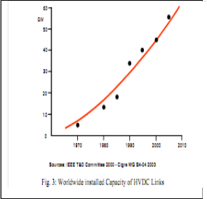
these developments, HVDC became a mature and reliable technology. Almost 50 GW HVDC transmission capacities have been installed worldwide up to now, ref. to Fig. 3. Trans-mission distances over 1,000 to 2,000 km or even more are possible with overhead lines. Transmission power of up to 600 - 800 MW over distances of about 300 km has already been realized using submarine cable, and cable transmission lengths of up to about 1,300 km are in the planning stage.
To interconnect systems operating with different frequencies, back-to-back (B2B) schemes have been applied [4]. As a multi terminal system, HVDC can also interconnect several locations in the surrounding AC network. Flexible AC Transmission Systems (FACTS), based on power electronics have been developed to improve the performance of long distance AC transmission [2, 3]. Later, the technology has been extended to the devices which can also control power flow [6]. Excellent operating experiences are available world-wide and also FACTS technology became mature and reliable. The main idea of FACTS and HVDC can
. Power transmitted between two nodes in the systems depends on voltages at both ends of the interconnection, the impedance of the line and the angle difference between both systems. Different FACTS devices can actively influence one or more of these parameters and control the power flow through the interconnection. Fig. 5 shows the principal configurations of FACTS devices. Main shunt connected FACTS application is the Static Var Compensator (SVC) with line- commutated thyristor technology. A further development is STATCOM using voltage source converters. Both devices provide fast voltage control, reactive power control and power oscillation damping features. As an option, SVC can control unbalanced system voltages. For long AC lines, series compensation is used for reducing the transmission angle, thus pro-viding stability enhancement. The simplest form of series compensation is the Fixed Series Compensation (FSC). Thyristor Controlled Series Compensation (TCSC) is used if fast control of the line impedance is required to adjust the load flow or for damping of power oscillations. The development of Electric Power Industry follows closely the increase of the demand on electrical energy [1, 5]. Main driving factors for energy consumption are listed in Fig. 1. In the early years of power system developments this increase was extremely fast, also in industrialized countries, many decades with the doubling of energy consumption each 10 years. Such fast increase is
nowadays still present in the emerging countries,
IJSER © 2013 http://www.ijser.org
International Journal of Scientific & Engineering Research, Volume 4, Issue 6, June-2013 103
ISSN 2229-5518
especially in Far-East. In the industrialized countries the increase is, however, only about 1 to 2 % per year with
an estimated doubling of the demand in 30 to 50 years.
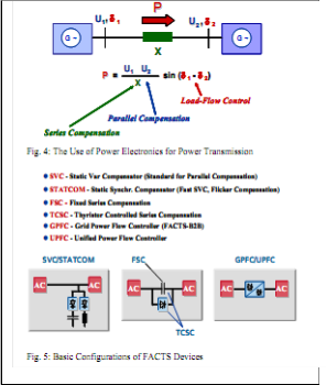
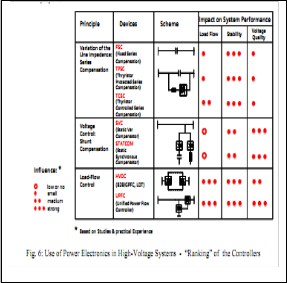
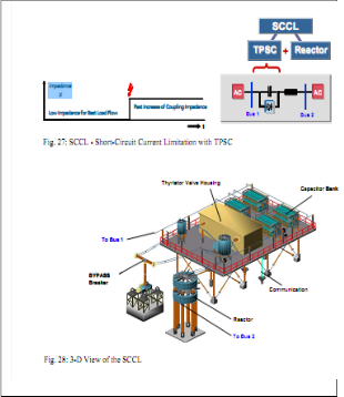
Special FACTS devices are UPFC (Unified Power Flow Controller) and GPFC (Grid Power Flow Controller). UPFC combines a shunt connected STATCOM with a series connected STATCOM, which can exchange energy via a coupling capacitor. GPFC is a DC back-to- back link, which is designed for power and fast voltage control at both terminals [8]. In this way, GPFC is a “FACTS Back-to-Back”, which is less complex than the UPFC at lower costs. For most applications in AC transmission systems and for network interconnections, SVC, FSC, TCSC and GPFC are fully sufficient to match the essential requirements of the grid. STATCOM and UPFC are tailored solutions for special needs. FACTS devices consist of power electronic components and conventional equipment which can be combined in different configurations. It is therefore relatively easy to develop new de-vices to meet extended system requirements. Such recent developments are the TPSC (Thyristor Protected Series Compensation, [1, 2]) and the Short-Circuit Current Limiter (SCCL, [8]), both innovative solutions using high power thyristor technology, ref. to section 10, “Innovations in FACTS Technology”. Fig. 6 summarizes the impact of FACTS and HVDC on load flow, stability and voltage quality when using different devices. Evaluation is based on large number of studies
and experiences from projects.
A large number of different FACTS and HVDC have been put into the operation either as commercial projects or prototypes. Static Var Compensation (SVC) is mainly used to control the system voltage. There are hundreds of these devices in operation world-wide. Since decades, it is a well developed technology and the demand on SVC is increasing further. Fixed series compensation is widely used to improve the stability in long distance transmissions. A huge number of these applications are in operation. If system conditions are more complex, Thyristor Controlled Series Compensation is used. TCSC has already been applied in different projects for load-flow control, stability improvement and to damp oscillations in interconnected systems. The market of FACTS and HVDC equipment for load-flow control is expected to develop faster in the future, as a result of the liberalization and deregulation in the power industry. The market in the HVDC field is further progressing fast. A large number of high power long distance transmission schemes using overhead lines or submarine cables, as well as back-to-back (B2B) projects have been put into operation or are in the stage of installation.
3 Comparison of Phase Shifting
Transformer with HVDC and FACTS
Phase shifting transformers have been developed for transmission system enhancement in steady state system conditions. The operation principle is voltage source injection into the line b y a series connected transformer, which is fed by a tapped shunt transformer, very similar to the UPFC, which uses VSC-Power Electronics for coupling of shunt and series transformer.[9] 100 ms is necessary with regard to voltage collapse phenomena
IJSER © 2013 http://www.ijser.org
International Journal of Scientific & Engineering Research, Volume 4, Issue 6, June-2013 104
ISSN 2229-5518
and “First Swing Stability” requirements. Such fast reaction times can easily be achieved by means of FACTS and HVDC controllers. Their response times are fully suitable for fast support of the system recovery. Hence, dynamic voltage and load-flow restoration is clearly reserved to power electronic devices like FACTS and HVDC. In conclusion, phase shifting transformers and similar devices using mechanical taps can only be applied for very limited tasks with slow requirements under steady state system conditions so, overloading of lines and loop-flows in Meshed Systems and in parallel line configurations can be eliminated. However, the speed of phase shifting transformers for changing the phase angle of the injected voltage via the taps is very slow: typically between 5 and 10 s per tap, which sums up for 1 minute or more, depending on the number of taps. For successful voltage or power-flow restoration under transient system conditions, as a thumb rule, a response time of approx...
4 Elimination of Bottlenecks in
Transmission and Interconnected Systems
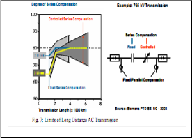
Based on the ability to control different system parameters such as voltage, impedance and angle between the system voltages, FACTS can ensure reliable operation of AC transmission up to extremely long distances. Studies showed that it is possible to transmit power over 5 to 6 thousand kilometers. Fig. 7
shows a schematic configuration of such a transmission and the degree of compensation to keep the transmission stable. For such extreme transmission systems, each of the transmission sections needs shunt compensation and controlled series compensation. The operation of such long distance transmission is, of course, possible from technical point of view. The economic aspects of such transmissions are, however, questionable. \If the AC systems are linked at different locations, power loop-
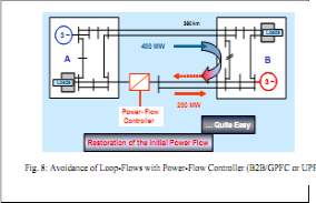
flows can occur dependent on the changing conditions
in both networks and in case of outages of lines. Fig. 8 gives an example how FACTS (in this case UPFC or GPFC as Power-Flow Controller) can direct power flow across the interconnection between two systems. In case that power should be transmitted through a meshed system, undesired load flow occur which loads other parts of the system. This can lead to bottlenecks in the system. In such cases FACTS and HVDC could help to improve the situation.
5 Examples of Large Interconnected
Systems
5.1 Europe
An example for synchronous operation of very large power systems is the UCTE system in Western Europe (Fig. 9), which has been extended step by step to the today very complex con-figuration, with the extension to Romania and Bulgaria, and later reconnection of the Balkan countries [1]. Some of the Maghreb countries in North Africa are already connected to the UCTE network and there are further plans to interconnect Turkey through Balkan countries. Furthermore, discussion is in progress on a possible interconnection to IPS/UPS system. In large power systems technical problems occur resulting from meshed systems on one hand and problems of long distance transmission on the other hand, ref. to Fig. 2. With an increasing size of the interconnected system over thousands of kilometers most of the advantages offered by the interconnection will reduce. Large blackouts in America and Europe confirm clearly, that the favorable close electrical coupling by AC might also include a strong risk of uncontrollable cascading effects in large and heavily loaded interconnected systems. Results of UCTE studies on possible interconnections between the UCTE and IPS/UPS net-works show that additional power transfer
IJSER © 2013 http://www.ijser.org
International Journal of Scientific & Engineering Research, Volume 4, Issue 6, June-2013 105
ISSN 2229-5518
through the existing system leads to bottlenecks or produces insufficient n-1 conditions at different locations in the UCTE system.
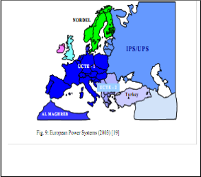
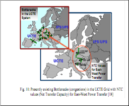
Fig. 10 shows that an additional east-west energy transfer is limited (NTC values). To avoid congestion and problems, additional investments and improvement
for the system operations will be needed ref. to section
6.
5.2 Role of HVDC and FACTS United States and
Canada
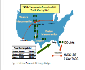
In North-America, large interconnected systems exist. In the USA and Canada there are a number of systems which are separated and which are operated asynchronously. Fig. 11 shows the situation in USA with 3 separated power systems. They are, however, interconnected by HVDC links to enable power
exchange. It must be mentioned, that the 2003 Blackout
in USA and Canada was limited to the synchronous areas only, whereas the Quebec/Canada grid, which is interconnected to the neighboring systems by a hybrid solution (AC plus DC), was not affected. Based on these experiences, further extensions of the interconnections by additional DC links are in discussion, e.g. the TAGG project in the United States, ref. to Fig. 11. The problems of large synchronous system interconnections are explained in section 6 and the benefits of HVDC are depicted in section 7.
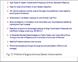
6 Problems Of synchronous Power System
Interconnections
The technical limitations of large interconnected synchronous systems have impact on the cost benefits of the interconnection. These aspects are listed in Fig. 12. High costs are needed for system adjustments and for co-ordination of joint system operation.
If the AC interconnection is weak and heavily loaded, stability problems will arise and the ad-vantages of spinning reserve sharing diminish as power has to be transmitted over long distances and can produce additional bottlenecks in the system. Therefore, enhancement of the transmission systems and control of load-flow will be essential.
IJSER © 2013 http://www.ijser.org
International Journal of Scientific & Engineering Research, Volume 4, Issue 6, June-2013 106
ISSN 2229-5518
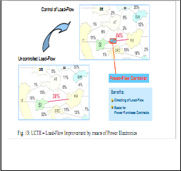
neighboring systems. Only a limited amount of power is flowing directly to the target location. Using a power electronic device for power-flow control, e.g. UPFC or GPFC, the power ex-change between the two countries
can be improved significantly.
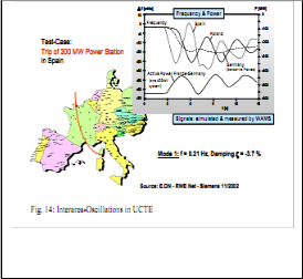
Fig. 13 shows an example of the West-European system: 500 MW should be transported from Hungary to Slovenia. It can be seen, that this power flow is spread widely through the neighboring systems. Only a limited amount of power is flowing directly to the target location. Using a power electronic device for power- flow control, e.g. UPFC or GPFC, the power ex-change between the two countries can be improved significantly.
In Fig. 14, simulation results and on-site recordings (by Wide Area Measurement System with GPS) of the European UCTE system show, that an outage of only one 300 MW generator in Spain can create large inter- area oscillations in the whole UCTE system. Magnitudes of up to 1000 MW have been experienced in the interconnection lines. Fig. 13 shows an example of the West-European system: 500 MW should be transported from Hungary to Slovenia. It can be seen, that this power flow is spread widely through the
In Fig. 14, simulation results and on-site recordings (by Wide Area Measurement System with GPS) of the European UCTE system show, that an outage of only one 300 MW generator in Spain can create large inter- area oscillations in the whole UCTE system. Magnitudes of up to 1000 MW have been experienced in the interconnection lines.
In this case, damping measures by PSS (Power System Stabilizers) at selected locations are still sufficient to avoid large system outages.
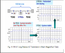
The recordings from on-site tests show that the interconnection would become unstable without the damping function of TCSC. If only one TCSC is in
operation, the interconnection becomes stable, with both
IJSER © 2013 http://www.ijser.org
International Journal of Scientific & Engineering Research, Volume 4, Issue 6, June-2013 107
ISSN 2229-5518

devices acting the inter-area oscillations are quite well damped, and redundancy is provided [3]. From site experience, it has been reported, that under increased load conditions, the TCSC damping function is activated up to several hundred times per day. In Great Britain, in the course of deregulation, new power stations where installed in the north of the country, remote from the southern load centers and some of the existing power stations in the south were shut down due to environmental constraints and for economic reasons .
7 Advantages of HVDC for Tie Line System
Stations relatively close to the load centers and the voltage levels have been chosen according to these initial conditions. However, due to the demand for interconnection to other systems and for exchange of power between them, these conditions have been changed. Power has now to be transmitted over longer distances by insufficient voltage levels and During the development of AC systems in the past, regional networks have been built up to supply energy from power systems are in general not well developed at the system borders.
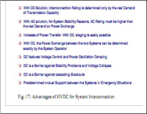
This can produce technical problems leading to bottlenecks when power has to be exchanged between the systems. The easiest way to interconnect large power systems, which are already heavily loaded, is to use HVDC. Major benefit of an HVDC link is its ability to control the power flow and its flexibility to adapt to different AC system characteristics at both sides of the interconnection. In this respect, HVDC offers significant benefits for the system interconnection. These benefits are listed in Fig. 17.
They are generally valid and do not depend on the size of the interconnected systems. The interconnection alternatives with HVDC are schematically shown in Fig.
18. The DC interconnection can be either long distance
transmission or a back-to-back link. The back-to-back solution is more suitable for exchange of moderate p owner, e.g. up to 1200 MW in the areas close to the borders of both systems. If, however, a large amount of power should be ex-changed or transmitted over long distances, the HVDC point to point transmission offers more advantages. Power can be brought directly to the spots in the systems where it is required with-out any risk to overload the AC system in between. A further advantage of such a solution is the control performance of HVDC which can effectively support the AC system stability and damp inter-area oscillations.
8 Analysis of System for Large Power
Systems
The interconnected power systems UCTE (former UCPTE plus CENTREL) and NORDEL are operated asynchronously and they are interconnected by several submarine high voltage direct current (HVDC) cable links. Because of technical and economical advantages of an increasing energy exchange between the Norwegian hydro power plants and the thermal power generation in Central Europe, new HVDC submarine cable links are planned in near future. A prerequisite for these plans is to investigate the impact of these planned HVDC links on both power systems. Therefore an international team performed extensive studies regarding steady state, transient and voltage stability of both interconnected power systems UCTE and NORDEL. Detailed system models of both power
systems adapted to the purpose of the studies have been
IJSER © 2013 http://www.ijser.org
International Journal of Scientific & Engineering Research, Volume 4, Issue 6, June-2013 108
ISSN 2229-5518
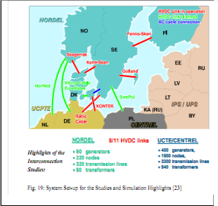
developed and tested. The existing HVDC interconnections including the new SWEPOL inter- connector as well as three new planned HVDC links between Norway, Germany and the Netherlands have been taken into account. Thus the overall system model comprises up to 11 HVDC links, see Fig. 19. For the main part of the study, the UCPTE/CENTREL system in Central Europe was modeled in the NETOMAC format. Special attention was paid to system modeling in the vicinity of landing points of the DC links. For the remaining part of the system a simplified representation was chosen. For the investigation of the system interaction of the three planned and the two existing HVDC links with the continental AC system, a detailed three-phase network model (Fig. 19) has been implemented.
Topics of the studies have been:
• System Interactions
• Dynamic Voltage Control
• Harmonic Interaction
• Voltage Stability - short and long-term
• Eigen value Analysis
• System disturbances and critical fault scenario
The investigations in time and frequency domain of the complete NORDEL and UCTE/ CENTREL system connected via 8 HVDC links showed important results
in understanding the natures of the oscillation, reveal the
sources of problems. The investigations in the time domain for evaluation of the influence of the planned HVDC-links and the corresponding transit of 1.800 MW from North to south and vice versa showed, that the planned links do not introduce stability problems for the two interconnected power systems. Due to the relatively weak connection points of the planned HVDC links in Southern-Norway, it is however advisable to spend efforts on the controller-functions of the HVDC links. In Fig. 20, results of the studies are depicted.
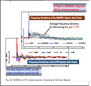
It can be clearly seen from Fig. 20, that for an AC fault in the NORDEL system, the DC inter-connection is the best and the only feasible solution for the interconnection due to a relatively large frequency deviation for more than 8 s, leading to a phase angle difference of about 115 degrees between the two systems. For an AC fault at the UCTE system side, a synchronous interconnection via an AC cable (which however would be not possible at such long distances) would be basically feasible – from the system stability point of view. As a conclusion (“lessons learned”), the
IJSER © 2013 http://www.ijser.o
International Journal of Scientific & Engineering Research, Volume 4, Issue 6, June-2013 109
ISSN 2229-5518
study experiences for the UCTE/NORDEL system interconnection demonstrate very clearly, that the extension of the systems with additional DC links is fully feasible, whereas an AC extension is questionable and would require additional measures for the frequency deviations after faults in the NORDEL system.
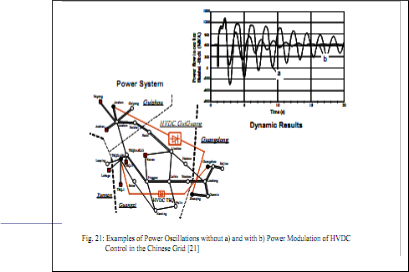
However, additional improvements (in the HVDC controllers) for power oscillation damping would enhance the system stability in any case. Such an example is shown in the following. Fig. 21 gives an example of a large power system simulation of the Chinese grid, in which HVDC has been integrated. Because of long transmission lines, the AC system experiences severe power oscillations after systems faults, close to the stability limits. In the figure, oscillations are depicted, first for the case that HVDC is just transmitting power in constant power mode (curve a). It can be seen, that strong power oscillations occur. If, how-ever, damping control of HVDC is activated (curve b), the oscillations are damped very effectively. Without HVDC, e.g. with a fully synchronous interconnection, such a large power sys-tem would be unstable in case of fault contingencies, thus leading to severe outages (Blackout).
9 Modern Generations in Power Electronic
Components
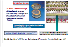
By the use of new, high power direct light-triggered thyristors (LTT), significant benefits can be achieved, as shown in the Fig. 22.
Siemens uses this innovative technology for both HVDC and FACTS controllers. Highlights are less electronic components, leading to an increased reliability, in combination with a unique wafer- integrated thyristor over-voltage protection. In Fig. 23, the stepwise assembly of the thyristors in modules and
valve group is shown. An additional, important feature
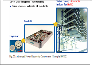
of these high power electronic components is a flame- retardant design of the elements.
10 Innovations in FACTS Technology
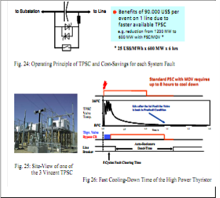
In series compensation, a capacitor is used to compensate for the lines impedance, thus the line is "virtually" shortened and the transmission angle decreased for system stability improvement. However, during transient conditions, the short-circuit currents cause high voltages across the capacitor, which must be limited to specified values. In the past, this limitation was accomplished by arresters (MOV) in combination with a spark gap. An AC-fault current flowing through a MOV always leads to a high energy dissipation of the MOV. The MOV heats up heavily. Due to an upper temperature limit the MOV must cool down before the next current stress can be absorbed. Cooling down requires a large amount of time constants of several hours are known. During this time, the series compensation must be taken out of service (bypass- breaker closed) and consequently the power transfer on the related line needs to be reduced dependent on the degree of compensation. Both the (mechanical) gap function and the MOV can now be replaced by an innovative solution with special high power light- triggered thyristors. These thyristors are designed and tested for a 110 kA peak current capability and they have a very fast cooling-down time. Using this new technology, significant cost savings after system faults can be achieved. Fig. 24 shows the principle of the TPSC and the cost savings for each fault on one of the 3 lines at the 500 kV TPSC installation at Vincent Substation, USA. In case of faults nearby the substations all 3 lines are involved in the fault strategy. Then the savings sum up to 270.000 US$ per event. Fig. 25 shows a site view of the TPSC and Fig. 26 the fast cooling-down time of the high power thyristor.
IJSER © 2013 http://www.ijser.org
International Journal of Scientific & Engineering Research, Volume 4, Issue 6, June-2013 110
ISSN 2229-5518
11 Conclusions
Increasing generation in high load density networks on one hand and interconnections among the systems on the other, increases the short-circuit power. If the short- circuit current rating of the equipment in the system is exceeded, the equipment must be upgraded or replaced, which is a very cost- and time-intensive procedure.
Short-circuit current limitation offers clear benefits in such cases. Limitation by passive elements
. As per the above study of the HVDC and FACTS we can redeveloped the concept of application of HVDC and FACTS.In addition, to avoid large cascading system outages, transmission systems and system inter- connections have to be improved by new investments, including the use of Power Electronics like HVDC, FACTS and other advanced technologies. Power systems develop on line with the increasing demand on energy. With time, large inter-connected systems came into existence. System interconnections offer technical and economical advantages. These advantages are high when medium sized systems are interconnected. However, when using synchronous AC interconnection, the advantages diminish with an increasing size of the systems to be interconnected and on the other hand, the costs to adjust the AC systems for synchronous operation increase Further developments in the future will be also influenced by the liberalization of power industry .FACTS and HVDC controllers have been developed to improve the performance of long distance AC transmission. Later their use has been extended to load-flow control in meshed and interconnected systems. Excellent on-site operating experience is being reported, and the FACTS and HVDC technology became mature and reliable. In the paper, highlights of innovative FACTS and HVDC solutions are depicted and their benefits for new applications in high voltage transmission systems and for system interconnections are demonstrated. Comparison with conventional, mechanical equipment like Phase Shifting Transformers is given.
12 References
[1] R. Kahnt, “Entwicklung der Hochspannungstechnik
– 100 Jahre Drehstromübertragung”,
[Elektrizitätswirtschaft 90 (1991), H. 11, S. 558-
576]
[2] N. G. Hingorani, “Flexible AC Transmission”, [IEEE Spectrum, pp. 40-45, April 1993]
[3] “FACTS Overview”, [IEEE and Cigré, Catalog Nr.
95 TP 108]
[4] “Economic Assessment of HVDC Links”, [CIGRE Brochure Nr.186 (Final Report of WG]
IJSER © 2013 http://www.ijser.org
International Journal of Scientific & Engineering Research, Volume 4, Issue 6, June-2013 111
ISSN 2229-5518
[5] V. Sitnikov, W. Breuer, D. Povh, D. Retzmann, E. Teltsch, “Benefits of Power Electronics
For Transmission Enhancement”, [Russia Power
Conference. March 2004, Moscow, Russia]
[6] V. Sitnikov, W. Breuer, D. Povh, D. Retzmann, M. Weinhold, “Benefits of FACTS for
Large Power Systems”, [Cigré Conference. Sept.
2003, St.-Petersburg, Russia]
[7] V. Sitnikov, D. Povh, D. Retzmann, E. Teltsch, “Solutions for large Power System
Interconnections”, [Cigré Conference. Sept. 2003, St.-Petersburg, Russia]
[8] S. Geeves, K. Bergmann, D. Retzmann, R. Witzmann, “Improvement of System Stability
By the HARKER Static Var Compensators/UK - Verification of System Performance by
Digital and Real-Time Simulation”, [ICPST 94. Oct. 1994, Beijing, China]
[9] W. Breuer, D. Povh, D. Retzmann ,” Role of
HVDC and FACTS in future Power Systems”CEPSI
2004.
IJSER © 2013 http://www.ijser.org