International Journal of Scientific & Engineering Research, Volume 5, Issue 7, July-2014 1028
ISSN 2229-5518
Nonlinear Lifting based New Wavelet Transforms for Improved Medical Image Compression
A. Hazarathaiah1, Dr. B. Prabhakara Rao2
1 HOD, Dept. of ECE, SV College of Engg., Tirupati, INDIA
a.hazarath@gmail.com
2Rector, JNTUK, Kakinada, INDIA
drbpr@rediffmail.com
Abstract— In this paper, the construction of new lifting based wavelets by a new method of calculating lifting coefficients is presented. First of all, new basis functions are utilized to facilitate new orthogonal traditional wavelets. Then by using the decomposing poly-phase matrix the lifting steps are calculated using a simplified method. The attractive feature of lifting scheme is that the construction of wavelet is derived in spatial domain only; hence the complexity in the design of traditional wavelets is avoided. Lifting scheme was used to generate second generation wavelets which are not necessarily translation and dilation of one particular function. Short and sharp basis functions are chosen so as to extract the non-uniform nature of usual image classes. Implemented wavelets are applied on a number of medical images. It was found that the compression ratio (CR) and Peak Signal to Noise Ratio (PSNR) are far ahead of that are obtained with the popular traditional wavelets as well as the successful 5/3 and 9/7 lifting based wavelets. Set Partitioning in Hierarchical Trees (SPIHT) is used to incorporate compression.
Index Terms—: Lifting Scheme, Basis Functions, compression, poly-phase representation first term, second term, third term, fourth term, fifth term, sixth term
—————————— ——————————
From the past three decades many researchers are working on wavelets and its applications. A very good review of applications of wavelets such as biomedical applications, wireless communications, computer graphics or turbulence is given in [1]. Image compression is one of the most important and visible applications of wavelets. Nowadays the digital imaging has almost replaced the print imaging, which insists large number of techniques operating on digital images. Meanwhile, the medical imaging has taken its shape from print to digital since the last decade. Hence, an attention for the design of compression techniques is required for providing lesser memory requirement with good quality in different applications. A typical image usually contains large spatial redundancy in most of the regions in image [2]. In addition to the spatial redundancy, an image contains subjective redundancy, which is determined by properties of a human visual system (HVS) [3]. An HVS permits some tolerance depending on the contents of the image and viewpoints. The redundancy (both statistical and/or subjective), thus, can be removed to achieve compression of the image data.
The basic measure for the performance of a
compression algorithm is compression ratio, defined as a
ratio between original data size and compressed data
size. In an image compression scheme, the image
compression algorithm should achieve a tradeoff between compression ratio and image quality (in the form of PSNR) [4]-[6]. Usually, if an image compression
algorithm produces high CR values, then the quality
(PSNR) will be less and vice versa. Image compression is
very important for efficient transmission and storage of
images. Demand for communication of multimedia data through the
telecommunications network and accessing the multimedia data through Internet is growing exponentially [7]. With the use of digital cameras,
requirements for storage, manipulation, and transfer of digital images, has grown explosively. These image files can be very large and can occupy a lot of memory. A gray scale image of dimension 256x256 has 65,536 elements to store, and a typical colour image of dimension 640x480 has nearly a million.
Downloading of these files from internet can be very
time consuming task. Image data comprise of a
significant portion of the multimedia data and they
occupy the major portion of the communication
bandwidth for multimedia communication. Therefore development of efficient techniques for image compression has become quite necessary [8]. The objective of image compression is to find an image representation in which pixels are less correlated. JPEG and JPEG 2000 are two important techniques used for image compression. Work on international standards for image compression started in the late 1970s with the CCITT (currently ITU-T) need to standardize binary image compression algorithms for Group 3 facsimile communications. Since then, many other committees and standards have been formed to produce de jure standards (such as JPEG), while several commercially successful initiatives have effectively become de facto
IJSER © 2014 http://www.ijser.org
International Journal of Scientific & Engineering Research, Volume 5, Issue 7, July-2014 1029
ISSN 2229-5518
standards (such as GIF). Image compression standards bring about many benefits, such as: (1) easier exchange of image files between different devices and applications; (2) reuse of existing hardware and software for a wider array of products; (3) existence of benchmarks and reference data sets for new and alternative developments.
In the field of medical, with more sophisticated
medical equipment and imaging devices, the image processing has a trademark importance. With the requirement of on-demand services, teleconferencing and video conferencing image compression is crucial for faster communication and quick decision on medical treatment. With the mention of Wavelet by Haar in his doctoral thesis in 1909, the era of wavelet has started. The decomposition of a signal in terms of non-sinusoidal function is the concept of a wavelet. Haar has utilized a Square type waveform as the basis function, and Daubechies has used a different spike like waveform as the basis function, all targeted to extract and represent information in non-stationary and signals with sharp edges and discontinuities, which was not captured by the Fourier transform. A large number of traditional wavelets are then proposed and applied on image compression.
Different lifting schemes are proposed in [9]-[13]. In
[14], four new orthogonal wavelets are devised and used
for image compression with SPIHT. In this paper the lifting version of these wavelets is derived. A simplified calculation of lifting steps is proposed and used to derive
computations as compare to traditional convolution based discrete wavelet transform. This is very attractive for real time low power applications.
• The lifting scheme allows a fully in-place
calculation of the wavelet transform. In other
words, no auxiliary memory is needed and the
original signal can be replaced with its wavelet
transform.
• Lifting scheme allows us to implement
reversible integer wavelet transforms. In
conventional scheme it involves floating point
operations, which introduces rounding errors
due to floating point arithmetic. While in case of lifting scheme perfect reconstruction is possible for loss-less compression. It is easier to store and process integer numbers compared to floating point numbers.
• Easier to understand and implement.
• It can be used for irregular sampling.
The idea of wavelet transformation is to extract
correlation structure present in real life signals to build
sparse approximation. The correlation structure is local in both frequency and spatial/time domain. Traditional wavelet transform use wavelet filters to build time frequency localisation.
Let us consider the sequence of samples of signal x(k). Z transform of this sequence can be given as,
the steps of the four new orthogonal wavelets. The rest of the paper is organised as follows. In the next section
X ( z) = ∑ x(k ) z − k
k
(1)
the lifting scheme overview was presented. In the third section, the poly-phase representation of lifting scheme is presented. In the fourth section new lifting formulation is given. The fifth section presents the simulation results and the last section concludes this
Let us consider finite impulse response (FIR) filter h
having filter coefficients h={hk1,. . . . ., hk2}. Z transform of this filter is Laurent polynomial with degree |k2-k1| given by,
k = k 2
paper.
H ( z
) = ∑
k = k1
hk z
(2)
Designing wavelets with lifting scheme includes of three steps: The first, split phase that split data into odd and even sets, second predict step, in which odd set is predicted from even set and the third update phase that will update even set using wavelet coefficient to
Filtering of signal x(k) by filter h can be easily
described in z transform by the (3)
Y(z) = H(z)X(z) (3) Sub-sampling of the signal x(k) is corresponding to keeping only the even samples i.e. xe=x(2k). Z transform
of such sub-sampled signal can be given as
calculate scaling function. Predict phase ensures
polynomial cancellation in high pass. Update stage
X e ( z)
= ∑ x(2k ) z − k k
(4)
ensures preservation of moments in low pass.
Lifting scheme of wavelet transform is being used for digital speech compression and digital image
X(z) = x(0)z0 + x(1)z1 + x(2)z2 + x(3)z3+ . . . . . . X(-z) = x(0)z0 - x(1)z1 + x(2)z2 - x(3)z3+ . . . . . .
1
compression for the following advantages over conventional wavelet transform technique.
X e ( z )
![]()
= [ X (− z) +
2
X ( z)]
= ∑ x(2k ) z −2 k
k
(5)
• It allows a faster implementation of the wavelet transform. It requires half number of
Similarly
IJSER © 2014 http://www.ijser.org
International Journal of Scientific & Engineering Research, Volume 5, Issue 7, July-2014 1030
ISSN 2229-5518
![]()
X ( z 2 ) = z [− X (− z) + X ( z)] = ∑ x(2k ) z − 2 k (6)
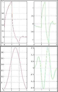
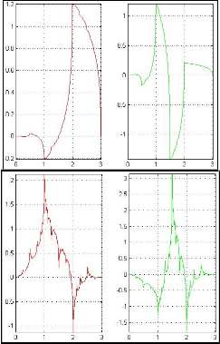
functions of the orthogonal wavelets are given in the
2 k figure 1.The wavelet filters for these wavelets are
From (5) and (6), it is clear that the signal X(z) can be decomposed into Xe (z2) and Xo (z2) as given in (7).
X(z) = Xe (z2) + z-1Xo (z2) (7) Now let us consider that signal X(z) decomposed into two parts using high pass filter g and low pass filter h,
calculated and for simplicity let
h = { h-4 , h-3, h-2 , h-1 , h0 , h1 , h2 , h3 , h4 } and g = { g-4, g-3 , g -2 , g -1 , g0 , g1 , g2 , g3 , g4 }
For the proposed wavelets h-4 =0, g-4 =0.
The poly-phase matrix before the circular convolution
then it can be represented as:
P ' z
H 'e ( z)
H 'o ( z)
lp( z)
H ( z)
( ) = G'
( z)
G' ( z)
=
X ( z)
(8)
e o
hp( z)
G( z)
h z 2 + h
+ h z −2 + h z −4
h z 3 + h
z + h z −1 + h z −3
∴ P' ( z) = −2
0 2 4
−2 −4
−3 −1
3
1 3
−1 −3
Sub-sampling step corresponds to
g −2 z
+ g 0 + g 2 z
+ g 4 z
g −3 z
+ g −1 z + g1 z
+ g 3 z


LP( z 2 ) = lp ( z 2 ) = lp( z) + lp(− z) = H ( z) X ( z) + H (− z) X (− z)
We obtain the Poly-phase matrix P(z) by applying
e 2 2
(9)
circular convolution to the elements of P’(z).Therefore
h z + h
+ h z −1 + h z −2
h z 2 + h
z + h + h z −1
P( z)
−2 0 2 4
−3 −1 1 3
HP( z 2 ) = lp ( z 2 ) = hp( z) + hp(− z) = G( z) X ( z) + G(− z) X (− z)
=
g z + g
+ g z −1 + g z −2
g z 2 + g
z + g
+ g z −1


o 2 2
(10)
−2
0 2
H e ( z)
4 −3
H o ( z)
−1 1 3
The above equations can be written in matrix form as
= G ( z)
G ( z)
LP( z 2 )
lp ( z 2 )
1 H (− z)
H ( z) X (− z)
e o
(17)
2 = ![]()
2 =
Now P(z) can be decomposed into two matrices as
HP( z )
lpo ( z )
2 G(− z)
G( z) X ( z) (11)
e ( z)
H New ( z) 1
S ( z)
In this case we first calculate all the coefficients and
P( z) =
G ( z)
G New ( z) 0 1
then throw away half of the work done. It will be more
e o
(18)
efficient if we perform sampling before filtering, mean that we compute only even part of lpand hp.
From equations (17) and (18),
H ( z) = H New
( z) + s( z)H e ( z)
lpe ( z) = [H ( z) X ( z)]e
Similarly,
= H e
( z) X e
( z) + z −1 H
( z) X o
( z)
(12)
Go ( z) = G0
New
( z) + s( z)Ge ( z)
(19)
hpe ( z) = [G( z) X ( z)]e
= Ge ( z) X e
( z) + z −1G ( z) X
( z)
(13)
One can obtain S(z) and H0New(z) by dividing H0 (z) by
He (z). S(z) will be the quotient and H0 New(z) will be the
Let us denote output of sub-sampler and low pass
filter as λ(z) and output of sub-sampler and high pass
filter as γ(z). Then above two equations can be
represented as,
remainder. Similarly H0New(z) will be the remainder in the division G0 (z) by Ge (z).S(z), H0 New(z) and G0 New(z) can calculated and given by
S ( z) = C z −1 + C z −2 + C z −3
1 2 3
λ ( z)
X e ( z)
H New ( z) = C
+ C z −1 + C z −2
γ ( z) = P( z) z −1 X
( z)
G New z = C
+ C z −1 + C z 2
0
(14)
o 4 5 6
o ( ) 7 8 9
(20)
Where, P(z) is a poly-phase matrix is given by
Where the C1 , C2 , C3 , …., C9 are constants in terms of
wavelet filter coefficients.The equation (18) becomes,
H e ( z)
H o ( z)
P( z) =
e
( z)
G ( z)
(15)
In order to achieve perfect reconstruction, filter h and g must be complementary filters that will result unity determinant of poly-phase matrix. Polyphase matrix corresponding to lazy wavelet transform will be
1 0
P( z) =
0
(16)
This poly-phase matrix will split input samples into odd and even set.
In this section the lifting steps for the new orthogonal wavelets proposed in [14] will be calculated by a simplified method of calculating lifting scheme.The basis
IJSER © 2014 http://www.ijser.org
International Journal of Scientific & Engineering Research, Volume 5, Issue 7, July-2014 1031
ISSN 2229-5518
H e ( z) = H e
New ( z) + T ( z)H
New ( z)
G ( z) = G New ( z) + T ( z)G
New ( z)
e e o
(23)
As we have calculated S(z), H0 New(z) and G0 New(z) we can calculate T(z), He New(z) and Ge New(z) by performing divisions. The T(z), He New(z) and Ge New(z) values are given by,
T ( z) = A z + A
+ A z −1
1 2 3
H New ( z) = A
+ A z −1
e 4
G New ( z) = A
5
+ A z −1
e 6 7
Now the equation (22) becomes
(24)
H ( z)
H New ( z)
A + A z −1
H New ( z) 1 0
e o
New
= 4 5
−1
o
New
−1
G ( z) G
( z)
A + A z
G ( z) A z + A + A z 1
e o
6 7
o 1 2 3
(25)
By using the equations (21), (22) and (25) the poly- phase matrix P(z) can be written in a form, so that the lifting steps both primal and dual lifting steps can be calculated.
A4
+ A z −1
H New ( z) 1 0
P( z) = −1
A6 + A7 z
New o
( z) A z + A + A z −1
(26)
1 C z −1 + C z − 2 + C z −3
1 2 3
0 1
Fig. 1 New Wavelets: phi and psi functions of NewWa1, NewWa2, NewWa3 and NewWa4
Hence the lifting scheme is devised as follows:
Split : λk x(2k)
γk x(2k+1)
Dual Lifting (Predict) : γk γk + [A1 γk-1 + A2 γk
+ A3 γk+1 ]
Primal Lifting (Update) : λk λk + [C1 λk+1 + C2 λk+2 +
C3 λk+3 ]
Inverse Primal Lifting (Update) : λk λk - [C1 λk+1 +
C2 λk+2 + C3 λk+3 ]
Inverse Dual Lifting (Predict) : γk γk + [A1 γk-1 +
A2 γk + A3 γk+1 ]
Merge :x(2k) λk x(2k+1) γk
In this section the simulation results which includes the lifting steps as well as the performance of new lifting and traditional wavelets on medical image compression is presented. Four new orthogonal wavelets proposed in [14] are considered. The lifting steps and wavelet filters for the first wavelet is presented here.The wavelet filters
H ( z)
C + C z −1 + C z −2 1
C z −1 + C z −2 + C z −3
P( z) = e
4 5 6
−1
−2
for the first wavelet is given by
Ge ( z)
C7 + C8 z
+ C9 z
0
1 (21)
h = { 0 -0.1167 0.1274 0.1838 -0.2556 -0.2760
Now the first matrix in the above equation can further be decomposed into two matrices as,
0.4341 0.4443 -0.6396}
g = { 0 -0.6396 -0.4443 0.4341 0.2760 -0.2556 -
e ( z)
H New ( z)
H New e ( z)
H New ( z) 1 0
0.1838 0.1274 0.1167}
New
=
New
New
Ge ( z) Go
( z)
Ge
( z) Go
( z) T ( z)
1 (22)
The constants C1, C2, . . . , C9 for the first wavelet are
given as follows.
From equation (22),
C1 = -0.9155, C2 = 8.6276, C3 = 25.9327, C4 = 2.7420, C5 = -5.7385, C6 = 16.5853,
IJSER © 2014 http://www.ijser.org
International Journal of Scientific & Engineering Research, Volume 5, Issue 7, July-2014 1032
ISSN 2229-5518
C7 = -5.3383, C8 = 3.7607, C9 = -3.0254.
The constants A1 , A2 , . . . , A7 are given as follows.
A1 = 0.0465, A2 = 0.0040, A3 = -0.1143,
A4 = -1.3627, A5 = 1.8961, A6 = 0.5588, A7 = -0.3459.
The fundamental difficulty in testing an image compression system is how to decide which test images to use for the evaluations. The image content being
viewed influences the perception of quality irrespective of technical parameters of the system [15]-[18]. Normally, a series of pictures, which are average in terms of how difficult they are for system being evaluated, has been selected. To obtain a balance of critical and moderately critical material we used a wide variety of medical images.
TABLE I. CR and PSNR values with previous techniques
10bpp. The PSNR with the existing traditional wavelets is just around 23dB except for Coiflet wavelet, for which the PSNR is 40dB. PSNR with new traditional wavelets is around 30dB and with 5/3 and 9/7 lifting based wavelets it is over 37dB. In total the compression performance of new traditional wavelets is a better in terms of PSNR to that of existing traditional wavelets and the 5/3 and 9/7 lifting based wavelets completely outperform both the traditional schemes in terms of both CR and PSNR.
The proposed lifting version of the new traditional
wavelets has produced even better compression results.
In the figures 2 and 3, the GUI used in MATLAB and the
sample medical images are shown. CT and MRI images
of Brain, Heart and Head are taken as the sample images. The PSNR and CR obtained with the proposed lifting scheme are given in the tables II and III, respectively.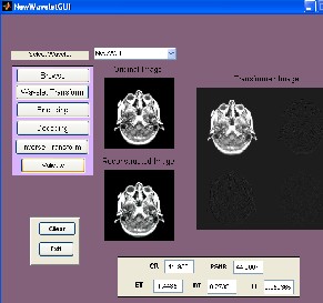
Fig. 2 Sample Screen shot of GUI
The PSNR with the lifting version of new wavelets is ranging from 40 to 44dB. The CR with the lifting version of new wavelets is about 12bpp. The comparison of performance of various transforms is plotted in figures 4 and 5. In these figures the PSNR and CRs obtained with
‘mri1.jpg’ image are plotted.
First of all the compression performance of existing
traditional wavelets, new traditional wavelets and
popular 5/3 and 9/7 lifting based wavelets is presented
for ‘mri1.jpg’. The CR and PSNR with the above
mentioned techniques are presented in the table.The CR with the existing traditional wavelets as well as proposed traditional wavelets is about 3bpp. But with the 5/3 and 9/7 lifting based wavelets the CR is about
IJSER © 2014 http://www.ijser.org
International Journal of Scientific & Engineering Research, Volume 5, Issue 7, July-2014 1033
ISSN 2229-5518
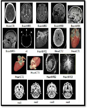
Fig. 3 Sample Images considered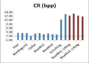
TABLE II.CR values obtained with New Lifting based
Wavelets
TABLE III. PSNR values obtained with New Lifting based Wavelets
Fig. 4 Comparison of CR values obtained with various transforms
IJSER © 2014 http://www.ijser.org
International Journal of Scientific & Engineering Research, Volume 5, Issue 7, July-2014 1034
ISSN 2229-5518
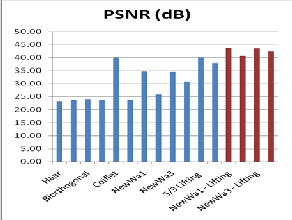
Fig. 5 Comparison of PSNR values obtained with various transforms
In this paper a new lifting mechanism was proposed. First, a new set of basis functions are selected and utilized to realize new traditional wavelets. The wavelet filters h and g are then calculated. From these filters, the poly-phase matrix p(z), by which after decomposing it into three sub-matrices, lifting steps can be calculated is formed. First this matrix is divided into multiplication of two sub-matrices which gives primal lifting. Then the first sub-matrix is again divided into multiplication of two more sub-matrices, whereby deriving the dual lifting. The wavelets after applying the proposed lifting scheme are applied on medical image compression. The CR, PSNR, Decoding time, Encoding time and transforming times are calculated. Except CR and PSNR the remaining design metrics are more or less the same with that of existing traditional, new traditional and the popular 5/3 and 9/7 lifting based wavelets. The CR with existing and new traditional wavelets is around 3bpp, with 5/3 and 9/7 lifting based wavelets it is 10 to 12bpp, and with the new lifting wavelets it is around 12bpp. The PSNR with existing traditional wavelets is less than
25dB except with coiflet wavelet for which the PSNR is
around 40dB. With the new traditional wavelets the
PSNR is around 35dB, with 5/3 and 9/7 lifting based
wavelets the PSNR is ranging from 35 to 40dB. With the new lifting wavelets the PSNR is between 40 and 45dB. Hence one can say that the new lifting based wavelets are comparatively best among the mentioned wavelets.It is expected that with modified SPIHT better results will be obtained.
[1] Proc. IEEE (Special Issue on Wavelets), vol. 84, Apr. 1996.
[2] N. Jayant and P. Noll, “Digital Coding of Waveforms: Principles and Applications to Speech and Video”, Englewood Cliffs, NJ: Prentice-Hall, 1984.
[3] N. Jayant, J. Johnston, and R. Safranek, “Signal compression based on models of human perception,” Proc. IEEE, vol. 81, pp. 1385–
1422, Oct. 1993.
[4] B. Zovko-Cihlar, S. Grgic, D. Modric, “Coding techniques in multimedia communications,” in Proc. 2nd Int. Workshop Image and Signal Processing, IWISP’95, Budapest, Hungary, 1995, pp.
24–32.
[5] Vinay U. Kale, Shirish M. Deshmukh, “Visually Improved Image Compression by Combining EZW Encoding with Texture Modeling using Huffman Encoder”, IJCSI International Journal of Computer Science Issues, Vol. 7, Issue 3, No 11, May 2010.
[6] W. Woo and A. Ortega, “Stereo image compression based on disparity field segmentation,” SPIE Conference on Visual Communications and Image Processing, vol. 3024, pp. 391-402, San Jose, California, February 1997.
[7] http://www.3.interscience.wiley.com
[8] Greg Ames,"Image Compression", Dec 07, 2002.
[9] Roger L. Claypoole, Jr., Geoffrey M. Davis, WimSweldens, Richard G. Baraniuk, “Nonlinear Wavelet Transforms for Image Coding via Lifting”, IEEE Transactions On Image Processing, Vol. 12, No.
12, December 2003.
[10] M. Kaaniche, A. Benazza-Benyahia, B. Pesquet-Popescu, J.- C.
Pesquet, “Vector Lifting Schemes for Stereo Image Coding”, IEEE Transactions on Image Processing 8, 11 (2009) 2463-2475.
[11] R.Ramanathan,K.Kalaiarasi,D.Prabha, “Improved wavelet based compression with adaptive lifting scheme using Artificial Bee Colony algorithm”, International Journal of Advanced Research in Computer Engineering & Technology (IJARCET) Volume 2, Issue 4, April 2013.
[12] Karthikeyan A, Saranya P, Jayashree N, “An Efficient VLSI Architecture for 3D DWT Using Lifting Scheme”, International Journal of Engineering Science and Innovative Technology (IJESIT) Volume 2, Issue 1, January 2013.
[13] M. Kaaniche, B. Pesquet-Popescu, J.- C. Pesquetand A. Benazza- Benyahia, “Adaptive Lifting Schemes With a Global ℓ1
Minimization Technique For Image Coding”, IEEE International
Conference on Image Processing, United States (2012).
[14] A. Hazarathaiah, Dr. B. PrabhakarRao, “A Novel Medical Image Compression using New Traditional Orthogonal Wavelets”, CiiT International Journal of Digital Image Processing, December
2013.
[15] M. Kaaniche, A. Benazza-Benyahia, B. Pesquet-Popescu, J.- C.
Pesquet, “Non Separable Lifting Scheme with Adaptive Update Step for Still and Stereo Image Coding”, Signal Processing 91, 12 (2011) 2767-2782.
[16] Chengjiang Lin, Bo Zhang, and Yuan F. Zheng, “Packed Integer Wavelet Transform Constructed by Lifting Scheme”, IEEE Transactions On Circuits And Systems For Video Technology, Vol. 10, No. 8, December 2000.
[17]SiweiLyuEero P.Simoncelli,“Nonlinear Image RepresentationUsing Divisive Normalization”, IEEE Conference on Computer Vision and Pattern Recognition,Anchorage, Alaska, June 24-26, 2008.
[18] S. Bauer, B. Zovko-Cihlar, and M. Grgic, “The influence of
impairments from digital compression of video signal on perceived picture quality,” in Proc. 3rd Int. Workshop Image and Signal Processing, IWISP’96, Manchester, U.K., 1996, pp. 245–248.
IJSER © 2014 http://www.ijser.org
International Journal of Scientific & Engineering Research, Volume 5, Issue 7, July-2014 1035
ISSN 2229-5518
.
.
IJSER © 2014 http://www.ijser.org