Inte rnatio nal Jo urnal o f Sc ie ntific & Eng inee ring Re se arc h Vo lume 3, issue 1, January -2012 1
ISSN 2229-5518
New features for performance enhancement of experimental Model Bubbling Fluidized Bed
Combustor
Raji T. O, Oyewol a O.M, Salau T.A.O.
Abs tract— Fuel f lexibility and capacity to burn broad spectrum of f uels at high combustion eff iciency w ith minimum e miss ions of greenhouse gases are f ew of the key advantages f luidized bed combustion technology has over other existing combustion technol ogy. This report examines the design, development and testing of an experimental mode l Bubbling f luidized bed combustor. Th ree unique f eatures to enhance perf ormance of this system w ere suggested and comprehensively discussed; inert bed’s temperature regulating unit, an
integrated unit that enable Fluidizing air pre-heating as w ell as Biomass f eeding pipe’s cooling and segmentations of the Combustor body into modules /partitioning of these modules into low er and upper section. The results of the test run w ith Palm kernel shell and Coconut shell show that the system performance is enhanced and that the temperature is w ell regulated as observed in the thermal distribution. It
is theref ore proposed that the present Bubbling Fluidized bed combustor could be benef icial to development of commercial size s f or pow er generation in Nigeria and Africa sub region.
Inde x Terms:- Bubbling, Fluid ized Bed, Biomass, combustion, design analysis, Experimental model, enhancement, Perf ormance, Renew able energy,
—————————— ——————————
1. I NT RO DUC T I ON
Bubbling fluidized bed combustor (BFBC) have different components functioning in unison to burn wide variety of fuels in an efficient and environmentally friendly manner. It employed strong stream of fluidizing air with approach velocity Vo such that Vo is greater than the minimum fluidizing velocity Umf and less than the full fluidization velocity Uff ; Umf≤Vo ≤Uff .; at this stage the fluidization regime is characterized by bubbles formation and vigorous mass turbulence, the bed particles exhibits property of fluid and assumes appearance of a boiling liquid; the bed at this point is said to be in Bubblin g Fluidized Stage. This fluidization characteristics and the selected feed rate are essentially the basic criteria that determined the dimension of any BFBC and capacity of its auxiliary equipment e.g. Blower, the Biomass feeder, cyclone separator etc. When Vo<Umf (minimum fluidizing velocity) the bed material remain a fixed bed (packed bed), at the other extreme when Vo≥Ut (terminal velocity) the bed mobilizes and transition to Circulating Fluidized Bed (CFBC) occurred see fig 1.

Raji, T,O is currently pursuing PhD degree program in the Department of Mechanical engineering, University of Ibadan, Ibadan. Nigeria. Em ail: rhadtrust2@gmail.com
Oyewola O.M is a Reader and the current Acting Head; Department of mechanical engineering, University of Ibadan, Ibadan. Nigeria. Email: ooyewola@yahoo.com
SalauT.A.O is a senior lecturer in the same Department. Email:
tao.salau@mail.ui.edu.ng
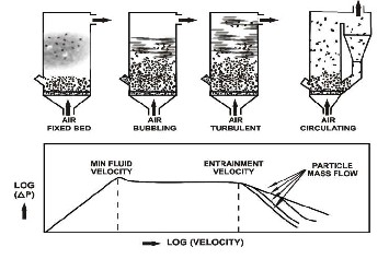

Fixed, Bubbling & Fast Fluidized Beds: As the velocity of a gas flowing through a bed of particles increases, a value is reached when the bed fluidizes and bubbles form as in a boiling liquid. At higher velocities the bubbles disappear; and the solids are rapidly blown out of the bed and must be recycled to maintain a stable system.
Fig.1 A schematic drawing shows transition from packed bed to circulating bed.[15].
Fluidized Bed Combustion technology (FBC) has been shown to be a versatile technology capable of burning practically any waste combinations with low emissions ([1],[4]) it has gone beyond being a mere idea to a proven technology for efficient combustion of difficult to burn wastes and biomass .
IJSER © 2012 http :// www.ijser.org
Inte rnatio nal Jo urnal o f Sc ie ntific & Eng inee ring Re se arc h Vo lume 3, issue 1, January -2012 2
ISSN 2229-5518
Flue gas analyzer
Gas cyclone
utilized, only an insignificant portion of it is used for cooking or domestic processing vast majority of it is left unused in the farm creating environmental nuisance, since it could not rot and is useless for agricultural cultivation. It is worthy of note that even the use of EFB and PPF as local broom and domestic cooking fuel is fast reducing with modernization, as plastic brooms and modern way of cooking is now taking predominant share. Considering about 2.5million hectares of palm trees cultivated yearly [17 ], a huge quantity of PKS and other palm waste components which could otherwise be used for energy generation is wasted, a huge loss considering the
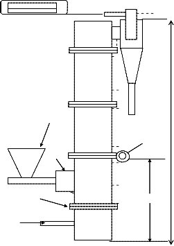
Biomass feeder Upper section 2900
hinges
G
Distributor plate lower section air in via G

Ф150

nine thermocouples (T1 – T9) arranged axially along the combustor body.
G Fluidizing air pre-heater/Biomass feeding
pipe’s cooling attachment.
Lower section is module 1& 2
Upper section is module 3, 4& 5
Fig 3: Schematic drawing of the developed BFBC.
Biomass resources like woods, grasses, plant and animal wastes are the leading sources of energy generation in Nigeria contributing about 37% of energy demand. With annual turnover of 144million tonnes/year [3] it is particularly popular among the rural dwellers and small section of urban populace who generally employ method of open air burning of the biomass, which limit the thermal efficiency of the combustion to the lowest possible. Apart from firewood which is used for domestic cooking other agricultural and silvicutural wastes like Coconut shell, Oil palm solid wastes, cassava sticks, maize stems etc, are generally left wasted in the farm. One of the key agricultural crops in Nigeria is palm tree. It is found predominantly in southern Nigeria especially in the wet rain forests and savannah belt. It also exists in the wet parts of North central Nigeria, in areas like Southern Kaduna, Kogi, Kwara, Benue, Niger, Plateau, Taraba and Nasarawa States as well as the Federal Capital Territory (FCT) [17]. Solid waste from palm tree comprises of empty fruit branches (EFB), palm press fibres (PPF) and palm kernel shell (PKS) this waste collectively account for 48% of the original palm fruit branches, PKS alone account for 8% [4]. In Nigeria virtually every part of this wonder tree is traditionally useful for one thing or the other, however PKS is not been maximally
aggregate energy generation possible if such biomass could be fired with appropriate technology.
The potential of agricultural waste as fuel for energy generation has been investigated by many researchers. Srinivasa Rao et al [1] investigated the effect of secondary air injection on combustion efficiency of sawdust in a BFBC with an enlarged disengagement section, maximum combustion efficiency of 99.2% efficiency was observed at 65% excess air. Suthum P [4] examined the characteristics of palm waste when combusted in BFBC with modularly constructed combustion body of diameter 150mm. The study showed that oil palm waste could be burnt successfully in a BFBC, it was discovered that the relationship between excess air and combustion efficiency is such that CE increases with EA; reach a maximum value for a particular feed rate, then starts to fall: this was explained with the fact that beyond the maximum point the EA promotes higher elutriation of unburnt fuels particle. A maximum CE of 92.47 was achieved at 50% excess air. Rosyida P et al[2] reported that the use of air staging is beneficial to reduction of CO emission when palm waste is combusted in a BFBC, a maximum combustion efficiency of 89% was achieved for palm fiber. Achieving high CE when biomass is used as fuel is not always the norm for instance an investigation conducted by [16] achieved less than 32% thermal efficiency in several experiments using inclined grate burner to combust PKS.
The foregoing results confirmed that Biomass could be combusted at higher efficiency and with lower emission of NOx and CO in BFBC than in conventional combustion technology such as grate burner.
Furthermore it could be seen from the above examples that each literature employed BFBC with different modification for instance from the suggestion that increased residence time promote volatile combustion, [1] employed a BFBC with an enlarged freeboard section to achieve more than 99% CE of sawdust. Clearly it could be seen from all the examples cited, that modifications to BFBC were employed to optimize its performance; a confirmation that further modifications and features may be imperative to making FBC a more efficient and more environmentally friendly method for combusting fuels.
Three performance enhancing features targeted at addressing potential problems of BFBC were examined in this work.
IJSER © 2012 http :// www.ijser.org
Inte rnatio nal Jo urnal o f Sc ie ntific & Eng inee ring Re se arc h Vo lume 3, issue 1, January -2012 3
ISSN 2229-5518
2. PERFORM ANCE ENHANCI NG F EATURES
The features discussed here are added as alternative solution
to key issues normally associated with BFBC especially when Biomass is used as fuel. Features suggested and examined in this work include the following:
i. Inert Bed Temperature Regulating Unit (ITRU); In BFBC, temperature is generally and deliberately kept below 950 oC, the bed temperature being always lower (often 650-800oC); this is to limit formation of atmospheric NOx and to prevent ash fusion a condition that is detrimental to fluidization of inert particles. Conventional approach employed water cooled coil to limit the bed temperature to acceptable level, water cooled coil immersed in bed apart from being costly, impose additional technical complication and could potentially affect fluidization characteristic of inert bed; in the present work an electronic feedback system was employed, it senses the temperature of the inert bed and via an electro-mechanical mechanism, controls the biomass feeder and fluidizing air supply as necessary. The ITRU comprises of Temperature controller, a type-K thermocouple, and two 40Amps contactors. The circuit is constructed in such a way that the biomass feeder motor is de-activated and activated as necessary to ensure the inert bed temperature is maintained at the preset temperature. See fig 6b.
ii. Fluidizing air pre-heater / Biomass feeding pipe’s cooling attachment: this feature is incorporated for two purposes; firstly to prevent the biomass from burning before entering the fluidized bed and secondly to utilize the heat energy that would otherwise be wasted and consequently cut down the fuel usage per useful energy generated. This unit is shown as G in fig 3.
iii. Modular construction / partitioning of the combustor body: Modular construction of BFBC body is not a new idea [4], one obvious purpose is to enable ease of installation of the equipment. In addition to this, modular construction could enable ease of varying the height of experimental model (when necessary) by removing or including one or more modules, for experimental purposes varying the height might be necessary to understand the effect of freeboard height on combustion characteristics of fuel being studied. In this work function of modules was further optimized via partitioning of the combustor body into lower and upper section; module 1
& 2 fixed together form lower section and the remainder when fully assembled is the upper section. The objective here is to enable observation of the fluidization process, and even the combustion process at elevated temperature for instance picture shown as fig.9 is only possible because of this new feature, also with the partitioning real time measurement of biomass feeder discharge via collection of the biomass at the discharge point is now possible.
3. BASIS FOR DESIGN OF T HE BF BC
The following were used as the basis for estimating the size of
BFBC.
A) Experimental model implies immense size is not critical, hence to ensure minimal spending smaller size BFBC and low feed rate were considered. Feed rate fd is selected as 4kg/hr –
6kg/hr for economy reason.
B) Diameter Ф was chosen as 150mm, because the selected feed rate requires appropriately small cross sectional diameter, furthermore this fd and Ф lies within a range that is popular and known to have been used successfully in literature [2],[3],[4].
C)Height (H): fuels are made up of fixed carbon, moisture, ash and Volatile matter; because of the ways volatile burnt, height of BFBC needs to be significant. Volatile are normally released at the bed and a major proportion of it burns in the freeboard, it therefore follows that to efficiently burn fuel such as Biomass (high volatile matter content) a greater height will be needed for higher value of feed rate (fd). Suthum P[4] used BFBC with 150mm diameter, height=2.3m and fd, < 2.2kg/hr, therefore the developed BFBC which is designed for a higher feed rate should logically have height equal or greater than [4]. H was chosen as 2900mm in the current work.
D)A necessary requirements for BFBC is that the bed must be secured in bubbling fluidized mode therefore at the selected feed rate the velocity Vo of the fluidizing/combustion air
must satisfy the condition; Umf≤Vo ≤Uff .
E)Typical temperature within BFBC is 800 oC to 950oC; BFBC must operate at sufficiently low temperature to inhibit formation of NOx and to prevent Ash fusion in the inert bed. In the developed BFBC an electronic control unit was incorporated to regulate/limit the inert bed temperature to desirable value. This is a neater, more precise and less cumbersome method than the water-cooled metal tube that is often used.
4. DESIGN ANAL YSIS
With fd,, Ф and H established, the dimension of auxiliary
components listed below were evaluated.
Centrifugal blower
Distributor plates
Standpipes/bubble caps specifications and Numbers
Biomass Feeding Unit
Cyclone Separator.
5. CENT RIFUGAL BLOW ER
Palm kernel shell (PKS) and Coconut shell(CS) are used as
sample fuels for the present design. Typical proximate and ultimate analysis of PKS an d CS, from literature [4]and [5], are shown below
Table1: Proximate analysi s (% b y mass on dr y ba si s, )

Items PKS[4[ CS[5]
IJSER © 2012 http :// www.ijser.org
Inte rnatio nal Jo urnal o f Sc ie ntific & Eng inee ring Re se arc h Vo lume 3, issue 1, January -2012 4
ISSN 2229-5518
Blower Airmax =34.988kg/hr.
Table2: Ultimate Analysi s (% by ma ss on d ry ba si s)
Elements | PKS | CS |
Carbon | 45.61 | 46.22 |
Hydrogen | 6.23 | 5.2 |
Oxygen | 37.51 | 41.63 |
Nitrogen | 1.73 | 0.26 |
Sulphur | NIL | NIL |
Ash | 1.01 | 3.00 |
NCV KJ/kg | 18000 | 17408 |
Minimum and maximum air requi rement for combu stion (u sing PKS )
Relevant combustion equations may be written as;
2H2 + O2 = 2H2O C + O2 = CO2
N2 + O2 = 2NO
Using the above, O2 requirement is calculated as in table 3
Table 3: Oxygen requirement for combu stion o f 1kg o f
PKS
Elements | kg/kg of fuel | O2 needed |
Carbon | 0.4561 | 1.216 |
Hydrogen | 0.0623 | 0.4984 |
Oxygen | 0.3751 | 0 |
Nitrogen | 0.0173 | 0.0198 |
Sulphur | 0 | 0 |
Ash | 0.0101 | 0 |
A key objective of fluidized bed combustion of fuel is to inhibit formation of NOx a major Greenhouse gas(GHG), this is achieved via limiting the combustion temperature to a level below threshold of thermal NOx formation (around 1400 oC). In BFBC temperature is generally below 950 OC hence oxygen required for combustion of atmospheric nitrogen may be justifiably excluded.
Therefore oxygen requirement (kg) = 1.7342
oxygen needed from the fluidizing air=1.7342-
0.3751=1.3591kg,
Since oxygen account for approximately 23.3% of air, then air requirement for complete combustion of 1kg of PKS is 5.833kg.
Using fd, minimum and maximum air requirement is calculated as below;
Blower Airmin = 23.32kg/hr
These are the minimum and maximum theoretical air requirement, while the minimum is in order, the value obtained for maximum must be increased sinc e it is a known fact that stoichiometric air is never sufficient for complete combustion, furthermore to enable comprehensive emission and combustion analysis of any given fuel it is appropriate to investigate the effect of up to 100% excess air (100% EA); this implies that our target maximum air requirement should actually be close to 80kg/hr (2x35kg/hr).
A single output Centrifugal Blower (powered by 2850rpm, 3hp,
3phase electric motor and rated maximum output 0.6944m3/s at
40oC) equipped with 2 inches Gate valve for regulating the air flow- rate from 0 to maximum was employed.
6. DISTRI BUT OR PL AT E
The Distributor plate, act as a support and passage via which
fluidizing / combustion air enters the inert particles to ensure their constant agitation and to prevent formation of zone of de-fluidization. The distributor plate is made from stainless steel with numbers of bubble-caps arranged in a definite geometric pattern. Each bubble-cap bears numbers (Nor) of orifice of appropriate diameter (do) via which the fluidizing air enters the inert bed.
Distributor plate with bubble caps though complicated and more expensive to fabricate has several advantages over other designs, such as
i. It prevent sand from leaking through the fluidizing orifices and more uniform fluidization is possible.
ii. The undisturbed layers of sand below the orifices act as heat
shield, hence insulation for the distributor plate.
7. Nor AND d o ARE ESTIM AT ED AS FOLLOWS
The total pressure drop in a fluidized bed is summation of
three components
W g
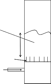
hb =300mm bubble caps
Air in
IJSER © 2012 http :// www.ijser.org
Inte rnatio nal Jo urnal o f Sc ie ntific & Eng inee ring Re se arc h Vo lume 3, issue 1, January -2012 5
ISSN 2229-5518
At Vo
Fig3: schematic drawing of the distributor plate showing the effective height of the bed as hb
ΔP= ΔPs+ΔPw+ΔPf
ΔPs= pressure drop due to weight of the packed bed.
ΔPw= pressure drop from friction at the wall, is comparatively smaller than ΔPS because of the large wall surface and the fluidizing air further reduces the friction at the wall
ΔPf= Pressure drop due to weight of fluid in bed. As a result of vast difference in density, pressure drop due to the fluid is negligible when compared to the packed bed of sand.
From the above and Bernoulli equation, total pressure drop may be written as
ΔP= ΔPs = (1-εmf)hb ρg (1)
Where, εmf = is void fraction, typical value for sharp sand is 0.4 [6].
Pressure drop across the distributor plate [1],[18]
ΔPd = 1/10 x ΔP (2)
Uor exit velocity through the orifice (radial holes) could be evaluated as
1

2P 2
a)fluidizing air enters the inert bed at 473K,
b) bed temperature during combustion is 1023K,
c) ρ =1600kg/m3 [13],
Nor is calculated as 300holes, with do = 1.5mm.
8. BIOMASS F EEDER
Biomass feeding unit essentially comprises of the Feed hopper, screw conveyor, and the low speed / high torque motor.
8.1 Screw conveyor
For a screw conveyor according to [8] Quantity of material
transported per hour Q (equivalent to fd) may be written as
Q = 15.β.π.D2.P.NﻻK (6)
To achieve the proposed feed rate a small screw is definitely needed, hence a screw of diameter Dr = 5cm and pitch (p)=2.5cm was considered. The challenge then remains calculating the appropriate RPM.
From the literature ([8],[9]) the following assumptions were made.
β=0.4, since the material to be transported (PKS and CS) are
light and non abrasive. (7)
k=1, since our conveyor is horizontal, the angle of inclination is 00 (8)
7 and 8 in equation 6 yields
Q = fd = 1.061N (9) Substituting fd the desired speed range is obtained as
U d C
or d
(3)
Nmin = 3.77 RPM
Using Wen and Yu (1966) correlation [6]
Nmax = 5.66 RPM
An infinitely variable-speed gear motor with output speed 8 -
Re U d /
33.7 1 3.59x10⁵Ar 0.5
38rpm was used, chain drive allowed reductions to the desired
mf f mf p f
Where Ar = Archimedes Number
But fluidizing air flow-rate is constant
Therefore,
(4)
speed range.
9.0 GAS CYCL ONE
Gas cyclone is the obvious choice for separating particles from
BFBC exhaust, because of its effectiveness at extreme
2
temperature, simplicity of construction, absence of any


Umf doUor Nor
4 4
(5)
moving parts[10] and consequently low maintenance cost.
The characteristics of a suitable gas cyclone for the BFBC were evaluated as follows.
Using equation 1 to 5 with the following assumptions
IJSER © 2012 http :// www.ijser.org
Inte rnatio nal Jo urnal o f Sc ie ntific & Eng inee ring Re se arc h Vo lume 3, issue 1, January -2012 6
ISSN 2229-5518
1) Litch Mathematical model based on turbulent flow with lateral mixing was used for calculation of the collection efficiency.
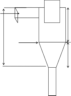
2) Stairmand cyclone configuration was selected for the
Design (see fig 2).
3) The particulate loading of the flue gas in g/m3 was
determined.
4) Diameter (D) of the cylindrical part of the cyclone was
chosen as 200mm.
According to Leith and Litch [11],[12], Collection efficiency of a cyclone may be expressed as;
Particulate exit, Bc=0.375Dc= 0.75m Flue gas exit, DE=0.5Dc= 0.1m Width of gas inlet, a=0.25Dc= 0.5m Height of the gas inlet, b=0.5Dc= 0.1m
DE

1

d
n1
Inlet x-sectional dimension is axb
n 1 exp 1 0.693
pj
j
Where
p 50%
(10)
Dirty gas flow
hc
dp50% = Paricle size with collection efficiency equals 50%
dpj =particles size with collection efficiency other than 50%
dp50% is evaluated as
Hc Dc
0.693
n1

d p50%
A
(11)
A is calculated as,
1

KQ p n 1 2 n1

A 2
18 D2
(12)
Fig 4: Schematic of Stairmand Cyclone
n (vortex exponent) and k are emprical constants, for stairmaid configuration, n=6.4, k =551.3.
Q is the volume flow rate, Dc is cyclone cylindrical diameter, and μ is gas viscosity at temperature in cyclone seperator.
With the considerations of stairmand configuration other physical dimensions of the gas cyclone was calculated as below [12].
Since Dc =0.2m, for stairmand cyclone the following relations hold
Cyclone Height, Hc= 4*Dc = 0.8m
Height of cylinder, hc=1.5Dc= 0.3m
The operating conditions of the gas cyclone were evaluated as follows;
For maximum feed rate fd=6kg/hr, 180g/hr of Ash will be generated with the flue gas stream. Fly ash value is a fraction of the total ash generated; typical value is 60 -70%.[15]. Fly ash is expected to be the major particulate that will be col lected at the gas cyclone.
Q (Volume flow rate o f the flue gases) = mass flow rate of gaseous compt./density
But, Mass of flue gas = mass of the gaseous components + Mass of the particulate.
Mass of flue gas = mass of fluidizing air + mass of fuel
IJSER © 2012 http :// www.ijser.org
Inte rnatio nal Jo urnal o f Sc ie ntific & Eng inee ring Re se arc h Vo lume 3, issue 1, January -2012 7
ISSN 2229-5518
Therefore, maximum mass flowrate (fd=6kghr-1) = 80kg+6kg It is assumed that, density of flue gas=0.746kg/m3 at 200oc Hence Q (Volume flowrate) =116.603m3/hr
From the above and equation (12);
1

551.3x0.0324x1600x7.4 26.41
done with fiberglass insulation held in place by 0.5mm galvanized steel sheets, the thickness of the insulation is
70mm; taking the outer diameter of the combustor to 296mm.
The combustor body is designed to be divided into 2 sections. The Lower section (module 1&2) and upper section (module3,4&5). Each section is properly tightened for rigidity and to prevent leakages. The Top of lower section and bottom of upper section has hinges which allows opening of the upper section for the purpose of viewing the fluidization of the bed at start-up or when need be. A thermocouple placed at the entrance to the gas cyclone measured the flue gas temperature

A=2
= 10.7
(T9) while on line gas analyzer probe is connected to a port on
18x0.23 x2.286x105
µ (Air dynamic viscosity at 200oC) =2.286x10⁻⁵ kg/ms [7] Using the above, dp50% is evaluated.
Subtituting all in equation 1 0, with focus on calculating η(25 µm)
η (25 µm) = 75.4%.
In view of this reasonable efficiency, and bearing in mind that other possible particulates (elutriated bed materials, unburnt fuel particles) are generally larger in size than 25µm, it was concluded that, the dimension chosen for the gas cyclone is appropriate.
So a Stairmand type gas cyclone with Diameter DC =200mm was employed for the BFBC.
10. FABRI CATION AND ASS EMBLY OF PARTS
The combustor body is made from 150mmx2900mm type 304 stainless steel pipe. The body is in modules, each module has 2 flanges machined with projection that match exactly with recess on the adjacent flange.
The base module is closed at one end by means of carbon steel plate( 400mm x 200mm x10mm); which is joined to the foundation frame by 4 M10 -6H bolts
The Distributor plate is sandwiched and effectively locked in place by the base module and the lower end of the second module. The second module dimension (diameter 150mm x
850mm) has openings and attachments for the biomass feeder, the propane gas inlet and the top and the bottom ash ports and Fluidizing air preheating. It also has 2 ports each for thermocouple and manometer.
The Third and fourth modules are exact replica of the second however they have only the thermocouple and manometer ports.
The 5th and the topmost module diameter 150mm x 150mm, has one flange and is covered at the other end. It bears the outlet for the flue gas and the attachment via which the Gas cyclone separator is coupled to the Main body. Lagging is
the flue gas outlet of the gas cyclone.
The centrifugal blower and biomass feeder are positioned on the base frame as shown in fig. 5 The base frame is constructed from welded 45mm carbon steel angle.
(a)
(b)
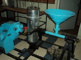
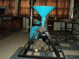
Fig 5:
(a)Picture of the BFBC showing the lower section, the biomass feeder to the right, and centrifugal blower to left all tightly fastened to the base frame,
(b)shows a side view of the BFBC, the upper section of the combustor could be seen at the background.
IJSER © 2012 http :// www.ijser.org
Inte rnatio nal Jo urnal o f Sc ie ntific & Eng inee ring Re se arc h Vo lume 3, issue 1, January -2012 8
ISSN 2229-5518
The control panel is located on the operator side of the BFBC and it house one microcomputer based digital temperature controller XMT*-808 series which sense the temperature via 8 thermocouples placed on the combustor. A Hartmann & Braun AG Temperature controller with analogue display is dedicated to monitoring the inert bed temperature. The H&B AG controller with a fabricated electronic feedback system (inert bed temperature regulating unit) ensure the bed temperature could be fixed to a particular value thus eliminating needs for cumbersome water cooling coil. The control panel also has 10 normally-open push button switch, each connect a thermocouple for zone(1 – 9) to the XMT*808 digital TC, upon closing the current tempera ture of each Zone could be read.


(b)
11. OP ERATION AND T ESTI NG OF T HE BF BC
With all the auxiliary components properly attached the
centrifugal blower was switched on. The Gate Valve was gradually opened until small occasional bubbling was noticed on the surface of the inert bed material (sand particles); this signifies the start of bubbling stage and corresponds to sudden but slight drop in manometer reading. The air flow -rate was further increased to ensure more turbulence; the propane gas valve was gradually opened until the inert bed catches fire from a torch.
At this point the upper section is positioned and securely tightened by means of 6 M10-6H stainless steel bolt.
Fig.6: (a)Microscopy of the sand used as inert bed
(b)A view of inside of the BFBC,
(c)
When the H&B AG controller indicated tha t the temperature of the bed had reached 500oC, the Biomass feeder was switched on to start the combustion process, and then the propane gas was switched off.
After the start-up, fluidizing air flow rate and the biomass feed rate were gradually increased to ensure stable combustion .
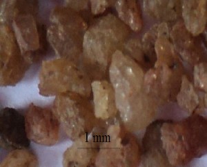
(a) Microscopy of the sand used
(c)shows the control panel with 2 temperature controller and 10
normally-off push button (1 inactive).
The first test-run was done with PKS with biomass feeder motor speed, N=15rpm. At this speed the consumptions was found to be 4.2kg/hr. The inert bed temperature was held steady at 800oC.
During the testing of the BFBC, following measurement were taken
i. the axial temperature along the combustor using Type K
thermocouple
ii. The biomass consumption (kg/hr) for each run was evaluated from the mass of the biomass used and the time it takes to consume it. 4 test-run were done.
12. RES ULTS AND DISCUSSION
12.1 Fuel te sted
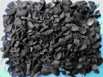
The BFBC was tested with 3kg per batch of ‘as received’ palm kernel shell (PKS) and 3 kg of pulverized coconut shell. The average size of the PKS varied from 4mm-19mm, the coconutshell varied in size from 4 -16mm.The proximate and ultimate analyses were stated earlier in page 3.
IJSER © 2012 http :// www.ijser.org
Inte rnatio nal Jo urnal o f Sc ie ntific & Eng inee ring Re se arc h Vo lume 3, issue 1, January -2012 9
ISSN 2229-5518

set, freeboard temperature however was noticed to be significantly higher withT9 moving from 320 o C to 422oC. This could be explained by the fact that higher fd implies higher volatile combustions in the freeboard and consequently the higher value observed for T4, T5, T6, T7, T8.& T9 See fig 8. A similar result was obtained with CS. It was also observed that the frequency at which the biomass feeder is switched-on and off by the inert bed temperature regulating unit increased markedly with the fd =5.2kg/hr.
Analysis of flue gas composition was not done in this experiments however the flue gas was observed to be clean and transparent in all the tests run done.
(a)
(b)
Fig. 7:(a)Coconut shell sample
(b)PKS sample
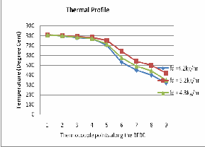
With both fuels, stable combustion was achieved for all the test runs and all the zones show gradual increase in temperature until the inert bed temperature (thermocouple point 2) reached the pre-set temperature of 800oC. With the first experimental run (fd = 4.8kg/hr), the temperature was fairly constant at 800oC from the base of the inert bed to the fourth thermocouple (T4) located 1250mm above the distributor plate. Further up T5, T6, T7, T8 sh ows gradual decrease in temperature and T9 indicated the inlet temperature to the gas cyclone as 320 oC. The thermal profile see fig.8 shows a good agreement with what is seen in the literature [1],[2],[3].
12.2 Effect of feed rate on thermal profile
For the second run the biomass feeder motor speed was increased, combustion of PKS at this speed for 1hr gives a feed rate of 5.2kg/hr. The new feed rate as expected had no effect on the inert bed temperature, since this was already pre-
Fig 8: A plot of thermal profile of PKS in the BFBC at different feed rate. H eight above the distributor plate is represented as thermocouple Zones; Zone 1 represents 80mm above the distributor plate while Zone 9 is exhaust). Uniformity of temperature in Zone 2 is an indication of effectiveness of inert bed temperature regulating unit. The significant thermal difference obtained at exhaust (Zone 9) is an indication of higher volatile combustion in the freeboard for fd = 5.2kg/hr.
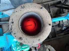
Fig 9: an aerial view of the BFBC during one of the experimental runs. Elutriated particles could be seen on top of the flange of the lower section. Inert bed temperature at this point is 801 oC thus the red color of the inert bed, the dark straight line on top of the bed is the third thermocouple (temp. 627 oC). This is made possible as a result of partioning of the combustor body into lower section and upper section.
13. CONCLUSIONS
The developed BFBC was used to successfully fire PKS and
pulverized CS. Within the limit of the time spent for each
IJSER © 2012 http :// www.ijser.org
Inte rnatio nal Jo urnal o f Sc ie ntific & Eng inee ring Re se arc h Vo lume 3, issue 1, January -2012 10
ISSN 2229-5518
experiment no operational problem was observed in the 4 test- runs. The effectiveness of the inert bed temperature regulating unit strongly indicate that the problem of de-fluidization resulting from ash fusion in the inert-bed could be eliminated since the unit accurately maintained the inert bed temperature at the pre-set value in all the tests.
Fluidizing air pre-heater / Biomass feeding pipe’s cooling attachment was noted to be effective since within the period of testing no problem was experienced with fuel feeding in all the experiments conducted.
The unique partitioning of the modules into lower and upper section help optimized visual observation of the fluidization and combustion of the Biomass at elevated temperature.
In Nigeria there is scarcity of experience on Bubbling Fluidized bed combustion of Biomass , hence success with the developed BFBC could be applied to building experimental models and commercial size BFBC for the purpose of utilizing the abundant biomass resources, in Nigeria and its environ for decentralized energy generation.
ACKNOWL EDGEM ENT
Special thanks to the Managements of Lifeforce Engineering
Company Limited for their support and financial assistance.
REFERENCES
[1] Srinivasa Rao, K.V.N. and Venkat Reddy, G. Effect of secondary air injection on the combustion efficiency of sawdust in a fluidized bed combustor. Brazilian Journal of Chemical Engineering 2008. Vol.25, No 01: 129-141.
[2] Rosyida ,P., Kang, K. H., Mohammad, N. M. J. Emissions Characteristics ofpalm Wastes in Fluidized Bed Combustion. Faculty of Mechanical Engineering, Universiti TeknologiMalaysia, 81310 UTM Skudai, Johor, Malaysia. 2006
[3] Wan,W.A., AbKarim, G., Alias, A.B., and Cliffe,K.R. Co- combustion of refuse derived fuel with coal in a fluidised bed combustor. Journal of Engineering Science andTechnology . Vol.
4,No.1, 122-131. 2009
[4] Suthum P. Fluidised Bed Combustion of Oil PalmSolid Waste.
Waste Incineration Research Center (WIRC). Department of
Mechanical Engineering, King Mongkuts Institute of
Technology North Bangkok. 2004
[5] Wan, W.A., AbKarim, G. R., Mohd Salleh,M.A.,and Alias,A.B.. Air Gasification of Agricultural Waste in a Fluidized Bed Gasifier:Hydrogen Production Performance. Energies 2009, 2,
258-268; doi:10.3390/en2020 0258
[6] Ishbir,S. Design, Development and Testing of a Circulating fluidized bed Combustor for incineration of
Agriwaste. A Thesis submitted in partial fulfillment of the requirements for the award of degree of Master of Engineering in CAD/CAM & Robotics to Thapar Institute of Engineering and Technology, India. 2006
[7] Information on Parameters of air at different temperature and pressure. Retrieved 17-august 2010,from http://www.engineeringtoolbox.com/air-absolute-kinematic- viscosity-d_601.html.
[8] Calculations for screw conveyors. Retrieved April 15,2010, from www.vavnl.com
[9] Hemad Z., Mohammad, H.K., Mohammad R.A., Mahdi Masoomi.
Screw Conveyors Power and Throughput Analysis during
Horizontal Handling of Paddy Grains. Journal of Agricultural
Science2010 . Vol. 2, No. 2.
[10] Hoekstra, A.J., Derksen, J.J., Van Den Akker, H.E.A. An experimental and numerical study of turbulent swirling flow in gas cyclones. Chemical Engineering Science 54, 2055-2065. 1999
[11] Santana,J.D.A.M.,Arnosti,S.Jr.,andCoury, J.R. Performance of cylindrical conical cyclones with different geometrical configurations. Brazilian Journal of Chemical Engineering 2001
Eng. Vol.18 no.3.
[12] Learning about Gas Cyclone. Retrieved august 15, 2010, from http://aerosol .ees.ufl.edu/cyclone/ cyclone.html
[13] Material Bulkdensity: Retrieved on August 20, 2010 from www.asiinstr.com/technical/Material_Bulk_Density_Chart_
[14] Abubakar, S.S. Strategic Developments In Renewable Energy In
Nigeria. International association of energy economics. 2009
[15] UNEP-DTIE Energy Branch: Technical study report on Biomass fired Fluidized bed combustion Boiler Technology for cogeneration. Retrieved on 17 -September, 2010 from http://www.unep.fr/ energy.
[16] Najmi, W.M.W.A., Rosli, A.N. and Izat, M.S. S. Combustion
Characteristics of Palm Kernel Shells Using an Inclined
[17] IPPA : African Case Study: Palm Oil and Economic
Development in Nigeria and Ghana; Recommendations for the World Bank’s 2010 Palm Oil Strategy .Retieved 15July 2010 fromwww.ippanigeria.org
[18] Simeon N. Oka: Fluidized bed combustion. Mercel Dekker Inc.New
York. Page 435, 2004
IJSER © 2012 http :// www.ijser.org