International Journal of Scientific & Engineering Research, Volume 5, Issue 7, July-2014 298
ISSN 2229-5518
Multiobjective Optimal Design of an Axial Flux Permanent Magnet Generator for Directly Coupled Wind Turbines
Narges Taran, Mohammad Ardebili
Abstract— Factors such as high efficiency, high power density, the possibility of realizing a compact multistage machine and the feasibility of applying a large number of poles make the Axial Flux Permanent Magnet (AFPM) generators highly appealing for use as low speed wind power generators. This study puts forth a multi-objective optimization of the efficiency and power density of a low speed AFPM synchronous generator. The optimization problem was formulated by means of general sizing equations and then Genetic Algorithm (GA) was utilized. This study uses a weighted fitness function which offers a tool for ascertaining the priority of objective functions. This fitness function includes two variables whereby an increase in either of them leads to more improvement in one of the objective functions than in the other. The merits of this method are especially palpable in situations where it is necessary to prioritize the objective functions as is indeed the case with generators used in wind turbines which should have not only a high efficiency but also a reduced weight and volume. Finally, the results are verified through the three dimensional Finite Element Method (3D-FEM).
Index Terms— Axial Flux Permanent Magnet (AFPM) machine, Genetic Algorithm (GA), Multi-objective optimization, Synchronous
Generator, Three Dimensional Finite Element Method (3D-FEM).
—————————— ——————————
1 INTRODUCTION
n recent years, Axial Flux Permanent Magnet (AFPM) syn- chronous machines have been growing in popularity and have received an increasing amount of attention in direct drive wind power application [1], [2], [3]. Eliminating the prob- lematic gearbox in direct drive wind turbines decreases the rota- tion speed of the generator shaft. To offset the low speed, there is an inevitable need for a large number of poles and conse- quently a much increased diameter, both of which may be done more easily in axial flux machines than in conventional radial flux ones due to the disc-shape structure of AFPM machines. Other factors such as their high efficiency and high power den- sity make the axial flux permanent magnet generators highly
appealing for use as direct drive wind power generators [4].
AFPM generators are used in a variety of topologies and structures. For instance, they could be single-sided with only one stator and one rotor core, which poses the problem of bal- anced airgap preservation [5]. To solve this problem, the dou- ble-sided structure is used which contains two stator cores and one internal rotor core, known as Axial Flux Internal Rotor (AF- IR), or two rotor cores and one internal stator core, known as the TORUS structure. The ultimate goal of this study is to de- sign a low speed (100 rpm) generator with 1 kW output power. It has been proved that in low power applications the TORUS
————————————————
• Narges Taran is graduated in masters degree program in Power Electron- ics and Electrical Machines in K. N. Toosi University of Technology, Iran. E-mail: nargess_taran@yahoo.com
• Dr. Mohammad Ardebili is currently head of Electrical Power Engineering
Department of K. N. Toosi University of Technology, Tehran, Iran.
Email: ardebili@eetd.kntu.ac.ir
structure yields a higher power density [6]. The stator core could be slotted or slotless while the slotted stator results in a lower airgap and magnet thickness and also a higher mechani- cal strength in the winding configuration [7]. The rotor core could have surface mounted Permanent Magnet (PM)s or em- bedded PMs. Given the centrifugal force, embedded PMs are a better choice whereas considering the low speed in direct drive applications as well as the need for placing a high number of PMs makes it more practical to use surface mounted PMs. Fig. 1 illustrates an AFPM generator with the TORUS-S (double rotor and slotted stator) structure and surface mounted PMs.
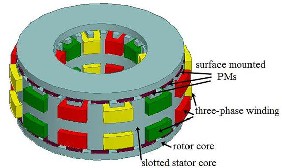
Fig. 1. TORUS-S generator
Regarding the construction of AFPM machines, different cross sections in different axial lengths will lead to different views. Considering radial cross sections will not solve the prob- lem because the flux density varies with different diameters. To tackle this obstacle, some studies employ the quasi-3D method which applies two dimensional analysis of AFPM machines in the mean diameter [8], [9], [10]. Compared with the three di- mensional Finite Element Method (3D-FEM), the results ob- tained from the quasi-3D are not sufficiently accurate. The only drawback of 3D-FEM is that it is time-consuming. This study
IJSER © 2014 http://www.ijser.org
International Journal of Scientific & Engineering Research, Volume 5, Issue 7, July-2014 299
ISSN 2229-5518
applies 3D-FEM as an assistant design tool simulation principle.
A 1 kW, 100 rpm AFPM generator consisting of 20 poles and
𝐷𝑜 = ( 𝜋

𝑃𝑜𝑢𝑡
𝑓

1
1 + 𝜆 )3 (6)
24 slots was designed and, using Genetic Algorithm (GA), its efficiency and power density were simultaneously improved to the optimized amounts.
2 DESIGN OF TORUS-S GENERATOR
2.1 General Sizing Equations
Output power for any electrical machine can be expressed as
[11]

𝑚 𝑇
𝑃𝑜𝑢𝑡 = 𝜂 𝑇 � 𝑒(𝑡)𝑖(𝑡)𝑑𝑡 = 𝜂𝑚𝑘𝑝 𝐸𝑝𝑘 𝐼𝑝𝑘 (1)
where m represents the number of phases and e(t) and Epk
stand for the phase air-gap EMF and its peak value. The cur- rents i(t) and Ipk are the phase current and the peak phase cur-
rent, and T is the period of one EMF cycle. The factor Kp signi-
fies the electrical power waveform which equals 0.5cosφ for a sinusoidal design; cosφ is the power factor [12].
The EMF peak value in (1) for the axial flux machines is
reached through
2 𝑘𝑒 𝑘𝑖 𝑘𝑝 𝜂𝐵𝑔 𝐴 𝑝 (1 − 𝜆2) 2
Inner diameter could be derived by the product of Do and
λ. The value of λ and its effect on the generator performance
has been investigated by several articles. In practice, the opti-
mal value for λ may differ depending upon the optimization
goal. Moreover, given different electrical loading and flux
densities, even when the optimization criterion remains unal-
tered, the optimal value for λ can vary according to the rated
power, number of poles, frequency, etc. [15], [16], [17]. In the present study, the selection of the best value for λ was made by the optimization part.
The total axial length of the TORUS-S could be calculated by
𝐿𝑎𝑥 = 𝐿𝑠 + 2𝐿𝑟 + 2𝑔 (7)
where Lax stands for the total axial length, Ls and Lr are stator
and rotor total thickness and g indicates one of the two airgap lengths. Ls can be expressed as
𝐿𝑠 = 𝐿𝑐𝑠 + 2𝑑𝑠𝑠 (8)
where Lcs is the stator core length and dss the stator slot depth.
Equations (9) and (10) present them as
𝐵𝑔 𝜋𝛼𝑝 𝐷𝑜 (1 + 𝜆)

𝑓 𝐿𝑐𝑠 =
(9)
𝐸𝑝𝑘 = 𝑘𝑒 𝑁𝑝ℎ 𝐵𝑔 2𝑝 (1 − 𝜆 )𝐷𝑜
(2)
4𝑝𝐵𝑐𝑠

2𝐴𝐷𝑚
where Ke is the EMF factor which incorporates the winding distribution factor (Kw ) and the per unit portion of the total air gap area spanned by the salient poles of the machine (if any)
𝑑𝑠𝑠 =

𝐷𝑖 − �𝐷𝑖 2 −
2

𝑘𝑐𝑢 𝐽𝑤
(10)
[13], Nph the number of turns per phase, Bg flux density in the air gap (also known as specific magnetic loading), f the fre-
quency, p the number of poles, Do the outer diameter of the machine, and λ is inner diameter to outer diameter ratio
(λ = Di ⁄Do ) referred as diameter ratio while Di represents the
inner diameter of the machine.
The peak phase current in (1) is calculated as
where αp is the ratio of the pole-arc to pole-pitch, kcu the slot fill factor and Jw the current density in the stator winding. Slot depth dss has been calculated in the mean diameter because
the slots are parallel-sided. Accordingly, increasing the diame-
ter leads to the widening of the tooth width, thus producing
the smallest tooth width in the inner diameter. Thus, satura-
tion starts from the inner diameter. In order to take the satura-
𝐼𝑝𝑘 = 𝐴𝜋𝑘𝑖

1 + 𝜆
2
𝐷𝑜
2𝑚 𝑁
(3)
tion hazard into account, the slot dimension calculations should be carried out in the inner diameter. Bcs is the stator
1 𝑝ℎ
where m1 indicates the number of phases in each stator and Ki
is the current waveform factor whose value for the sinusoidal

wave form is √2. The linear current density in the mean diam-
eter known as the specific electrical loading could be calculat-
ed as follows:
𝑚𝐼𝑟𝑚𝑠 2𝑁𝑝ℎ
core maximum flux density which, for the TORUS structure,
can be estimated by (11) [17].
5.47 𝑓−0.32 𝑓 > 40 𝐻𝐻
𝐵𝑐𝑠 = � 1.7 𝑡𝑡 1.8 𝑓 ≤ 40 𝐻𝐻 (11)
The rotor axial length, Lr , becomes
𝐿𝑟 = 𝐿𝑝𝑚 + 𝐿𝑐𝑟 (12)
𝐴 =
𝜋𝐷𝑚
Di+Do

(4)
Lpm is the magnet thickness, and Lcr which is the rotor core axial length can be expressed as

where Dm presents the mean diameter (D = ).
2
𝐿𝑐𝑟 =

𝐵𝑔 𝜋𝐷𝑜 (1 + 𝜆)
(13)
Combining (1) through (3), the general purpose sizing
equation takes the following form for AFPM:
8𝑝𝐵𝑐𝑟
B is the rotor core maximum flux density and for the TORUS
𝑚 𝜋
𝑓
2 1 + 𝜆 3
cr
structure has been estimated to be between 1.6 T to 1.8 T [17].

𝑃𝑜𝑢𝑡 = 𝑚
𝑘𝑒 𝑘𝑝 𝑘𝑖 𝐴𝐵𝑔 𝜂 (1 − 𝜆 )
2 𝑝
𝐷𝑜
2
(5)
2.2 Sizing Equations for the TORUS-S
The generalized sizing equation approach can easily be ap- plied to AFPM TORUS type generators [14].
2.3 Calculating the Efficiency
Machine efficiency can be expressed as
𝑃𝑜𝑢𝑡
From (5) the outer diameter can be calculated as

𝜂 =
𝑃𝑜𝑢𝑡
+ 𝑃𝑐𝑢
+ 𝑃𝐹𝑒
+ 𝑃𝑚
(14)
where Pcu , PFe and P m represent the copper, iron and mechan-
IJSER © 2014 http://www.ijser.org
International Journal of Scientific & Engineering Research, Volume 5, Issue 7, July-2014 300
ISSN 2229-5518
ical losses, respectively. Mechanical losses, being an insignifi- cant fraction of total losses, were not taken into account [18]. The copper losses consist of ohmic and eddy current losses in wires as shown in (15).
𝑃𝑐𝑢 = 𝑃𝑅𝐼2 + 𝑃𝑐𝑢,𝑒𝑑𝑑𝑦 (15)
The ohmic loss was calculated using the phase resistance
Rph and the phase current Iph by (16).
𝑃𝑅𝐼2 = 3𝑅𝑝ℎ𝑎𝑠𝑒 𝐼2 (16)
Phase resistance can be calculated as follows
𝜌𝑐𝑢 𝐿𝑝ℎ𝑎𝑠𝑒
3 SLOT AND POLE NUMBER COMBINATION
3.1 Choosing an optimal number of slots and poles to achieve a high winding factor
The number of stator slots and rotor poles should be selected properly to obtain suitable winding configuration. A good winding configuration must fulfill the following requirements:
- the winding factor has to be high enough so that the rated power of the generator is not reduced;
- it must make the best use of wires and avoid long end windings so that copper loss does not increase;
𝑅𝑝ℎ =
𝑎𝑐𝑢

(17)
- it must reach the best copper utilization factor in the
slots; and
where ρcu is the copper resistivity, acu the conductor cross sec- tion, and Lphase the conductor length per phase which, for a TORUS-S machine with coil pitch equal to one tooth (tooth concentrated winding configuration), can be calculated by
𝐿𝑝ℎ𝑎𝑠𝑒 = 𝑁𝑝ℎ (𝐿 + 𝑊𝑡𝑖 + 𝑊𝑡𝑜 ) + 𝜋𝐷𝑜 (18)
Equation (18) is illustrated in Fig. 2. Wti and Wto stand for
the tooth width in the inner and outer diameter and L repre-
sents the effective length of each coil which could be calculat-
ed through outer and inner diameter subtraction.
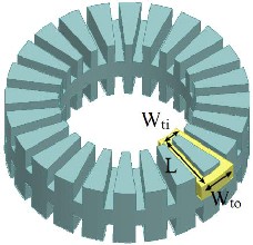
Fig. 2. The total length of a coil
Eddy current loss in winding can be calculated as
𝑃𝑐𝑢,𝑒𝑑𝑑𝑦 = 𝐾𝑐𝑢,𝑒𝑑𝑑𝑦 𝑓2 𝐵𝑔 2 (19)
where Kcu,eddy is dependent on wire material and its volume.
Iron loss could be calculated by equation (20) which divides it
into hysteresis, eddy current and an excess loss components:
𝑃𝐹𝑒 = 𝑘ℎ 𝑓𝐵𝑝 𝛼 + 𝑘𝑒 𝑓2 𝐵𝑝 2 + 𝑘𝑒𝑥𝑐 𝑓1.5 𝐵𝑝1.5 (20)
In the above equation, Bp represents the peak flux density
in the teeth. kh , ke and kexc factors are dependent on the se- lected material and volume.
2.4 Calculating the Power Density
Upon calculating the main Dimensions, it becomes possible to calculate the power density through (21):
𝑃𝑜𝑢𝑡
- it must obtain a sinusoidal distribution of the MMF in order to avoid torque pulsations [19].
In low speed machines, eddy current losses are naturally small and there is no need to use complicated distributed winding which will result in unwanted copper losses. Over- lapping and increasing coil pitch will lead to a longer length of inactive wire. Double-layer windings have a lower winding factor and copper fill factor. Therefore, a single-layer non- overlapped tooth concentrated winding (coil pitch equals one tooth) will be the simplest and most suitable configuration. It could be easily shown that the winding factor will be less than
0.866, which is not an ideal result, unless the value for the slot per pole per phase (q) falls between 0.25 and 0.5 [19], [20], [21]. As for the slot-pole number, a suitable combination should fulfill the following requirements:
- the number of slots should be an even number and a multiplier of the number of phases;
- the number of coils for each phase and the number of turns per coil should be an integer number;
- the Greatest Common Devisor (GCD) between the number of poles and slots indicates the number of times a winding configuration is repeated. Conse- quently, to obtain a balanced winding, the number of slots per phase should be divisible by GCD{ns,p}
When a DC output is required, the AC output of the gener- ator is rectified so that no particular frequency of machine EMF is demanded. To have a frequency in the range of 15 to
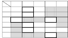
25 Hz, with a generator speed of 100 rpm, the pole number should be in the range of 18 to 30. Table 1 represents accepta- ble combinations of slot-pole numbers and their correspond- ing fundamental winding factors. The bolded cells show the highest winding factor for each pole number candidate.
TABLE 1
WINDING FACTORS FOR DIFFERENT SLOT-POLE COMBINATION

𝑃𝑑𝑒𝑛𝑠𝑖𝑡𝑦 = 𝜋
4 𝐷𝑡
2 𝐿𝑎𝑥
(21)
where DRt Ris the total outer diameter, encompassing the wind- ing thickness.
IJSER © 2014 http://www.ijser.org
International Journal of Scientific & Engineering Research, Volume 5, Issue 7, July-2014 301
ISSN 2229-5518
3.2 Choosing an optimal number of slots and poles to achieve a low cogging torque
The next step is considering the impact of the slot-pole combi- nation on the cogging torque. The cogging torque results from the magnetic force which attempts to maintain the alignment between the stator teeth and the permanent magnet poles. Therefore, the higher the number of poles and slots, the higher the cogging torque; and the higher the Least Common Multi- ple (LCM) between pole and slot numbers, the lower the cog- ging torque. The factor CT was introduced to denote the suit- ability of the slot-pole combinations in terms of the cogging torque [22]:
𝑝𝑛𝑠
i. Random generation of the initial population;
ii. Evaluation of the fitness of each chromosome;
iii. Termination condition or final generation (If YES,
display superior chromosome. If NOT, go to next
step);
iv. Reproduction of a new population using selection,
mutation and crossover operators. v. Back to step ii.
To use GA, it is necessary to specify a number of parame- ters as the genes constituting the chromosomes and to intro- duce objective functions into the algorithm via fitness func- tion. In introducing the genes, it should be kept in mind that
the parameters are not interconnected. The present study se-
𝐶𝑇 =
𝐿𝐶𝑀

(22)
lected five parameters as genes: namely, specific magnetic
where p represents the number of poles, ns the number of slots and LCM the Least Common Multiple between ns and p. The larger the CT factor, the larger the cogging torque.
Table 2 presents different possible combinations for the number of poles and slots for a single-layer tooth concentrated winding with corresponding winding factors and CT factors. The selected combination contains 20 poles and 24 slots which leads to a high winding factor as well as a small CT.
TABLE 2
THE CT FACTOR FOR DIFFERENT POLE-SLOT COMBINATIONS
loading, outer diameter, inner to outer diameter ratio, pole- pitch to pole-arc ratio and number of turns per phase. The parameters not selected as genes may be easily calculated through the equations mentioned above and the values as- signed to the genes.
This study incorporates Genetic Algorithm to maximize
both the efficiency and power density. The genes are chosen in
a way that not only the parameters independent from one an-
other but also the ones exerting the greatest influence on the
objective function will be selected. Table 3 represents the gen-
erator characteristics and the selected genes as well as their
restrictions in terms of efficiency and power density optimiza-
tion.
TABLE 3
DESIGN REQUIREMENTS AND OPTIMIZATION RESTRICTIONS
4 GENETIC ALGORITHM OPTIMIZATION
Due to the multiplicity of parameters involved in the design and the nonlinear equations complicating the relationship among the parameters, the problem at hand will not yield an optimized outcome through manual design, requiring soft computing methods. Genetic Algorithm (GA) is one of the most widely used population-based methods and stochastic search techniques. Its ability to search in vast, multi- dimensional spaces and its nonlinear nature make it indispen- sable to the optimization of electrical machines.
The optimization problem is expressed in terms of a set of parameters X= {xR1R, xR2R, …, xRnR} where f(x), the objective func- tion, can yield a maximum and minimum value. Utilizing simulated evolution, the solution space of the function is searched by the GA. In this case, X is referred to as a chromo- some and xR1R, xR2R, …, xRnR as genes. The combination of the three basic operators – that is, selection, crossover, and mutation – is used in the GA in order to simulate the evolution process. The fittest chromosomes in any population tend to reproduce and survive to the next generation, which helps improve subse- quent generations [23]. The GA optimization method consists of the following steps:
In order to execute the optimization algorithm, MATLAB’s R2011a software optimization toolbox was used. Multi- objective GA is not very useful with regard to improving both of the selected objective functions via MATLAB’s optimization toolbox. The reason is that the multi-objective optimization algorithm totalizes all objective functions attempting to in- crease the total sum of all objectives. Since the power density (expressed in W/cm3) is smaller than the efficiency (expressed in percentage), the final result of the optimization, leading to higher improvement in the objective function with a lower value, improves the power density much more than the effi-
IJSER © 2014 http://www.ijser.org
International Journal of Scientific & Engineering Research, Volume 5, Issue 7, July-2014 302
ISSN 2229-5518
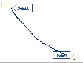
ciency. Fig. 3 shows the Pareto front achieved through the multi-objective method conducted in MATLAB’s optimization toolbox. The horizontal axis represents efficiency in a way that moving to the left on the Pareto front curve increases the im- provement on efficiency. The vertical axis represents power density in a way that moving to lower parts of the curve re- sults in higher improvements on power density. As a result, the largest power density is obtained at point A which con- tains the lowest efficiency, and the highest efficiency is achieved at point B where power density is lowest. Table 4
density corresponding to a/b ratios of 1 to 6. According to Fig.
4, one of the best compromises is achieved when a/b ratio
equals 4.2. Therefore, a/b=4.2 was selected to execute the op-
timization algorithm. Of course, this selection is highly de-
pendent on turbine necessities and the restrictions imposed on
the suitable generator.
86
represents the values for point A and B more clearly. 84
optimum efficiency v.s. a/b ratio
0
-0.1
-0.2
X: -80.19
Y: -0.09186
Pareto front
82
80
78
0.41 1.5 2 2.5 3 3.5 4 4.5 5 5.5 6
-0.3
-0.4
-0.5
0.3
0.2
0.1
0
optimum power density v.s. a/b ratio
-0.6
-0.7
X: -27.19
Y: -0.6687
1 1.5 2 2.5 3 3.5 4 4.5 5 5.5 6
a/b ratio
Fig. 4. Objective functions vs. a/b ratio
-90 -80 -70 -60 -50 -40 -30 -20
Objective 1: -efficiency [%]
Fig. 3. Pareto Front for the multi-objective optimization
TABLE 4
VALUES FOR THE PARETO FRONT CRITICAL POINTS
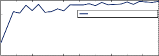
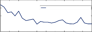
Since MATLAB’s optimization toolbox only seeks out the
minimum value, the fitness function was introduced to opti- mize the negative amount of (23). Fig. 5 shows that for a popu- lation of 400 for each generation, the fitness function converg- es after 500 generations. Table 5 presents the detailed specifi-
cations of the optimized slotted TORUS generator.
-3.4
Best fitness
As Fig. 3 and Table 4 demonstrate, at point A the power density is very large but the efficiency is very low and thus unacceptable, while at point B the power density is high but the efficiency is still not sufficiently high. Therefore, the effi- ciency cannot be either of the suggested points obtained from the search space because neither is high enough. In other words, the multi-objective optimization is unable to optimize both objective functions, especially when their numerical val- ues are from different levels with one of them being consider- ably smaller than the other. To tackle this obstacle, the follow- ing fitness function was introduced:
𝐹𝑖𝑛𝑡𝑛𝑒𝑠𝑠 𝐹𝑢𝑛𝑐𝑡𝑖𝑡𝑛 = 𝑎 ∗ 𝜂 + 𝑏 ∗ 𝑃𝑑𝑒𝑛𝑠𝑖𝑡𝑦 (23)
An increase in “a” leads to a greater emphasis on the effi-
ciency so that the optimization process will improve the effi-
ciency more than the power density while a rise in “b” leads to
a greater emphasis on the power density so that the optimiza-
tion process will improve the power density more than the
efficiency. Nevertheless, the two parameters are not complete- ly independent and the a/b ratio is significant. Fig. 4 displays the varying amounts of increase in the efficiency and power
IJSER © 2014 http://www.ijser.org
-3.5
-3.6
-3.7
-3.8
-3.9
0 50 100 150 200 250 300 350 400 450 500
Generation
Fig. 5. Fitness function variation during GA optimization
International Journal of Scientific & Engineering Research, Volume 5, Issue 7, July-2014 303
ISSN 2229-5518
TABLE 5
THE OPTIMIZED GENERATOR SPECIFICATIONS
Magnetic loading (Bg ) | 0.79 [T] | Magnet thickness (Lpm ) | 4 [mm] |
Outer diameter (D o ) | 0.22 [m] | Stator core axial length (L cs ) | 10.3 [mm] |
Pole arc/pole pitch (α p ) | 0.65 | Rotor core axial length (L cr ) | 11 [mm] |
Inner/outer diam- eter (λ) | 0.45 | Total axial length (Lax ) | 120.5 [mm] |
Number of turns/phase (N ph ) | 456 | Flux per pole per phase (φ pp ) | 0.88 [mWb] |
Specific electric loading (A) | 25.3 [kA/m] | EMF (Ephase ) | 25.28 [v] |
Current density (J w ) | 3.5 [A/mm2 ] | Resistance per phase (R phase ) | 0.64 [Ω] |
Slot width (w s ) | 10 [mm] | Synchronous reac- tance (X syn ) | 12.23 [Wb] |
Slot depth (d ss ) | 28 [mm] | Power density | 0.14 [W/cm3] |
Airgap (g) | 1 [mm] | Efficiency (η) | 86.66 [%] |
5 SIMULATION RESULTS
The performance of the generator was investigated using three dimensional finite element analysis and verified by Maxwell
14.0 3D simulation.
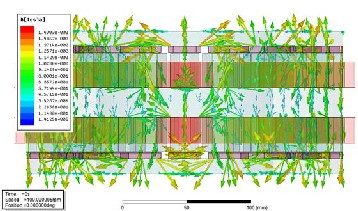
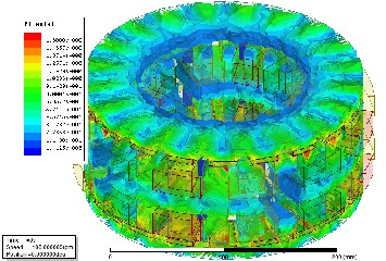
Figure 6 illustrates the flux density distribution and Fig. 7
its direction. It is evident that flux density is higher in close
proximity to the PMs. The flux direction represents that oppo-
site PMs are facing different poles (NS configuration for
poles).
Fig. 7. Flux directions
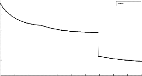
Core and teeth saturation adversely affects the operation of the machine because it reduces machine efficiency. To detect the saturation of either the core or the teeth, moreover, it is necessary to assess the magnetic flux density of the designed AFPM machine. Fig. 8 shows the air-gap flux density distribu- tion with an average radius over two pole pairs. Fluctuations are due to inevitable phenomena such as the anisotropy of the rotor core and magnets. Also, the slotted stator increases dis- tortions as well.
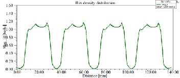
Fig. 8. Flux density in airgap over two pole pairs
The sinusoidal flux linkage obtained through a 180° rota- tion is depicted in Fig. 9.
0.75
0.50
0.25
0.00
-0.25
-0.50
flux 180 degree

load RC - 0A_sd_sCteuprv1e.5In_f orotate360 ANSOFT
FluxLinkage(phaseA) Setup1 : Transient
FluxLinkage(phaseB) Setup1 : Transient
FluxLinkage(phaseC) Setup1 : Transient
Fig. 6. Flux density distribution
-0.75
0.00 50.00 100.00 150.00 200.00 250.00 300.00
Time [ms]
Fig. 9. Flux linkage waveforms
IJSER © 2014 http://www.ijser.org
International Journal of Scientific & Engineering Research, Volume 5, Issue 7, July-2014 304
ISSN 2229-5518
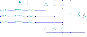
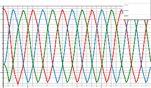
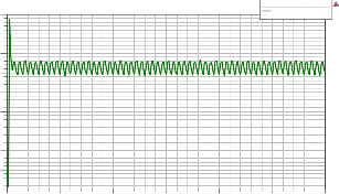
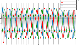
A three-phase bridge diode rectifier has been used to obtain the DC voltage. The load is a 100 ohm resistor placed in paral- lel to a low pass filter with the value of 220 μF in order to de- crease the output DC voltage ripple. Fig. 10 presents bridge rectifier. The two stator side windings are connected in series and the star connection is used to avoid circulating currents. Obtained three-phase EMF whose rms amount is approxi- mately 45v has been illustrated in Fig. 11.
Model
160.00
140.00
120.00
100.00
80.00
60.00
40.00
20.00
0.00
DC voltage without capacitor
load R - 0A_sd_stCeupr1ve.5In_frootate360
ANSOFT
NodeVoltage(IVoltmeter18)
Setup1 : Transient
diodemod
D49
D51
D53
-20.00
0.00 100.00 200.00 300.00 400.00 500.00 600.00
LphaseA
LphaseB
0.000173H L43
0.000173H L44
0.03326ohm
R46
0.03326ohm
R47
220uF C58
R57
100ohm
LabelID=IVoltme
Time [ms]
Fig. 12. Output DC voltage without LPF
LphaseC
0.000173H L45
0.03326ohm
R48
D50
D52
D54
0
150.00
125.00
DC voltage with 220 uF capacitor
load RC - 0A_sd_steCpur1v.e5_Inrf o ate360
ANSOFT
NodeVoltage(IVoltmeter56)
Setup1 : Transient
Fig. 10. Diode bridge rectifier
100.00
100.00
75.00
50.00
25.00
0.00
-25.00
-50.00
-75.00
induced voltage
load RC - 0A_sd_sCteuprv1e.5In_f orotate360
ANSOFT
InducedVoltage(phaseA) Setup1 : Transient
InducedVoltage(phaseB) Setup1 : Transient
InducedVoltage(phaseC) Setup1 : Transient
75.00
50.00
25.00
0.00
-25.00
0.00
600.00
-100.00
0.00 100.00 200.00 300.00 400.00 500.00 600.00
Time [ms]
Fig. 11. The three-phase induced voltage (EMF)
According to (24) the resultant DC voltage should be about
110v.
3.75
1.75
-0.25
three phase current through 180 degree rotation
Curve Inf o
Current(phaseA) Setup1 : Transient
Current(phaseB) Setup1 : Transient
Current(phaseC) Setup1 : Transient

ANSOFT


𝑉𝑑𝑐 = √3𝑉𝑚 = √3√2𝑉𝑟𝑚𝑠 (24)
where Vm is the maximum induced three-phase voltage.
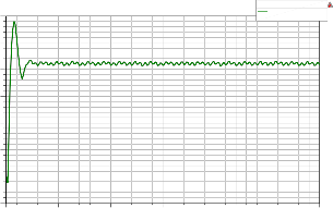
The parallel capacitor works as a Low Pass Filter (LPF) in
order to reduce the output DC voltage ripples. To illustrate
this point, Fig. 12 represents the output DC voltage while
there is no LPF and the ripple is about 15 v and Fig. 13 ex-
presses the output DC voltage with a 220 μF capacitor paral-
leled with a 100 ohm load where the ripple has been reduced
to one third, i.e. 5 v. Although by increasing the amount of the
capacitor it is possible to decrease the DC voltage ripple, it will
result in a high amount of current on diodes that could dam-
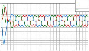
age them. Fig. 14 depicts the three-phase current through a 180 degree rotation.
-2.25
-4.25
-6.25
0.00 50.00 100.00 150.00 200.00 250.00 300.00
Time [ms]
Fig. 14. Three-phase current waveform
6 CONCLUSION
The generator is the heart of any wind turbine and optimization may be said to be the most important part of its design and manufacture. Being fully compatible with wind turbine re- quirements, Axial Flux Permanent Magnet generators enjoy increasing popularity in the industry. In this paper, the design of a 1 kw, 100 rpm Axial Flux Permanent Magnet synchronous generator with TORUS-S structure for application in direct drive wind turbines is presented. A variety of slot-pole combi- nations were fully explored and the most suitable of them was selected (20 poles and 24 slots), leading to the lowest cogging torque and the highest efficiency. Single-objective optimizations
IJSER © 2014 http://www.ijser.org
International Journal of Scientific & Engineering Research, Volume 5, Issue 7, July-2014 305
ISSN 2229-5518
have already been the focus of a number of articles, but the simultaneous optimization of two essential parameters, efficien- cy and power density, has rarely been discussed. This paper offers a novel objective function via Genetic Algorithm to opti- mize the design of an AFPM generator with a TORUS-S topolo- gy. This objective function enables the optimization algorithm to favor efficiency over power density or vice versa. The ability to control the optimization focus allows the designer to achieve the optimum balance between the weight and size, on the one hand, and efficiency, on the other, depending on the location of the turbine and other similar factors which must be considered in the design. Therefore, the final result could be more suitable for this special purpose. Subsequently, the performance of the optimized generator was examined by finite element analysis three dimensional simulation. The results met the expected magnitudes which fully agree with the desired values.
Finally, it is worth mentioning that the design procedure and multi-objective optimization discussed in this paper is compre- hensive and therefore easily applicable for similar design goals with different optimization objectives as well.
7 REFERENCES
[1] Soderlund, L., Koski, A., Vihriala, H., Eriksson, J-T., Perala, R., “De- sign of an Axial Flux Permanent Magnet Wind Power Genera- tor”, Eighth International Conference on Electrical Machines and Drives, (Conf. Publ. No. 444) , vol., no., pp.224,228, 1-3 Sep 1997.
[2] Chalmers, B.J., Wu, W., Spooner, E., “An Axial Flux Permanent Mag- net Generator for a Gearless Wind Energy System”, Proceedings of International Conference on Power Electronics, Drives and Energy Systems for Industrial Growth, , vol.1, no., pp.610, 8-11 Jan 1996.
[3] Wang, F., Pan, J., Zhang, Y., Cai, X., Liu, Y., Li, C., Du, J., “Design and Performance of Large Scale Direct-Driven Permanent Magnet Wind Generators”, International Conference on Power Engineering, Ener- gy and Electrical Drives (POWERENG), vol., no., pp.1,5, 11-13 May
2011.
[4] Spooner, E., Chalmers, BJ., “TORUS-Slotless, Toroidal-Stator, Perma- nent Magnet Generator”, IEE proceedings-B electric power applica- tions , Vol. 139, No.6, pp. 497-506, 1992.
[5] Eastham, J.F., Balchin, M. J., Betzer, T., Lai, H.C., Gair, S., “Disk Mo- tor with Reduced Unsprung Mass for Direct EV Wheel Drive”, IEEE Int. Symp. On Industrial Electronics, 1995.
[6] Profumo, F., Zhang, Z., Tenconi, A., “Axial Flux Machines Drives: A New Viable Solution for Electric Cars”, IEEE Transactions on indus- trial electronics, Vol. 44, No.1, pp. 39-45, 1997.
[7] Zhang, Z., Profumo, F., Tenconi, A., “Axial Flux Wheel Machines for Electric Vehicles”, IEEE Trans. on Electric Machines and Power Sys- tems, 1996.
[8] Parvianien, A., Niemela, M., Pyrhonen, J., “Modelling of Axial Flux Permanent Magnet Machines”, IEEE Transaction on industry appli- cations, Vol. 40, No.5, pp. 1333-1340, 2004.
[9] Wibowo, H. A., Pradikta, A., Dahono, P.A., “An Analysis of Slotless Axial Flux Permanent Magnet Generators”, Power Engineering and Renewable Energy (ICPERE), 2012 International Conference on , vol., no., pp.1,6, 3-5 July 2012.
[10] Ji-Young Lee, Dae-Hyun Koo, Seung-Ryul Moon, Choong-Kyu Han, “Design of an Axial Flux Permanent Magnet Generator for a Portable Hand Crank Generating System”, IEEE Transactions on Magnetics,
vol.48, no.11, pp.2977,2980, Nov. 2012.
[11] Huang, S., Luo, J., Leonardi, F., Lipo, T. A., “A General Approach to Sizing and Power Density Equations For Comparison Of Electrical Machines” , IEEE Trans. Ind. Appl., vol. 34, no. 1, pp. 92–97, Jan./Feb. 1998.
[12] Mahmoudi, A., Kahourzade, S., Rahim, N.A., Hew, W.P., “Design, Analysis, and Prototyping of an Axial Flux Permanent Magnet Motor Based on Genetic Algorithm and Finite Element Analy- sis”, Magnetics, IEEE Transactions on , vol.49, no.4, pp.1479,1492, April 2013.
[13] Gholamian, A., Ardebili, M., Abbaszadeh, K., “Selecting of Slotted AFPM Motors with High Torque Density for Electric Vehicles”, In- ternational Journal of Scientific & Engineering Research Volume 2, Issue 6, June 2011.
[14] Aydin, M., Huang, S., Lipo, T.A., “Design and 3D Electromagnetic Field Analysis of Non-Slotted and Slotted TORUS Type Axial Flux Surface Mounted Permanent Magnet Disc Machines”, IEEE Interna- tional Electric Machines and Drives Conference, IEMDC, vol., no., pp.645,651, 2001.
[15] Camplell, P., “Principle of a Performanent Magnet Axial Flux DC Machine”, Proc.Inst. Elec.Eng,. vol. 121, No. 12, Dec. 1974.
[16] Jensen, C. C., Profumo, F., Lipo, T. A., “ A Low Loss Permanent Magnet Brushless DC Motor Utilizing Tape Wound Amorphous Iron”, IEEE Transactions On Industry Applications, vol. 28, No 3, pp
646-651, May/June. 1992.
[17] Huang, S., Luo, J., Leonardi, F., Lipo, T. A., “A Comparison of Power Density for Axial Flux Machines Based on the General Purpose Siz- ing Equation”, IEEE Transactions on Energy Conv., vol. 14, Jan. 1999.
[18] Vansompel, H., Sergeant, P., Dupre, L., “Optimized Design Consid- ering The Mass Influence of an Axial Flux Permanent Magnet Syn- chronous Generator with Concentrated Pole Windings”, IEEE Transactions on Magnetics, vol.46, no.12, pp.4101,4107, Dec. 2010.
[19] Skaar, S. E., Krøvel, Ø., Nilssen, R., “Distribution, Coil-Span and
Winding Factors for PM Machines with Concentrated Windings”, Norwegian Research Council, Norway, 2006.
[20] Cistelecan, M.V., Popescu, M., Popescu, M., “Study of the Number of Slots/Pole Combinations for Low Speed Permanent Magnet Syn- chronous Generators”, IEEE International Conference on Electric Ma- chines & Drives Conference, 2007. IEMDC, May 2007.
[21] Florence Meier, “Permanent-Magnet Synchronous Machines with Non-Overlapping Concentrated Windings for Low-Speed Direct- Drive Applications”, PhD thesis, Royal Institute of Technology, Stockholm, Sweden, 2008.
[22] Zhu, Z.Q., Howe, D., “Influence of Design Parameters on Cogging Torque in Permanent Magnet Machines”, IEEE Transactions on En- ergy Conversion, , vol.15, no.4, pp.407,412, Dec 2000.
[23] Wrobel, R., Mellor, P.H., “Design Considerations of a Direct Drive Brushless Machine with Concentrated Windings”, IEEE Transactions on Energy Conversion, vol.23, no.1, pp.1,8, March 2008.
IJSER © 2014 http://www.ijser.org