International Journal of Scientific & Engineering Research, Volume 4, Issue 12, December-2013 318
ISSN 2229-5518
Multi Level Inverters based control of Permanent
Magnet Synchronous Machine
PRATYUSHA KADIYALA, GRANDHI RAMU Electrical and Electronics Engineering Department, Chaitanya Institute of Science and Technology, Kakinada, A.P, India.
ABSTRACT:
Multilevel inversion is a power conversion strategy in which the output voltage is obtained in steps thus bringing the output closer to a sine wave and reduces the Total Harmonic Distortion. Multilevel inverter structures have been developed to overcome shortcomings in solid-state switching device ratings so that they can be applied to higher voltage systems. In recent years, the multilevel inverters have drawn tremendous interest in the area of high-power medium-voltage energy control. Three different topologies have been proposed for multilevel
inverters like Diode-Clamped Inverter, Capacitor
rare-earth magnets is only slightly above unity, the effective air gap becomes long with a surface magnet construction[6][7]. This makes the direct-axis inductance very low, which has a substantial effect on the machine’s overloading capability, and also on the field weakening characteristics. As the pull-out torque is inversely proportional to the daxis inductance, the pull-out torque becomes very high. Typically, the per-unit values of the d- axis synchronous inductances of the PMSM vary between
0.2−0.35 p.u., and consequently the pull-out torque is in the range of 4−6 p.u., which makes them well suitable in motion control applications.
Speed control of PMSM system is equipped with
an adjustable frequency drive that is a power electronic
IJSER
Clamped Inverter and Cascaded Multi cell Inverter. In
addition, several modulation and control strategies have been developed or adopted for multilevel inverters including the following multilevel Sinusoidal Modified SVPWM is applied for Three-Level Inverter and Five- Level Inverter. The best modulation techniques are extended to Permanent Magnet Synchronous Motor.
INTRODUCTION:
The use of variable speed drives in industry is on
increase. Highly efficient drives are costly to manufacture as well as provide difficulty in maintenance. The conventionally used 3-phase induction motor is a constant speed motor, and with the help of drives the motor can be used for variable speed applications, but at the cost of reduced efficiency.[1][2][3] The recent development in Permanent Magnet machines has provided a solution for the variable speed applications, which offer easy design for controller as well as operate at higher efficiency [1] [4].
In principle, the rotor of PMSM is constructed based on the stator frame of a three-phase induction motor. It has rotor structure similar to motor which contain permanent magnets in rotor. The design is performed in order to achieve a sinusoidal back EMF without changing the stator geometry and winding as sinusoidal excitation used with PMSM, eliminates the torque ripple caused by the commutation. PMSM are typically fed by voltage source inverter, which cause time-dependent harmonics on the air gap flux. [1][5] Permanent magnet synchronous machines can be realized with either embedded or surface magnets on the rotor, and the location of the magnets can have a significant effect on the motor’s mechanical and electrical characteristics, especially on the inductances of the machine. As the relative permeability of the modern
device for speed control of an electric machine. It controls the speed of the electric machine by converting the fixed voltage and frequency to adjustable values on the machine side. Permanent magnet synchronous motor drives using classical three - phase converters have the disadvantages of poor voltage and current qualities. To improve these values, the switching frequency has to be raised which causes additional switching losses. Another possibility is to put a motor input filter between the converter and motor, which causes additional weight. The diode clamp method can be applied to higher level converters. As the number of level increases, the synthesized output waveform adds more steps, producing a staircase waveform. A zero harmonic distortion of the output wave can be obtained by an infinite number of levels. In this paper, a three-phase diode clamped multilevel inverter fed PMSM is described. The carrier based space vector pulse width modulation(CBSVPWM) based diode clamped inverter provides multiple voltage levels from a five level unidirectional voltage balancing method of diode clamped inverter [2]. The voltage across the switches has only half of the dc bus voltage. These features effectively double the power rating of voltage source inverter for a given semiconductor device [3]. The proposed inverter can reduce the harmonic contents by using multicarrier SPWM technique. It generates motor currents of high quality. V/ƒ is an efficient method for speed control in open loop. In this scheme, the speed of induction machine is controlled by the adjustable magnitude of stator voltages and its
IJSER © 2013 http://www.ijser.org
International Journal of Scientific & Engineering Research, Volume 4, Issue 12, December-2013 319
ISSN 2229-5518
frequency in such a way that the air gap flux is always maintained at the desired value at the steady state. Here the speed of an induction motor is precisely controlled by using seven level diode clamped multilevel inverter
MULTILEVEL INVERTERS:
The concept of utilizing multiple small voltage levels to perform power conversion was patented by an MIT researcher over twenty years ago [1, 2]. Advantages of this multilevel approach include good power quality, good electromagnetic compatibility (EMC), low switching losses, and high voltage capability. The main disadvantages of this technique are that a larger number of switching semiconductors are required for lower-voltage systems and the small voltage steps must be supplied on the dc side either by a capacitor bank or isolated voltage sources. The first topology introduced was the series H- bridge design [1]. This was followed by the diode clamped [2-4] converter which utilized a bank of series capacitors.
A later invention [5] detailed the flying capacitor design in
with a higher frequency triangular carrier the pulses can be generated, based on the same arguments as the sinusoidal pulse width modulation[10].
The standard topology of a 3-phase VSI is shown in Fig.2 and consists of three phase legs with two switches per leg, arranged so that each phase output can be connected to either the upper or the lower DC bus as desired. In Fig. 3, the eight available different switching vectors of the inverter are depicted with the space vector concept. The switching state “1” means the firing for the upper device of one arm and the pole voltage (Vao , Vbo , Vco ) will have half of the DC-link voltage value[7].
which the capacitors were floating rather than series- connected. Another multilevel design involves parallel connection of inverter phases through inter-phase reactors [6]. In this design, the semiconductors block the entire dc voltage, but share the load current. Several combinational
designs have also emerged [7] some involving cascading the fundamental topologies. These designs can create higher power quality for a given number of semiconductor devices than the fundamental topologies alone due to a multiplying effect of the number of levels.
Several different five-level multilevel carrier-based PWM techniques have been extended by previous authors as a means for controlling the active devices in a multilevel converter. The most popular and easiest technique to implement uses several triangle carrier signals and one reference, or modulation, signal per phase. The three major carrier-based techniques used in a conventional inverter that can be applied in a multilevel inverter: sinusoidal PWM (SPWM), third harmonic injection PWM (THPWM), and space vector PWM (SVM). Carrier based SVPWM is an efficient and effective method in industrial applications.
CARRIER BASED SVPWM:
Carrier based SVPWM allow fast and efficient implementation of SVPWM without sector determination. The technique is based on the duty ratio profiles that SVPWM exhibits. By comparing the duty ratio profile
Fig.1 Three-phase PWM inverter
Fig.2 Space vector diagram of the available switching vectors
Note that the switching states of each arm should be
combined with each other to compose the required three- phase output voltage. Because each pole voltage has only two levels according to the related switching state, the time duration in which the different voltages are maintained is definitely related to the voltage modulation task. Therefore, the modulation task can be greatly simplified by considering the relation between the time duration and the output voltage[10]. We now focus on the effective voltage that makes an actual power flow between inverter and load. Fig.4 shows the switching states of sector 1 at different times during two sampling intervals. TS denotes the sampling time and Teff denotes the time duration in which
IJSER © 2013 http://www.ijser.org
International Journal of Scientific & Engineering Research, Volume 4, Issue 12, December-2013 320
ISSN 2229-5518
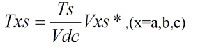
the different voltage is maintained. Teff is called the “effective time”. For the purpose of explanation, an imaginary time value will be introduced as follows
Vas *,Vbs*and Vcs* are the A-phase, B -phase, and C-phase reference voltages, respectively. This switching time could be negative in the case where negative phase voltage is commanded. Therefore, this time is called the “imaginary switching time”.
Now, the effective time can be defined as the time duration between the minimum and the maximum value of three imaginary times, as given by
Teff =Tmax-T min
Where Tmin = min(Tas,Tbs,Tcs) Tmax = max (Tas,Tbs,Tcs)
When the actual gating signals for power devices are generated in the PWM algorithm, there is one degree of freedom by which the effective time can be relocated
anywhere within the sampling interval.
Tga =Tas+Toffset Tgb =Tbs+Toffset Tgc =Tcs+Toffset
Where Toffset is the ‘offset time’
This gating time determination task is only performed for the sampling interval in which all of the switching states of each arm go to 0 from 1. This interval is called the “OFF sequence”. In the other sequence, it is called the “ON sequence.” In order to generate a symmetrical switching pulse pattern within two sampling intervals, the actual switching time will be replaced by the subtraction value, with sampling time as follows:
Tga =Ts-T ga Tgb =Ts -T gb Tgc =Ts-T gc
Mathematical model of PMSM
A surface-mounted synchronous machine is used in this
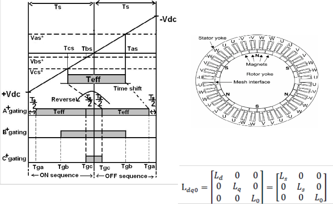
project, so the mathematical model of the PMSM is presented for this kind of machine.
Figure 2.1 show a cross section of the rotor and stator of a
PMSM.
Fig 4. Stator and rotor configuration of PMSM
Where the inductance matrix is expressed:
Fig.3 Actual gating time generation for continuous SVM
Therefore, a time-shifting operation will be applied to the imaginary switching times to generate the actual gating times (Tga ,T gb ,T gc ) for each inverter arm, as shown in Fig. 4. This task is accomplished by adding the
same value to the imaginary times as follows:
For SMPM, the d and q components of the inductances are the same. The notation dq is change for s, which refers to the stator. The magnetizing flux has the following expression:
IJSER © 2013 http://www.ijser.org
International Journal of Scientific & Engineering Research, Volume 4, Issue 12, December-2013 321
ISSN 2229-5518
A usual way to write the equation is in its expanded form. As far as the stator windings are wye-connected (with a neutral point) and supplied with balanced three phase currents, the zero-axis components are neglected [2]. The
Discrete,

s = 5e -005 s po we rgui
Va A A Vb B B
Vc C C
Step

Tm
A
m 
B
C
voltage equations for d and q axes are:
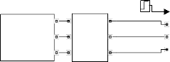
Fi ve Level CBSVPWM Inverter
LC Fi l ter
Permanent Magnet

Synchronous Machi ne
t
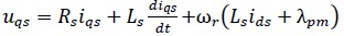
Where Rs is the stator resistance, Ls the stator inductance, ωr the rotor rotational speed and λpm the permanent magnet flux.
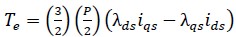
The electromagnetic torque of the machine can be expressed, in the dq reference frame, as follows:
Fig.5.Simulink model for three phase five level inverter fed PMSM
2500
2000
1500
1000
500
IJSER
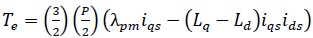
If the equation (2.2) is substituted in the torque equation, it
is obtained:
0
-500
0 0.1 0.2 0.3 0.4 0.5 0.6 0.7 0.8 0.9 1
Time
Fig.6.Output Speed of a five level inverter
Considering a non-salient rotor, where the inductances are equal, the final expression of the electromagnetic torque is:
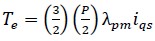
This result is quite interesting. It shows that the only component involved in torque production in a PMSM without saliency is the stator q-axis current.
SIMULATION RESULTS:
Permanent magnet synchronous motors (PMSMs) have been playing an important role in high performance drive systems.
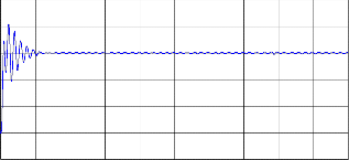
40
30
20
10
0
-10
-20
0 0.1 0.2 0.3 0.4 0.5 0.6 0.7 0.8 0.9 1
Time
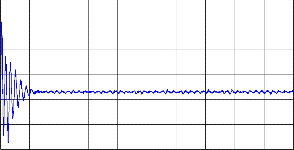
Fig.7.Output Torque of a five level inverter
500
400
300
200
100
0
-100
0 0.02 0.04 0.06 0.08 0.1 0.12 0.14 0.16 0.18 0.2
Time
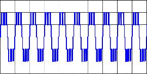
Fig.8.Output phase Voltage of a five level inverter
IJSER © 2013 http://www.ijser.org
International Journal of Scientific & Engineering Research, Volume 4, Issue 12, December-2013 322
ISSN 2229-5518
500
0
-500
0
2.5
2
1.5
1
Time
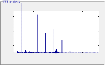
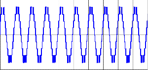
Fig.9.Output Line Voltage of a five level inverter
Fundamental (50Hz) = 24.86 , THD= 3.51%
synchronous motor in motion control application”.
[2 ] Deng, F., 1999. An Improved Iron Loss Estimation for permanent Magnet Brushless Machines. IEEE Transactions on Energy Conversion. Vol. 14, No. 4, pp. 1391-1395.
[3 ] Downing, S., Reunanen, A., Saari, J. and Arkkio, A. 2005. Losses, Cooling and Thermal Analysis of Electrical Machines, Lecture notes
of the postgraduate seminar, Espoo, Otamedia Oy, ISBN 951-22- 7991-6
[4 ] Engelmann, R. H,. Middendorf, W. H, 1995. Handbook of Electric motors, New York: Marcel Dekker Inc, 801.
[5 ] Gieras, J.F. and Wing, M., 1997. Permanent Magnet Motor
Technology –Design and Applications. New York: Marcel Dekker
Inc, p. 444.
[6 ] Heikkilä, T., 2002. Permanent Magnet Synchronous Motor for
Industrial Applications – Analysis and Design. Dissertation, Acta Universitatis Lappeenrantaensis 134, ISBN 951-764-699-2, 109 p. [7 ] Hendershot Jr, JR., Miller, T.J.E., 1994. Design of Brushless Permanent-Magnet Motors. Magna Physichs Publishing and Clarendon Press, Oxford, ISBN 1-881855-03-1. 574 p
0.5
IJSER
0
0 200 400 600 800 1000
Frequency (Hz)
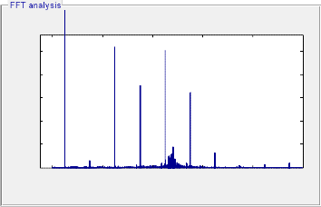
Fig.10. Determination of THD of line current of five level inverter fed
Fundamental (50Hz) = 343 , THD= 8.70%
5
4
3
2
1
0
0 200 400 600 800 1000
Frequency (Hz)
Fig.11. Determination of THD of line voltage of five level inverter
CONCLUSIONS:
In this paper, simulation analyses concerning the applications of CBSVPWM control strategy on the five level inverters fed Permanent Magnet Synchronous Motor are presented. From this analysis we can conclude that multilevel inverter can eliminate the harmonics produced by the normal inverter. From the simulation results
IJSER © 2013 http://www.ijser.org