International Journal of Scientific & Engineering Research, Volume 4, Issue 4, April-2013 643
ISSN 2229-5518
Moving object tracking based on position vectors
V.Purandhar Reddy, Y.B.Dawood, K.M.Yaagna Theja, C.Munesh, M.V.L.Sraavani, K.Thirumala Reddy
Abstract— In this paper, a novel algorithm for moving object tracking based on position vectors has proposed. The position vector of an object in first frame of a video has been extracted based on selection of ROI. Region of Interest (ROI) is a cropped image in a first frame. In this algorithm, object motion has shown in nine different directions based on the position vector in the first frame. We extract nine position vectors for nine different directions. With these position vectors second frame is cropped into nine blocks. We exploit block matching of the first frame with nine blocks of the next frame in a simple feature space. The matched block is considered as tracked block and its position vector is a reference location for the next successive frame. We describe algorithm in detail to perform simulation
experiments of object tracking which verifies the tracking algorithm efficiency.
1 INTRODUCTION
—————————— ——————————
he moving object tracking in video pictures has attracted a great deal of interest in computer vision. For object recogni-
tion, navigation systems and surveillance systems, object tracking is an indispensable first-step.
The conventional approach to object track- ing is based on the difference between the current image and the background image. However, algorithms based on the dif- ference image cannot simultaneously detect still objects. Fur- thermore, they cannot be applied to the case of a moving cam- era. Algorithms including the camera motion information have been proposed previously, but, they still contain problems in separating the information from the background.
In this paper, we propose block matching based Method for object tracking in video pictures. Our algo- rithm is based on position vector calculation and block match- ing .The proposed method for tracking uses block matching between successive frames. As a consequence, the algorithm can simultaneously track multiple moving and still objects in video pictures.
This paper is organized as follows. The proposed method consisting of stages position vector calcula- tion, feature extraction, block matching and minimum distance measure which are described in detail.
2 PROPOSED CONCEPT FOR MOVING OBJECT
TRACKING
2.1 Position vector calculation
2.1.1 position vector calculation for first frame
In general, image segmentation and object extraction meth- ods are used to calculate position vectors. In the proposed concept, first select the portion of an object which is to be tracked. The portion of an image is cropped in the first frame which is referred as block ie shown in the figure below
Y.B.Dawood, K.M.Yaagna theja, C.Munesh, M.V.L.Sraavani, are cur- rently pursuing bachelor degree program in Electronics and Communica- tion Engineerig in S.V.College of Engineering ,Tirupati,India .
PH-09490049532. E-mail:yaagnatheja@gmail.com
V.Purandhar Reddy is currently an Associate Professor in Electronics
and Communication Engineering in .S.V.College of Engineering, Tirupa- ti,India, PH-0994993345, E-mail-vpreddy4@gmail.com
K.Thirumala Reddy is currently an Asst Professor in Electronics and
Communication Engineering in .S.V.College of Engineering, Tirupa-
ti,India
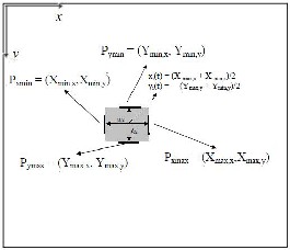
Fig.1: Explanation of the position vector calculation from the cropped image result
Based on co-ordinate parameters of an object, we extract the position of the pixel Pxmax (Pxmin) which has the maximum (minimum) x-component
Pxmax = (Xmax,x,Xmax,y), Pxmin = (Xmin,x,Xmin,y),
Where Xmax,x, Xmax,y, Xmin,x, and Xmin,y are x and y coordinates of the
Rightmost and leftmost boundary of the object i, respective- ly. In addition, we also extract
Pymax = (Ymax,x, Ymax,y), Pymin = (Ymin,x, Ymin,y).
Then we calculate the width w and the height h of the ob- jects as follows
wi(t) = Xmax,x − Xmin,x,
hi(t) = Ymax,y − Ymin,y.
We define the positions of each object in the frame as fol- lows
P = (X1,Y1)
IJSER © 2013 http://www.ijser.org
International Journal of Scientific & Engineering Research, Volume 4, Issue 4, April-2013 644
ISSN 2229-5518
X1(t) = (X max,x + X min,x)/2
Y1(t) = (Ymax,y + Ymin,y)/2
2.1.2. Position Vectors in nine different directions
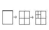
Frame to Frame movement distance of an object is negligible. So, we consider movement shift by “m” units in nine differ- ent directions as shown in the below figure.
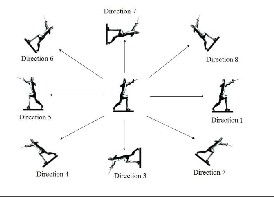
Fig.2: Position of object in nine different directions
For Direction 1, position vector shift P1= (X1-m,Y1) For Direction 2, position vector shift P2= (X1+m,Y1) For Direction 3, position vector shift P3= (X1,Y1+m) For Direction 4, position vector shift P4= (X1,Y1-m) For Direction 5, position vector shift P5= (X1-m,Y1-m)
For Direction 6, position vector shift P6= (X1+m,Y1+m) For Direction 7, position vector shift P7= (X1-m,Y1+m) For Direction 8, position vector shift P8= (X1+m,Y1-m) For Direction 9, position vector shift P9= (X1,Y1)
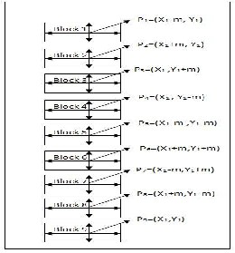
Based on the position vectors P1,P2,P3,P4,P5,P6,P7,P8 and P9 crop the second frame into nine blocks as shown in figure.3.
.
Fig.3: Block Extraction using Nine Position Vectors
2.2 FEATURE EXTRACTION FOR BLOCKS
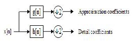
2.2.1 DISCRETE WAVELET TRANSFORM
2D-Discrete Wavelet Transform
A weakness shared by most of the texture analysis schemes is
that the image is analyzed at one single-scale. A limitation that
can be lifted by employing multi-scale representation of the
textures such as the one offered by the wavelet transform.
Wavelets have been shown to be useful for texture analysis in
literature, possibly due to their finite duration, which provides
both frequency and spatial locality. The hierarchical wavelet
transform uses a family of wavelet functions is associated scal-
ing functions to decompose the original signal/image into
different sub bands. The decomposition process is recursively
applied to the sub bands to generate the next level of the hier- archy.
.
This shows one level DWT. At every iteration of the DWT, the
lines of the input image (obtained at the end of the previous
iteration) are low-pass filtered and high pass filtered. Then the lines of the two images obtained at the output of the two fil- ters are decimated with a factor of 2.
Next, the columns of the two images obtained are low and high pass filtered. The columns of those four images are also decimated with a factor of 2. Four new sub-images represent- ing the result of the current iteration are generated. The first one, obtained after two low-pass filtering, is named approxi- mation sub-image (or LL image). The others three are named as detail sub-images: LH, HL and HH. The LL image repre- sents the input for the next iteration.
In this paper we have used level 2 Haar transform. Only the second level LL image is used for the analysis as that contains most of the important information for feature vector calcula- tion. For first frame the feature vector is f1 based on cropped image using position vector P1.For next frame feature vector set is V={V1,V2,V3,V4,V5,V6,V7,V8,V9} based on position vec- tors P1,P2,P3,P4,P5,P6,P7,P8 &P9.
IJSER © 2013 http://www.ijser.org
International Journal of Scientific & Engineering Research, Volume 4, Issue 4, April-2013 645
ISSN 2229-5518
2.3 Block Matching and Distance Measure
Proposed algorithm for object tracking exploit block matching with the DWT features above and make use of min- imum distance search in the feature space. We now go into moré details of our algorithm.
Using the cropped images result of the object in the tth frame, we first extract the DWT coefficients of the cropped image (N+1,i). Here the notation N+1,i stands for the cropped image in the tth frame. Then we perform the minimum dis- tance search between (N+1,i) and (N,j) for all cropped images j in the next frame using position vectors. Finally the cropped image N+1,i is identified with the cropped image in the next frame which has minimum distance from N+1,i. Repeating this matching procedure for all the frames with first frame, we can identify all blocks one by one and can keep track of the blocks between frames.
Further refinements of the proposed algorithm are as follows: We have not specified the distance measure used for matching yet. In the simulation experiments we could confirm that be- sides the Euclidean distance DE the simpler Manhattan dis- tance DM is already sufficient for object tracking purposes. Figure 4 shows a Distance measure between feature vectors. Figure 5 shows a Block diagram of the proposed object track- ing algorithm.
Fig.4: Distance measure between feature vectors.
2.3.1 OBJECT TRACKING ALGORITHM
1. Input video
2. Crop the first frame for ROI(Region Of Interest)
3. Calculate position vector for cropped portion.
P=(X1,Y1)
4. Based on position vector calculate nine position vec-
tors with X and Y co-ordinate shift by ‘m’ units.
P1= (X1-m,Y1), P2= (X1+m,Y1), P3=(X1,Y1+m),P4=(X1,Y1-m), P5= (X1-m,Y1-m),P6= (X1+m,Y1+m), P7= (X1-m,Y1+m), P8= (X1+m,Y1- m), P9= (X1,Y1)
5. For previous frame i.e first frame perform DWT for
cropped block to get feature vector f1.
6. Similarly perform DWT for all cropped blocks in the
next frame N+1 to get the feature vectors V1 ,V2, V3,
V4, V5, V6, V7 ,V8, V9 .
V= { V1, V2, V3, V4, V5, V6, V7, V8, V9}
7. Block matching distance measure
a.) Calculate the distance measured using Manhat- tan distance between f1 and V.
We get distance set of D = {D1, D2, D3, D4, D5, D6, D7, D8, D9}
where D1= Distance between f1 and V1 similarly for D2,D3,D4,D5,D6,D7,D8 and D9 are calculated.
b.) Apply block matching of Nth frame cropped im-
age with minimum distance block of N+1th frame.
If not matched, perform for next successive
frame.
c.) After matching remove the position vector data
of Nth frame and store the data of position vector
of N+1th frame.
d.) Increase the value of N by N+1.
8. Repeat the steps from 1 to 7.
Fig.5: Block diagram of proposed object tracking method
IJSER © 2013 http://www.ijser.org
International Journal of Scientific & Engineering Research, Volume 4, Issue 4, April-2013 646
ISSN 2229-5518
3 SIMULATION RESULTS
The proposed algorithm is tested by using Matlab 7.1. For experimental verifications two different video sequences were taken from moving camera, then frames were extracted from the video sequences. Since, all the processing has done on col- our images, 24 bit color image first frame has been initially taken as reference frame to calculate position vector. By giving frames one after the other to the Matlab program of proposed algorithm, the tracked object location is extracted.
5 REFERENCES
[1] Object Tracking based on pattern matching V. Pu- randhar Reddy, International Journal of Advanced Re- search in “ Computer Science and Software Engineering “, Volume 2, Issue 2, February 2012.
[2] Object Tracking based on Image Segmentation and pattern matching V. Purandhar Reddy, International Journal of Computer Science and Information technology, Issue 2, May 2012.
[3] Object Tracking based on Image Segmentation and pattern matching, V. Purandhar Reddy, GJCEA issue-1, Feb


2012.


Fig.6: The tracked object results from successive frames
4 CONCLUSION
We have proposed an object tracking algorithm for video pic- tures, based on position vectors and block matching of the extracted objects between frames in a simple feature space. Simulation results for frame sequences with moving objects verify the suitability of the algorithm for reliable moving ob- ject tracking. We also have confirmed that the algorithm works very well for more complicated video pictures includ- ing rotating objects and occlusion of objects. It is obvious that, the simulation result in the proposed algorithm is quite enough to apply for the real time applications. We would like to implement this algorithm with feature vectors in different vectors for future applications too.
[4] H. Kimura and T. Shibata, “Simple-architecture mo- tion-detection analog V-chip based on quasi-two-dimensional processing,” Ext. Abs. of the 2002 Int. Conf. on Solid State De- vices and Materials (SSDM2002), pp. 240– 241, 2002.
[5] John Eakins and Margaret Graham. Content-based image retrieval. Project Report University of Northumbria at Newcastle.

[6] Datta et.al. 2005. Content-based image retrieval ap- proaches and trends of the new age. In Proceedings of the 7th ACM SIGMM International Workshop on Multimedia infor- mation Retrieval. Singapore: ACM Press. pp.253-262.
[7] Datta et. al. 2008. Image retrieval: idea influences,
and trends of the new age. ACM Computing Sur- veys.vol.40(2), pp.1-60.
[8] Swain et. al. 1991. Color indexing. International
Journal of Computer Vision.vol.7(1), pp.11–32.
[9] Stricker et. al. 1995. Similarity of color image. In Proceedings of SPIE on storage retrieval for image and video databases, California.Vol. 2420, pp. 381-392.
[10] Gao Li-chun and Xu Ye-qiang. 2011. Image retrieval based on relevance feedback using blocks weighted dominant colors in MPEG-7. Journal of Computer Applications.vol.31(6), pp.15491551.
[11] H B Kekre and V A Bharadi. Modified BTC & walsh
coefficients based features for content based image retrieval. NCICT, India.
[12] S.Vidivelli and S.Sathiya devi. 2011. Wavelet based integrated color image retrieval. IEEE-International Confer- ence on Recent Trends in Information Technology, ICRTIT.
[13] Kekre et. al. 2010 IEEE. Content based image re- treival using fusion of gabor magnitude and modified block truncation coding. Third International Conference on Emerg- ing Trends in Engineering and Technology.
[14] Wang Xiangyang and Hu Fengli. 2007. A robust
color image retrieval based on significant bit-plane. Journal of
Image and Graphics.vol.12(9) , pp.1647-1652.
IJSER © 2013 http://www.ijser.org