International Journal of Scientific & Engineering Research Volume 3, Issue 6 , June-2012 1
ISSN 2229-5518
Rinku Roy, Amit Konar, Prof. D. N. Tibarewala, R. Janarthanan
Abstract—Some diseases or spinal cord injury completely destruct the sensory, motor and autonomous function for the limb movement. BCI (Brain computer Interface) provides a new communication pathway for those patients. Imagination of limb movements is used to operate a BCI. With analysis of acquired EEG signal due to motor imagery controlling of an artificial limb is possible. For t his technique motor imagery EEG signal is classified and the classified part is fed to a controller to execute exactly that movement. State feedback PI controller can be used to control an artificial limb. With help of this controller not only position but also vel ocity can be controlled. In this paper, a simulated model of EEG driven artificial limb control using state feedback PI controller is pres ented. For this study, EEG data for motor imagery was taken from five healthy subjects. The wavelet coefficients are calculated from that EEG signals as features and the obtained features are classified by SVM classifier to determine the part of the limb the user wants to mo ve. The initial and target position are fed to the controller and the controller move the artifici al limb to reach the target position at the classified direction. The overall control procedure is done using Matlab 7.6.
Index Terms— Brain-computer interface (BCI), Electroencephalogram (EEG), Event Related Synchronization (ERS), Event Related De-synchronization (ERD), wavelet coefficients, Support Vector Machine (SVM) classifier, State feedback
& PI controller..
—————————— ——————————
I. INTRODUCTION
Brain computer interfacing (BCI) systems have created a new direct channel of communication between the brain & computers [1, 2]. In BCI system, machines are operated just by thinking. BCI use brain signals to convert user‘s intentions into computer commands. It is potentially the ultimate device to help people with motor disability specially those suffering from conditions whereby motor pathways are intact but conventional conscious control over them has been interrupted, such as Amyotrophic Lateral Sclerosis (ALS) or locked in state [3]. For BCI technique,
brain measurements are necessary. There are different techniques are available for brain measurements, some are invasive (e.g., ECoG) and some are non-invasive (e.g., EEG, MEG). Among several non-invasive techniques EEG is mostly used because it is portable & cost-effective.
Human somatotopic organization indicates that human limbs are controlled by contra-lateral brain hemispheres. Many neuro-physiological and neuro-imaging studies have confirmed the nature of contra-lateral control [4]. Human has intention to move, and human movement intention is associated with at least two kinds of brain activity that can be observed in EEG; Event Related Potential (ERP) [5, 6] and alpha (8-13Hz) and beta band (16-30Hz) event-related de-synchronization (ERD) [5, 7] i.e. oscillation amplitude decrease.
Functional study found that the corresponding motor areas are activated when human intends to move before the actual production of certain limb movement [8, 9]. Therefore, we may discriminate human movement intentions before actual movement from spatial distribution of brain activities. During physical and motor imagery of right- and left-hand movements, beta band brain activation (15-30 Hz) ERD occurs predominantly over the contra-lateral left and right motor areas. The brain activity associated with ceasing to move, the post-movement ERS i.e. oscillation amplitude increase can also be found over the contralateral motor areas.
A conceptual schema on the control system of neuro- prosthesis using EEG measurement signal is proposed [10]. The system indicated that there is a relation between human hand movements and the EEG signals. The rapid prototyping of an EEG-based Brain-computer Interface (BCI), which could discern the imagined task, either left or right hand movement using an adaptive autoregressive model and linear discrimination analysis was presented [11]. An approach on optimal spatial filtering of a single trial EEG during an imagined hand movement was presented [12]. It was discussed that EEG signals and an enhanced resource-allocating neural network could be used to detect the voluntary hand movements [13].
To move a prosthetic arm by the extracted signals from EEG for motor-imagery, it is necessary to decode the various movement based informations through suitable classification of the ERD for the generation of control signals for the execution of same movements.
————————————————
![]() Author Rinku Roy is currently pursuing masters degree program in Bio-Medical engineering in Jadavpur University,India,
Author Rinku Roy is currently pursuing masters degree program in Bio-Medical engineering in Jadavpur University,India,
E-mail: rinku.roy87@gmail.com
![]() Co-Author Amit Konar is a faculty of Electronics and Tele-communication
Co-Author Amit Konar is a faculty of Electronics and Tele-communication
Engg.Department in Jadavpur University, India, E-mail: konaramit@yahoo.co.in
![]() Co-Author D. N. Tibarewala is an ex- faculty of School of bioscience and
Co-Author D. N. Tibarewala is an ex- faculty of School of bioscience and
Engg.Department in Jadavpur University, India, E-mail: biomed.ju@gmail.com
![]() Co-Author R.Janarthanan is a faculty of IT.Department in Jaya Engg college,
Co-Author R.Janarthanan is a faculty of IT.Department in Jaya Engg college,
Chennai, India,
E-mail: srmjana_73@yahoo.com
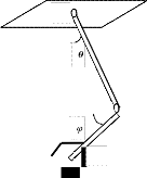
Thus, the kinematic arm movement forms the basis for any controller design. In our realization, we attempt to control the position of a gripper of a robot by automatically adjusting the angular position of two-links. The robot to be used has a structure like the one shown in Figure1.
In this paper, acquired EEG signal is classified from the motor imagery to know the part of the limb which patient wish to
IJSER © 2012 http://www.ijser.org
International Journal of Scientific & Engineering Research Volume 3, Issue 6 , June-2012 2
ISSN 2229-5518
move. In this paper, we classified movement of hindarm and forearm by SVM classifier. Results are obtained with 5 able- bodied participants. To reach the artificial hand in proper target we used a PI controller with steady state feedback. Current positions and velocities of two joints were used as four states in this controller. The controller moved artificial limb until it reached at target position. The whole controller model was designed using Matlab 7.6.
B
Figure 2: Electrode placement for recording EEG signal due to movement imagination. Electrodes are placed on the C3, C4 & CZ over the scalp
D
After acquiring EEG signals, these were pre-processed in order
C to reduce noise artefacts and/or enhance spectral components that contain important information for data analysis. This step
Figure 1 : In above figure, we need to control θ and φ to control the arm BD and DC respectively. The robotic links BD and DC can be analogously be compared with the hindarm and forearm of the participant. So when the forearm is thought to move by an angle φ and the hind arm by an angle ![]() , we want to move the robot arms CD and BD respectively.
, we want to move the robot arms CD and BD respectively.
II. METHOD
In order to set up the BCI in inexperienced BCI users to
operate an artificial arm with only one motor imagery pattern, a set of experiments and feedback paradigms was devised.
Five healthy subjects (3 males & 2 females) between the ages of
23 and 28 participated in this study. They were right handed according to the Edinburgh inventory. Prior to this study, none of these subjects had been exposed to a BCI system or were informed of the experimental hypothesis.
The subjects were sitting comfortably in an armchair, in front of
a computer screen. Before the experiment started, they were instructed about the task. one out of four different visual cues involved in shoulder joint & elbow joint movement was presented in a consecutive manner for both right and left arm.
improves the signal-to-noise ratio (SNR), so it is easy to further processing. From the acquired EEG signal alpha band (8-12 Hz)
& beta band (12-30 Hz) were extracted. From these two frequency bands we can get the maximum movement related information. These two frequency bands were extracted by band- pass filter of related frequency using signal processing toolbox of
MATLAB. After that ERD is computed from Event related EEG trials by doing Hilbert Transform [14] of the band pass filtered event-related EEG signal.
The Hilbert transform of a given signal s (t) is defined as,
h (t) = ![]() dτ
dτ
=![]()
A wavelet is a waveform of limited duration that has an
average value of zero. These wavelets are obtained from a single prototype wavelet called the mother wavelet by dilations, contractions and shifting, which is the fundamental approach of wavelet transformation [15], [16]. The property of wavelet transformation to discriminate both temporal and spatial domain parameters make it an inevitable tool for feature extraction from EEG signals. The continuous wavelet transform (CWT) treats a function of time in constituent oscillations, localized in both time and frequency [17]. The CWT defined as follows:
Six sintered Ag/AgCl electrodes were mounted over![]()
γ (s,τ) = *
(t) dt
sensorimotor areas covering C3, C4 and CZ with the reference at the left and right ear lobe. The EEG was recorded using a neurowin, NASAN India device with a 0.01- 35 Hz bandpass filter, notch filter on (50 Hz), sampling frequency 250 Hz and a sensitivity of 100µV.![]()
![]()
![]()
Ψ s,τ (t) = Ψ ( )
where * denotes complex conjugation, τ is referred to as the translation, giving the position in time, and s the scale parameter, which is inversely related to the frequency content. Ψ (τ) called the mother wavelet, and in this study standard Daubechies
IJSER © 2012 http://www.ijser.org
International Journal of Scientific & Engineering Research Volume 3, Issue 6 , June-2012 3
ISSN 2229-5518
function is used. The discrete wavelet transform (DWT) in turn, is the result of selecting scales and translations based on powers of two, yielding a more efficient yet as accurate analysis.
In order to limit the analysis to a smaller number of discriminative signal features, the DWT was applied to the filtered values of the data set, and the coefficients were established. The processing was performed using the wavelet toolbox in Matlab 7.6.
Extracted features were fed into classifier to identify patterns of
brain activity (i.e., subject intended to move either hindarm or forearm). In this study classification was done by Support Vector Machine (SVM) [18, 19] classifier. In here, we classified Resting-Non Resting motor imagery data, Left-Right hand movement related motor imagery data and Hindarm-Forearm movement related motor imagery data from EEG.
At first we consider equations of motion of robot manipulator
links. The behaviour of a rigid-link artificial arm is governed by the following second-order differential equation [18]:![]()
![]()
ij ![]() i + Ki + Gi = i i = 1, . . . . . ., n (1) Where,
i + Ki + Gi = i i = 1, . . . . . ., n (1) Where,
![]()
![]()
, ![]() are the position, velocity, and acceleration of joint i ; i is the torque( or force) acting at joint i ; Mij is the coupling inertia ; Ki is the coefficient of Centripetal and Coriolis forces; Gi is the gravity force. For i = 1, 2, the equation (1) become,
are the position, velocity, and acceleration of joint i ; i is the torque( or force) acting at joint i ; Mij is the coupling inertia ; Ki is the coefficient of Centripetal and Coriolis forces; Gi is the gravity force. For i = 1, 2, the equation (1) become,![]()
![]()
![]()
![]()
![]()
![]()
M11 1+M12 2+K1 (![]() 2, 1, 2)+G1(
2, 1, 2)+G1(![]() 1,
1,![]() 2)= 1 (2) M21 1+M22 2+K2 (
2)= 1 (2) M21 1+M22 2+K2 (![]() 2, 1, 2)+G2(
2, 1, 2)+G2(![]() 1,
1,![]() 2)= 2 (3)
2)= 2 (3)
deriving control laws and provide a model for computer simulations. Because of the complexity and non-linearity of these equations, it is difficult to directly design control laws.
Instead, we shall linearize the control equations using a nonlinear feedback and a state space transformation. The linearization process brings a nonlinear control problem into a linear control problem.
We first express the control equations (2) and (3) in state space.
To do so, let
So, finally the state equations are:
(7)![]()
(8)
(9)
(10)
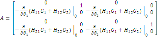
(7), (8), (9) and (10) represent nonlinear system with state x, input τ, and output y. To simplify control design, we would like to linearize the system. In order to linearize this model, it is first noted that the coriolis and centrifugal forces are all quadratic in the angular velocity, so that for any linearization around a stationary point, i.e., one with ![]() =
= ![]() = 0, these terms disappear. After applying the state space transformation, the original nonlinear system (7), (8), (9) and (10), are converted into a decoupled linear system in the Brunovsky canonical form
= 0, these terms disappear. After applying the state space transformation, the original nonlinear system (7), (8), (9) and (10), are converted into a decoupled linear system in the Brunovsky canonical form![]()
(11a) (11b)
Where,![]()
From equation (4) we get,

(4)
By putting the above value of ![]() 1
1![]() in the equation (3), we get ;
in the equation (3), we get ;
![]() 2 = - H21 (K1+G1) – H22 (K2+G2) + H21τ1 + H22τ2 (5)
2 = - H21 (K1+G1) – H22 (K2+G2) + H21τ1 + H22τ2 (5)
where,![]() And
And ![]()
Similarly, we calculate the value of ![]() 2
2![]() from the
from the
equation(3) and put the value in equation (4). So, we get
![]() 1 = - H11 (K1+G1) – H12 (K2+G2) + H11τ1 + H12τ2 (6) Where,
1 = - H11 (K1+G1) – H12 (K2+G2) + H11τ1 + H12τ2 (6) Where,
![]() And
And ![]()
In the previous section, we established control equations
of a manipulator. These equations are suitable for
The system of equation (11) is composed of n identical subsystems. The control design problem of artificial arms is simplified as a design problem of each subsystem. The subsystems are, however, unstable since each subsystem has some repeated poles at the origin. But the subsystems are controllable and, therefore, we can place poles arbitrarily by a constant feedback. In this study, the controller was designed and simulated using Matlab7.6.
III. RESULTS
The EEG data were taken by using Neurowin device, placing proper electrodes on the scalp. The raw EEG data are then filtered using Signal processing toolbox of Matlab7.6. After that
IJSER © 2012 http://www.ijser.org
International Journal of Scientific & Engineering Research Volume 3, Issue 6 , June-2012 4
ISSN 2229-5518
wavelet coefficients are extracted from the processed signal for Classification. The result of signal processing and feature extraction is shown in following figure:
Bandpass filtered data(12-30 Hz)
50
0 ![]()
-50
0 100 200 300 400 500 600 700 800 900 1000
Approximation coefficients
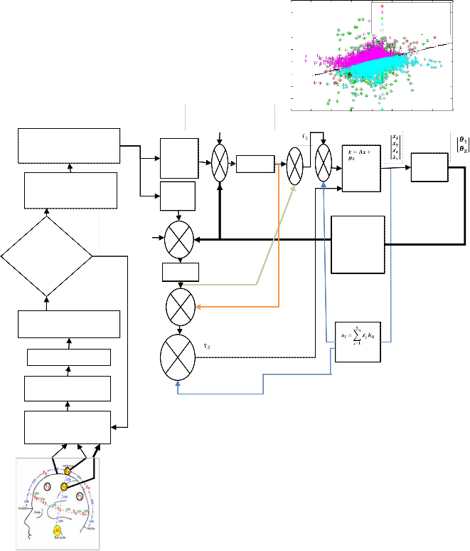
Figure 4: The block diagram of the overall method. In this model, Ui = Output of the PI cont
Kij = State feedback gain; ![]() = States of c
= States of c
After that extracted features were first fed into a SVM classifier to know whether the subject wants to move his hand on not (resting or non-resting). The result of SVM classifier is shown in following figure:![]()
![]()
40
20
0
0 50 100 150 200 250 300 350 400 450 500
Detail coefficients
1
0
SVM classifier
10
8
6
4
2
NON-RESTING (training) NON-RESTING (classified) REST (training)
REST (classified)
Support Vectors
-1
0 50 100 150 200 250 300 350 400 450 500 0
Figure 3 : Results of pre-processing and feature extraction from the raw
EEG signal
. Desired angular position
Shoulder joint
Classification of hindarm-
-2
-4
-6
-8
-4 -3 -2 -1 0 1 2 3 4
Figure 5: fication result of restin esting motor imagery data by SVM
cla
forearm movement related
motor imagery data
Classification of left –Right hand movement related motor imagery data
Rotate
Shoulder joint motor
Rotate Elbow joint motor
U1
PI + +
_ Controller + _
Y= Cx
Does the subject want to move his arm?
Desired angular
position of +
Elbow joint -
PI
Move classified part of the arm at desired angle
Controller
+
+
Classification of resting –
non resting imagery data U2
+ Feature Extraction
_
Band Pass filtered (8-
12 Hz)
Acquired raw EEG data due to motor imagery
IJSER © 2012 http://www.ijser.org
International Journal of Scientific & Engineering Research Volume 3, Issue 6 , June-2012 5
ISSN 2229-5518
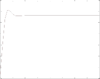
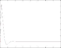
controller. Here, we used state feedback PI controller. By this controller we can control not only angular position but also angular velocities. The initial angular velocities for both joints were zero. Velocities and angular position of two joints fed as four states in state feedback PI controller. The initial angular position for the shoulder joint and elbow joint were 0.7850radian and -0.5233radian respectively. The desired angular position for the shoulder joint and elbow joint were -0.7850radian and
0.5233radian respectively. The controller responses were shown in following figures.
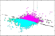
If the data belonged to ‗resting‘ class, then EEG data were again
acquired from the subject for the next second. If the data was in
‗non-resting‘ class, i,e subject wants to move his hand; data were fed into second classifier to know which hand (left or right) subject wants to move. We classified left and right hand movement related motor imagery data by SVM classifier. The result of the SVM classifier is shown in following figure: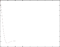
0.8
0.6
0.4
0.2
0
-0.2
-0.4
-0.6
SVM classifier
8
6
4
RIGHT (training) RIGHT (classified) LEFT (training) LEFT (classified) Support Vectors
-0.8
-1
0 0.5 1 1.5 2 2.5 3 3.5 4 t sec
Figure 4 : Controller response for the shoulder joint rotation
2
0
-2
-4
-6
-4 -3 -2 -1 0 1 2 3 4
Figure 6: Classification result of right-left hand movement related motor imagery data by SVM classifier
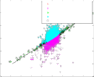
The left and right hand motor imagery data were again fed to another classifier which classify hindarm and forearm movement for the classified arm (Left or Right). For this classification we again used SVM classifier. The result of this classification is
0.8
0.6
0.4
0.2
0
-0.2
-0.4
-0.6
0 0.5 1 1.5 2 2.5 3 3.5 4 t sec
shown in following figure:
Figure 5 : Controller response for the elbow joint rotation
SVM classifier
6

Hindarm movement (training) 1
Hindarm movement (classified)
4 Forearm movement (training) 0
Forearm movement (classified)
Support Vectors
-1
2
-2
0
-3
-2 -4
-5
-4
-6
-6
-5 -4 -3 -2 -1 0 1 2 3 4
-7
0 0.5 1 1.5 2 2.5 3 3.5 4
t sec
Figure 7: Classification result of hindarm-forearm movement related motor
imagery data by SVM classifier
After hindarm and forearm movement classification from motor imagery data, the classified result fed into the controller as binary input. The desired and the initial angular position for both the shoulder and the elbow joint were also fed as the input to the
Figure 6 : Controller response for the angular velocity of shoulder joint
IJSER © 2012 http://www.ijser.org
International Journal of Scientific & Engineering Research Volume 3, Issue 6 , June-2012 6
ISSN 2229-5518
7
6
5
4
3
2
1
0
-1
0 0.5 1 1.5 2 2.5 3 3.5 4
t sec
Figure 7 : Controller response for the angular velocity of elbow joint
The controller moved the artificial limb from the initial position to the desired position. The result of the movement of the artificial limb is shown in following figure.
In this study we moved a graphical artificial limb by the controller inputs.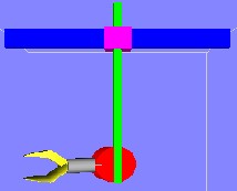
Figure 8 : Initial position of the artificial limb
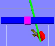
Figure 9 : final position of the artificial limb
IV. CONCLUSION
The objective of this paper is to represent an idea of controlling an artificial limb based on BCI to provide disabled users independence from care givers. This allows a person to communicate with or control the external world without using
the brain‘s normal output pathways of peripheral nerves and will enable patients to carry out basic daily tasks more easily. Here, we used only wavelet coefficients as feature. But, we can use other features like AR (Auto Regressive) parameter, PSD (Power spectral Density), amplitude value of the signal. By LDA (Linear Discriminant Analysis), QDA (Quadratic Discriminant Analysis), KNN (K nearest Neighbour) we can also classify motor imagery data. Here, we use only SVM (Support Vector Machine) classifier because its classification accuracy is higher than other classifier. We used State feedback controller to control the artificial limb. Angular position of the two joint fed as the input of the controller. Positions and velocities of two joints were the four states by which the controller worked and reached at the target positions.
V. REFERENCES
1. Wolpaw, J.R., Birbaumer, N., McFarland, D.J., Pfurtscheller, G., and Vaughan, T. M. (2002). Brain-computer interfaces for communication and control. Clin. Neurophysiol. 113, 767-791.
2. J. J. Vidal, ―Toward direct brain-computer communication,‖ Annu. Rev.
Biophys. Bioeng., vol. 2, pp. 157-180, 1973.
3. Birbaumer N, Murguialday A R and Cohen L 2008 Brain–computer interface in paralysis Curr. Opin. Neurol. 21 634–8
4. Bai O, Mari Z, Vorbach S and Hallett M 2005 Asymmetric spatiotemporal patterns of event-related desynchronization preceding voluntary sequential finger movements: a high-resolution EEG study Clin. Neurophysiol. 116
1213–21.
5. R.A.G. Vogels. Event-related synchronization in neurometric EEG data- - A study in children with ADHD-. Master of Science thesis. Project period: September 2004 - September 2005. Report Number: 32-05. Eindhoven University of Technology. Department of Electrical Engineering. Signal Processing Systems.
6. H. Shibasaki and M. Hallett, "What is the Bereitschaftspotential?,"Clin
Neurophysiol, vol. 117, pp. 2341-56, 2006.
7. A. Stancak, Jr. and G. Pfurtscheller, "Event-related desynchronisation of central beta-rhythms during brisk and slow self-paced finger movements of dominant and nondominant hand," Brain Res Cogn Brain Res, vol. 4, pp.
171-83, 1996.
8. O. Bai, Z. Mari, S. Vorbach, and M. Hallett, "Asymmetric spatiotemporal patterns of event-related desynchronization preceding voluntary sequential finger movements: a high-resolution EEG study," Clin Neurophysiol, vol.
116, pp. 1213-21, 2005.
9. C. Toro, G. Deuschl, R. Thatcher, S. Sato, C. Kufta, and M. Hallett, "Event- related desynchronization and movement-related cortical potentials on the ECoG and EEG," Electroencephalogr Clin Neurophysiol, vol. 93, pp. 380-9,
1994.
10. T. Richard, P. Lauer, P. Hunter, L. K. Kevin, and J. H. William,
―Applications of cortical signals to neuro-prosthetic control: A critical
review,‖ IEEE Trans. on Rehabilitation Engineering, vol. 8, no. 2, pp. 205-
208, June 2000.
IJSER © 2012 http://www.ijser.org
International Journal of Scientific & Engineering Research Volume 3, Issue 6 , June-2012 7
ISSN 2229-5518
11. G. Christoph, S. Alois, N. Christa, W. Dirk, S. Thomas, and P. Gert, ―Rapid prototyping of an EEG-based brain-computer interface (BCI),‖ IEEE Trans. on Neural Systems and Rehabilitation Engineering, vol. 9, no. 1, pp. 49-58, March 2001.
12. H. Ramoser, J. Muller-Gerking, and G. Pfurtscheller, ―Optimal spatial filtering of single trial EEG during imagined hand movement,‖ IEEE Trans. on Rehabilitation Engineering, vol. 8, no. 4, pp. 441-446, December 2000.
13. A. Erfanian and M. Gerivany, ―EEG signals can be used to detect the voluntary hand movements by using an enhanced resource-allocating neural network,‖ Proc. of the 23rd Annual International Conference of the IEEE Engineering in Medicine and Biology Society, vol. 1, pp. 721-724, October
2001.
14. R.A.G. Vogels. Event-related synchronization in neurometric EEG data- - A study in children with ADHD-. Master of Science thesis. Project period: September 2004 - September 2005. Report Number: 32-05. Eindhoven University of Technology. Department of Electrical Engineering. Signal Processing Systems.
15. Darvishi S., Al-Ani A. ―Brain-computer interface analysis using continuous wavelet transform and adaptive neuro-fuzzy classifier‖, Proceedings of the
29th International Annual Conference IEEE Engineering, Medicine and
Biology Society, August 2007, pp. 3220-3223.
16. Mallat S., ―A wavelet tour of signal processing: The Sparse way‖, 3rd ed., Elsevier, Academic Press.
17. Walnut DF: An introduction to wavelet analysis Boston, MA, USA: Birkhäuser; 2002.
18. F Lotte1, M Congedo, A Lecuyer, F Lamarche and B Arnaldi. ―A review of classification algorithms for EEG based Brain- computer Interface‖. Topical Review. published in "Journal of Neural Engineering 4 (2007)"
19. Guido Dornhege, Matthias Krauledat, Klaus-Robert Muller, and Benjamin Blankertz. General signal processing & Ma chine learning tools for BCI analysis.
20. Tzyh-Jong Tarn, Fellow, IEEE, Antal K. Bejczy, Fellow, IEEE, Xiaoping Yun, Member, IEEE, and Zuofeng Li, Member, IEEE, ―Effect of motor dynamics on nonlinear feedback robot arm control‖. IEEE transactions on
robotics and automation, vol 7, no.1, February 1991.
IJSER © 2012 http://www.ijser.org