has a ground plane on the other side as shown in Fig1.
Where
International Journal of Scientific & Engineering Research Volume 2, Issue 7, July-2011 1
ISSN 2229-5518
Modified Compact High Gain Multiple Patch Slotted Microstrip Antenna for Multiband Wireless Applications
A. Beno, Dr.D.S. Emmanuel, T. Sindhuja, K. Packia Lakshmi
Abstract— A modified approach for the design of a compact multi-element patch antenna which operates in pentaband is proposed. The antenna comprises of a main patch with subpatches containing resonating slots. The main patch is fed with a
50Ω microstrip line. The antenna operates with multiple operational frequencies covering the bands from 1.9GHz to 9.5GHz with good impedance matching. The design is verified using simulation software ANSOFT HFSS and tested using the laboratory experimental approach which resembles the simulated output with an omnidirectional radiation characteristics.The multipatch antenna achieved a Peak Gain of 14.47 dB at 8.38 GHz and stays above 2.42 dB through the entire operating band. The frequency of operation is suitable for wireless devices supporting multiple standards including Universal Mobile telecommunication System (UMTS, 1920-2170 MHz), Wireless Local Area Network (WLAN, 2400-2483.5 MHz) and low band Worldwide Interoperability for Microwave Access (WIMAX, 2.5 to 2.8 GHz).
Index Terms— ANSOFT HFSS, Compact, High Gain Microstrip feed, Multi-element Patch, Omni directional, Slotted Patch, Wireless Applications.
—————————— ——————————
N today’s modern communication industry, antennas are the most important components required to create a communication link. Microstrip patch antennas are increasingly used structure in various wireless applica- tions fields [1], because of their low profile, light weight and low power handling capacity [2]. They can be de- signed in a variety of shapes in order to obtain enhanced gain and bandwidth for multiband frequency application
independent of the operating frequency [3].
The concept of miniaturization is widely used in the
present technological developement arena to minimize
the effective electrical length of the antenna operatable at
lower frequencies. Several methodologies were adapted
to miniaturize a patch antenna [4]. Electromagnetic band-
gap (EBG) structure is used as defected ground plane structure to reduce size and achieve multiband resonant
frequencies [5]. To have multiple resonant frequencies one of the methods implemented is using slots on the ra- diating patch [6]. Many novel structures like Tapered Slot, Square Slot, U-Slot, T-Slot, V-Slot and many other shapes and structures were used by researchers reported in literatures [7], [8], [9]. The operating frequency charac- teristics obtained depend on the shape and position of the slots and also determine the ultra wideband characteris
————————————————
Dr.D.S. Emmanuel is with the School of Electronics Engg. Vellore Insti- tute of Technology, Vellore, India. E-mail: dsemmanuel@vit.ac.in
K. Packia Lakshmi has completed UG in ECE from Dr.SACOE
-tics of the antenna [10]. When the slot is generated on the radiating patch element the currents and the excited mode is perturbed which helps to reduce the effective designed resonant frequency towards achieving miniatu- rization.
Another technique to obtain the multiband frequency is meandering the patch. Meandering is achieved by in- serting several narrow slits at the patch elements non ra- diating edges. The excited patch radiating elements sur- face current is effectively meandered leading to a greatly lengthened current path for a fixed patch linear dimen- sion. This behavior results in a greatly lowered antenna fundamental resonant frequency and thus a large antenna size reduction at a fixed operating frequency is achieved [11]. The microstrip antenna with dual, triple and quad band antennas are reported for the applications of mobile wirelss applications. Similarly multielement antennas with multiband operational capabilities were proposed to suit the various requirements of the wireless application demand. Antennas operated in more than a band and extend over a wideband suffers gain over the entire band of operation. A multielement antenna for multiband an- tenna is proposed with modifications in the antenna slots available with the structure proposed as in [12]. The an- tenna is designed to attain high gain by adding up the benefits of the sub-patcges connected with the main patch and making the antenna to operate in the specific wireless bands. Antenna with multiple elements and multiband applications are repoted in literature as in [13]. A simple compact antenna is designed to cover five operating fre- quency bands usable for variety of communication appli
IJSER © 2011
International Journal of Scientific & Engineering Research Volume 2, Issue 7, July-2011 2
ISSN 2229-5518
-cations spreading in the frequency range from 1.9GHz to
9.5GHz.
Patch Width, W = (1)
Microstrip patch antenna in its basic form consists of a radiating patch on one side of a dielectric substrate which
Patch Length, L=
Leff
C
2dL
(2)
has a ground plane on the other side as shown in Fig1.
Where![]()
Leff
2 f
reff
(3)
reff
![]()
0.3 W
0.264
dL 0.412h h
(4)
reff
![]()
0.258 W
h
0.8
reff
![]()
r 1
1
![]()
1 12
![]()
1
h 2
![]()
Fig. 1. Microstrip Line Feed.
2 2 W
(5)
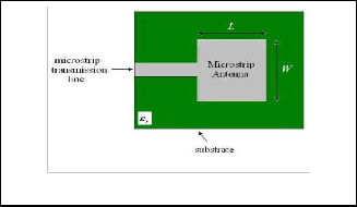
The patch is generally made of conducting material such as copper or gold and can take any possible shape. The radiation pattern is dependent on the patch. Micro- strip patch antennas radiate primarily because of the fringing fields between the patch edge and the ground plane. The radiating patch and the feed lines are usually photo etched on the dielectric substrate. In order to simpl- ify analysis and performance prediction, the patch is gen- erally square, rectangular, circular, triangular, elliptical or some other common shape.
Microstrip patch antennas can be fed by a variety of methods. The four most popular feed techniques used are the microstrip line, coaxial probe, aperture coupling and proximity coupling.The microstrip line feed is used. In this type of feed technique, a conducting strip is con- nected directly to the edge of the microstrip patch as shown in Fig2. The conducting strip is smaller in width as compared to the patch and this kind of feed arrangement has the advantage that the feed can be etched on the same substrate to provide a planar structure. Hence this is an easy feeding scheme, as it provides ease of fabrication and simplicity in modeling.
The basic design considerations for a rectangular patch were considered for the design. The length L of the patch is usually 0.3333λo < L < 0.5λo , where λo is the free- space wavelength. The patch is selected to be very thin such that t << λo (where t is the patch thickness). The height h of the dielectric substrate is usually 0.003λo ≤ h ≤
0.05λo . The dielectric constant of the substrate (εr) is typi- cally in the range 2.2 ≤εr ≤ 12. Formulas used for the patch
design is given below,
Ground Length, Lg = 6h+L (6)
Ground Width, Wg = 6h+W (7)
Substrate height is h and Substrate material choosen is FR4.
The design formulae were used to determine the antenna dimension parameters. This antenna is designed with the
TABLE 1
DIMENSIONS OF ANTENNA
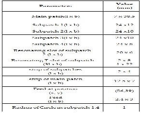
consideration of a main patch connected with four sub- patches to attain the multiband operation characteristics. The detailed parameters attained for the design are shown in Table 1.
c
![]()
2 f r 1
2
IJSER © 2011
International Journal of Scientific & Engineering Research Volume 2, Issue 7, July-2011 3
ISSN 2229-5518
The dimensional parameters are estimated for the multiband antenna design and shown in Table 1. The antenna structure consists of a main patch connected to four sub patches. The four connected sub-patches are designed with slots of various shapes to attain the desired operational bands. The introduction of a slot alters the operational frequency of the radiating structure to attain miniaturization [14], [15].
to operate effectively in the five bands with reduced bandwidths in two of its operating bands.
The antenna structure is fabricated and tested using a simple experimental setup in the laboratory. The experi- mental set up consists of C-Band and X-Band sources connected with microstrip trainer modules comprising of a Directional Coupler, Test Jig, detector unit and suitable R.F connectors with motorized radiation pattern monitor- ing units to record the radiation pattern of the antenna.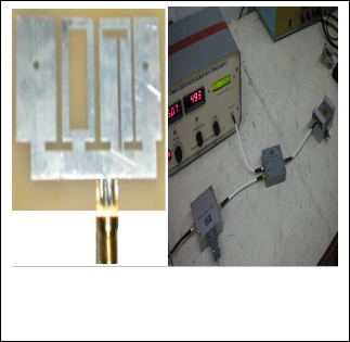
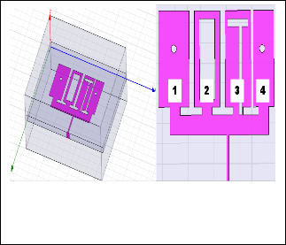
(a) (b)
Fig. 2. (a) Corrugated MSA Design (b) Structure with four slots
The sub-patch1 and sub-patch 4 is designed with a cir- cular slot. The sub-patch 2 is introduced with a rectangu- lar slot and the sub-patch 4 is inserted with a T-shaped slot with a précised dimension to attain the required op- erating band. The structure of the antenna is shown in Fig
3.
The radiating patch is fabricated on a FR4 substrate
with permittivity εr = 4.4. The radiating patch is placed above the ground over the substrate with the height of h
= 2.4mm.The height of the substrate is increased to attain better miniaturization characteristics.
The antenna structure is designed, constructed and si- mulated using simulation software ANSOFT HFSS. The simulation return loss against frequency characteristics result of the antenna is shown in Table II. The antenna is fed with a microstrip line matched to the radiating patches. The position of the microstripline feed is opti- mized by changing the feed location and observed good responses at feed locations at 56mm, 39mm (x,y) with feed length of 2.4mm and feed width of 3mm where it offered good impedance matching.
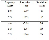
The antenna exhibited good impedance matching in five bands with center frequencies of the bands 1.89 GHz,
5.73 GHz, 7.66 GHz, 8.40 GHz and 9.74GHz. The corres- ponding return loss and bandwidth are shown in Table II. The obtained return loss shows the ability of the antenna
(a) (b)
Fig. 3. (a) Fabricated MSA Design (b) Testing Method
The antenna is connected with the test jig unit using the directional coupler to observe the return loss charac- teristics in the specific bands of operation. The return loss matched with the simulation results in the tested bands.
The antennas are then tested in the free space envi- ronment connected with the radiation pattern monitoring and recording unit which also resulted in a good radia- tion characteristics similar to the simulated radiation cha- racteristics.
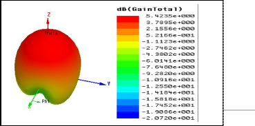
The 3-D radiation characteristics shows good direc-
tional characteristics of the antenna with a gain of 5.4235
dB. The radiation characteristics exhibits good front to back radiation characteristics as the ground plane helps to
reduce the back radiation. The radiation suffered mini- mum sidelobe level with broad beamwidth suitable for wireless applications. The radiation characteristics show the directivity of the antenna reaching a value of 4.7496 dB.
The Return loss against frequency characteristics of the proposed antenna is simulated using Ansoft HFSS and it
IJSER © 2011
International Journal of Scientific & Engineering Research Volume 2, Issue 7, July-2011 4
ISSN 2229-5518
is shown in Fig 4. The characteristics provides good im- pedance matching at five bands with operating frequen- cies centered at 1.89 GHz, 5.73 GHz, 7.66 GHz,8.40 GHz,
9.74 GHz with return loss values less than -10dB and their respective bandwidth in Table 2.
The directivity of the antenna radiation is observed and resulted as 4.7496 dB with omni directional characteris- tics. The radiation makes the antenna more suitable for the present day wireless communication which requires broad beam coverage in a specific direction to provide the required coverage area with minimum antennas.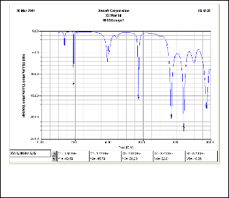
Fig. 6.Directivity
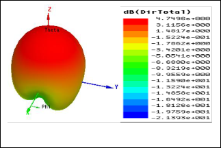
Fig. 4. Frequency vs Return loss
TABLE 2
RETURN LOSS CHARACTERISTICS
The radiation pattern of the antenna is simulated and tested in free space environment using automatic system interface radiation pattern plot generator unit. The tested results resembled the simulated results. The 3-D radiation plot of the antenna is shown in Fig. 5, which shows the peak gain achieved by the antenna in the far field region.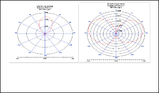
The 2-D polar plots for the E-Field and H-field are shown in the Fig. 7 a) and Fig. 7 b). The E-field pattern gives a wide beam with minor back radiation. The main lobe magnitude has reached more than 2.01 dB.
(a) (b)
Fig. 7.a). E-Field pattern, b). H-Field pattern
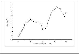
The test is performed for all the bands of frequencies and a frequency against the Gain plot is attained as shown in Fig. 8. The graph shows the antenna achieving a peak Gain of 14.47 dB at 8.37 GHz. Miniaturized antenna suffers from poor gain characteristics and require added circuits or devices to boost up the signals. This compact antenna achieved a high gain in almost all the bands of operation and makes it an attractive candidate for lots of communication applications as it has the capability to pick very weak signals and can radiate effectively into the far field over large distance when compared to miniatu- rized antennas.
R © 2011
ww.ijser.org
International Journal of Scientific & Engineering Research Volume 2, Issue 7, July-2011 5
ISSN 2229-5518
Fig. 8. Frequency vs Gain.
The antenna is designed successfully, simulated and tested with simple experimental approach to study the multiband antenna. The antenna covers the operating frequency band from 1.89GHz to 9.74GHz with good re- turn loss characteristics. The result shows in two of the operating bands the antenna suffered in bandwidth per- formance which can be further optimized to improve. The antenna exhibited good impedance matching in all the operating bands and attained a peak gain of 5.4235 dB. The radiation characteristics resulted with a directivity of
4.7496 dB without sidelobes and possess broad beam- width to provide good coverage in desired directions for communication applications. The attained bands of oper- ation make the antenna most suitable for applications such as UMTS, WLAN, WIMAX communications.
The First author is grateful to Dr. D.S Emmanuel for mo- tivating and guiding in the progress of his research de- gree. Also express his sincere thanks to the Management of VIT University, Vellore and Dr.Sivanthi Aditanar Col- lege of Engineering, Tiruchendur.
[1] Bedri A. Cetiner, Franco De Flaviis, and Luis Jofre, “Miniature Multi-Element Antenna for Wireless Communications”, IEEE Transactions On Antennas And Propagation, Vol. 50, No. 5, May
2002.
[2] Garg, R, Bhartia, P., Bahl, I., and Ittipiboon, A, “Microstrip An- tenna Design Handbook, Artech House, London, 2001.
[3] Kin-Lu Wong, “Compact and Broadband Microstrip Anten-
nas,” John wiley & sons, wiley-interscience publication.
[4] N. Behdad and K. Sarabandi "Bandwidth enhancement and further size reduction of a class of miniaturized slot antennas", IEEE Trans. Antennas Propag., vol. 52, pp. 2004 .
[5] Riku Ma Kinen, Vesa Pyntta Ri, Jouko Keikkinen, And Markku Kivikoski “Improvement of Antenna Isolation In Handheld Devices Using Miniaturized Electromagenteic Band Gap Struc- tures," Microwave and Optical Technology Letters Vol.49, No. 10, Pages 2508-2513, October 2007.
[6] Nader Behdad, Mark Schamberger, Nicholas E. Buris, “Slot Antenna Design for Wireless Communications Systems,” Uni- versity of Central Florida, Orlando, FL 32816, U.S.A.
[7] Amin M. Abbosh , “Miniaturized Microstrip-Fed Tapered-Slot Antenna With Ultrawideband Performance,” IEEE Antennas And Wireless Propagation Letters, VOL. 8, 2009.
[8] Eldek, A. A., A. Z. Elsherbeni, and C. E. Smith, “Square slot
antenna for dual wideband wireless communication systems,"
Journal of Electromagnetic Waves and Applications, Vol. 19, No. 12,
1571-1581, 2005.
[9] Wang Ren, Zhiguo Shi,Yu Li,and Kangsheng Chen “Compact Dual- Band T-Slot Antenna for 2.4/5 GHz Wireless Applications,” pages
2493-2497, 2006 IEEE.
[10] Amit A. Deshmukh and K. P. Ray, “Compact Broadband Slot- ted Rectangular Microstrip Antenna,” IEEE Antennas And Wireless Propagation Letters,VOL.8,2009.
[11] Haiwen Liu, Shohei Ishikawa, An An, Satoshi Kurachi, and Toshihiko Yoshimasu, “Miniaturized Microstrip Meander-line Antenna with very high-permittivity substrate for Sensor appli- cations,” Microwave And Optical Technology Letters, Vol. 49, No. 10, October 2007.
[12] H.S. Al- Raweshidy, M. J. Alexander, D. Budimir, R. Nilavalan, K. M. Nasr and H. F. A. Tarboush “A Compact Printed Anten- na for Multiband Wireless Applications”, in IEEE,2010.
[13] Dalia Nashaat, Hala A. Elsadek, Esmat Abdallah,Hadia Elhe- nawy and Magdy F.Iskander , “Multiband and Miniaturized Inset Feed Microstrip Patch Antenna Using Multiple Spiral- Shaped Defect Ground Structure (DGS)”, PIERS Proceedings, Moscow, Russia, August 18-21, 2009.
[14] M. F Abdul Kadir, M. Z. A. Abdul Aziz, M.R. Che Rose, M. S.
R. Mohd Shah, D. Misman, M. K Suaidi, “Dual Polarization In- set-Fed Microstrip Patch Antenna,” Asia-Pacific conference on electromagnetic proceeding 2007.
[15] Md. Fokhrul Islam, M. A. Mohd. Ali, B. Y. Majlis and N. Mi- sran, “Design, Simulation and Fabrication of a Microstrip Patch Antenna for Dual Band Application”, 5th International Confe- rence on Electrical and Computer Engineering ICECE 2008, 20-
22 December 2008, Dhaka, Bangladesh.
IJSER © 2011