International Journal of Scientific & Engineering Research, Volume 4, Issue 12, December-2013 203
ISSN 2229-5518
Priyanka C P, Sija Gopinathan
—————————— ——————————
The arrival of new switching device, digital
technology and microprocessor popularise use of
BLDC in electric/hybrid vehicle, ship propulsion,
IJSER
components contained in any industrial system. EMA are now a days widely used in industry for various applications. In aerospace it is mainly used in flight control system of missiles, aircraft or launch vehicles. The EMA is gaining more importance than hydraulic actuator due to technology advance in permanent magnet brushless dc motor with new magnetic materials and motor drive controllers with power semiconductor switching.The high efficient BLDC motor and ball screws composing the key part of EMA [3]. The DC motor is simplest and efficient motor used in EMA due to ease of control and low cost in manufacturing compared to other motors. The limitation of DC motor in reliability and robustness due to wear of brush and commutation. So it need time to time replacement. In aerospace and industrial application where high reliability and robustness required the brush dc motors.
—————————————
Priyanka C P is currently Pursuing M.Tech in Power Electronics in Mar Athanasius College of Engineering, M G university, Kerala,
India. EMAIL priyanka.cp03@gmail.com
and industrial applications [1]-[4]. Permanent
magnet ac motors are classified as sinusoidally fed Permanent synchronous motors and rectangular fed permanent magnet brushed dc motor. The construction of BLDCM is inside-out version of dc motor. The winding of BLDCM is wound in such a way that trapezoidal back emf is produced. The quasi rectangular current should fed to motor to produce constant torque.[1]
In this paper EMA based position control system is presented. The EMA consists of electrical part as three phase BLDCM and mechanical part as ball screw. The motor and ball screw is connected using suitable gearing system. The BLDCM provides high efficient operation. This paper explains the modeling of three phase BLDCM and drive, closed loop position control system is included. The parameter values are selected based on specification. The position control is done using PI feed back controller and tuning is done using cohen coon method. The simulation results are presented Matlab/Simulink. Finally the BLDCM model is
IJSER © 2013 http://www.ijser.org
International Journal of Scientific & Engineering Research, Volume 4, Issue 12, December-2013 204
ISSN 2229-5518
extended to EMA model used in aerospace and automative industry.
Fig. 1 Bloc k Diagram of Position control Scheme
𝐿𝑎𝑏 = 𝐿𝑏𝑎 = 𝐿𝑎𝑐 = 𝐿𝑐𝑎 = 𝐿𝑏𝑐 = 𝐿𝑐𝑏 = 𝑀
Considering stator phase current balanced
𝑖𝑎 + 𝑖𝑏 + 𝑖𝑐 = 0
The equation of voltage can written as![]()
𝑉 = 𝑅𝑖 + (𝐿 − 𝑀) 𝑑𝑖𝑎 + 𝐸 (4)
𝑑𝑡
![]()
𝑉 = 𝑅𝑖 + (𝐿 − 𝑀) 𝑑𝑖𝑏 + 𝐸 (5)
𝑑𝑡
![]()
𝑉 = 𝑅𝑖 + (𝐿 − 𝑀) 𝑑𝑖𝑐 + 𝐸 (6)
𝑑𝑡
The motion for a simple system with moment of
inertia J and damping coefficient B and load
torque 𝑇𝑙 can be written as
𝑑𝜔𝑚
The assumptions made are all the three phase
windings are symmetrical, Eddy current loss and
𝑇𝑒 − 𝑇𝑙 = 𝐽
![]()
+ 𝐵𝜔 (7)
𝑑𝑡
hysteresis loss are neglected, Magnetic saturation is not taken into account. The Stator resistance R, Self
The rotor position and rotor speed can be related as
inductance L, MutIal induJctance M.
SE𝑑𝜃𝑟 = 𝑃 ∗ 𝜔R(8)
![]()
![]()
𝑑𝑡 2 𝑟
Fig. 2 Equivalent circuit of three phase BLDCM
The three phase balanced stator voltage equation can be expressed as follows
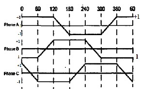
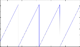
Fig. 3 Back Emf waveform of three phase BLDC
The back emf function can be written as
𝑑 𝑖𝑎
𝑑𝑖𝑏
𝑑𝑖𝑐
𝑓𝜃𝑟 = 1 0 ≤ 𝜃𝑟 ≤ 2𝜋/6
![]()
![]()
![]()
𝑉𝑎 = 𝑖𝑎 𝑅𝑎 + 𝐿𝑎𝑎 𝑑𝑡 + 𝐿𝑎𝑏 𝑑𝑡 + 𝐿𝑎𝑐 𝑑𝑡 + 𝑒𝑎 (1)
= 1 2𝜋/6 ≤ 𝜃𝑟 ≤ 4𝜋/6
𝑑𝑖𝑏
𝑑𝑖𝑎
𝑑𝑖𝑐
![]()
![]()
![]()
𝑉𝑏 = 𝑖𝑏 𝑅𝑏 + 𝐿𝑏𝑏 𝑑𝑡 + 𝐿𝑏𝑎 𝑑𝑡 + 𝐿𝑐𝑏 𝑑𝑡 + 𝑒𝑏 (2)
6 4𝜋 6𝜋
![]()
![]()
![]()
= (𝜋 − 𝜃𝑟) � � ≤ 𝜃𝑟 ≤
(9)
𝑑 𝑖𝑐
𝑑 𝑖𝑎
𝑑 𝑖𝑏
𝜋 6 6
![]()
![]()
![]()
𝑉𝑐 = 𝑖𝑐 𝑅𝑐 + 𝐿𝑐𝑐 𝑑𝑡 + 𝐿𝑐𝑎 𝑑𝑡 + 𝐿𝑐𝑏 𝑑𝑡 + 𝑒𝑐 (3)
Considering three phase symmetry and non salient
rotor
𝐿𝑎𝑎 = 𝐿𝑏𝑏 = 𝐿𝑐𝑐 = 𝐿
= −1 6𝜋/6 ≤ 𝜃𝑟 ≤ 8𝜋/6
= −1 8𝜋/6 ≤ 𝜃𝑟 ≤ 10𝜋/6
![]()
6
= (𝜃𝑟 − 2𝜋) ( ) 10𝜋/6 ≤ 𝜃𝑟 ≤ 12𝜋/6
𝜋
IJSER © 2013 http://www.ijser.org
International Journal of Scientific & Engineering Research, Volume 4, Issue 12, December-2013 205
ISSN 2229-5518
Similarly equation for other phases as functions of rotor
position are written. The above equation can be used to model the three phase BLDC motor.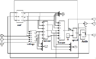
Fig. 4 Model of three phase BLDC
TABLE I
Commutation Sequence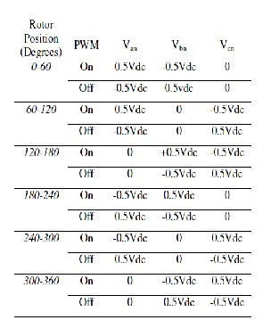
The electric commutation means a way of PWM signal
distribution to switches in inverter circuit. The sequencing depends upon signal which are sensed and feedback. The other factor it depends on is kind of PWM signal
(unipolar/bipolar). The commutating logic is implementing
using logic gates and output can be provided as driving signal for switches in the inverter. The position of rotor is sensed over every 60 degree interval.
The commutating logic was developed using sensing rotor position. After determining the rotor position it will start giving driving signals for switches in the inverter. By this a
120 degree conduction signal generator mode is implemented which can generate exact square wave switching patterns. The frequency of carrier signal is
5KHZ. The inverter is driven by 6 gating signal derived
from the commutating logic.The diagram shows a three phase inverter and the output of three phase feed the three phase BLDC motor.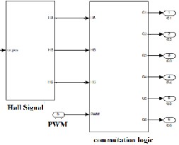
Fig.5 Commutation Logic
The inverter in the system is modelled by considering conduction 120 degree. Two phases conduct at a time in such a way that the inverter divides the supply voltage between two conducting phases. Bipolar switching is used.
Fig. 6 Voltage Source Inverter
The gating pulses to the switches in the inverter is given according to the rotor position sensed by hall sensor and bipolar PWM switching is used. At each rotor position according to signals two phases conducts a positive and a negative phase
IJSER © 2013 http://www.ijser.org
International Journal of Scientific & Engineering Research, Volume 4, Issue 12, December-2013 206
ISSN 2229-5518
The compensation selected for postion controlling is PI compensation. Integral compensation reduces steady state error and tracking position which increases the accuracy of the system. The tuning method used is Cohen coon method.
Fig. 7 Switching Action
Fig. 10 Position Controller
Fig. 8 Electromechanical Actuator
The model of closed loop system of three phase BLDC is explained and simulation work have been conducted. The
electrical input corresponding to actuator position is
IJSER
The three phase motor which forms the electric part of![]()
![]()
motor is then connected to a ball screw through a proper gearing mechanism. The function of gearing mechanism is to reduce the angular velocity before converting into linear displacement. This constitute the mechanical part. The electromechanical actuator model thus consist of a three phase BLDC, PWM generator, Inverter, Position feedback and a gear box mechanism
obtained as shown in figure. The simulation result of
backemf , current , position are shown below.
200
0
-200
0.3 0.305 0.31 0.315 0.32 0.325
200
0
Fig. 9 Model of Electromechanical Actuator
-200
0.3 0.305 0.31 0.315 0.32 0.325
![]()
200
0
-200
0.3 0.305 0.31 0.315 0.32 0.325
Time (sec)
Fig 11.Emf
5
0 ![]()
-5
0.25 0.255 0.26 0.265 0.27 0.275 0.28 0.285 0.29 0.295 0.3
5
0 ![]()
-5
0.25 0.255 0.26 0.265 0.27 0.275 0.28 0.285 0.29 0.295 0.3
5
0 ![]()
-5
0.25 0.255 0.26 0.265 0.27 0.275 0.28 0.285 0.29 0.295 0.3
Time(sec)
Fig. 12 Current
IJSER © 2013 http://www.ijser.org
International Journal of Scientific & Engineering Research, Volume 4, Issue 12, December-2013 207
ISSN 2229-5518
![]()
2 2
0
-2
0.25 0.3 0.35 0.4 0.45 0.5 0.55 0.6 0.65 0.7
2
0 ![]()
-2
0.25 0.3 0.35 0.4 0.45 0.5 0.55 0.6 0.65 0.7
2
0 ![]()
-2
0.25 0.3 0.35 0.4 0.45 0.5 0.55 0.6 0.65 0.7
Time(sec)
Fig. 13 Hall Signal
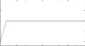
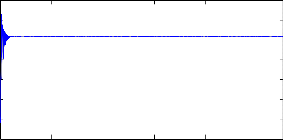
1.5
1
0.5
0
0 0.2 0.4 0.6 0.8 1 1.2 1.4 1.6 1.8 2
Fig. 17 Position Control for an input of 1V
400
350
300
250
200
150
100
50
0
The EMA based position control system is
designed. The results of simulation are also presented. The modelling of a three phase BLDC motor is done. The results from simulation shows it is fit with theoretical studies. The position controller provided will give a stable response with rise time less than 200ms and reduced steady state error.
REFERENCES
0.5 0.6 0.7 0.8 0.9 1
Time(seconds)
Fig. 14 Position
10
8
6
4
2
0
-2
0 0.1 0.2 0.3 0.4 0.5
Time(seconds)
Fig. 15 Torque
600
500
400
300
200
100
0
-100
0 0.1 0.2 0.3 0.4 0.5
Time
[1] P. Pillay and R. Krishnan, “Application characteristics
of permanent magnet synchronous and brushless DC
motors for servo drives,” IEEE Trans.Ind. Appl., vol. 27, no.
5, pp. 986–996, Sep/Oct. 1991.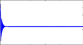
[2] P. Pillay and R. Krishnan, “Modeling of permanent
magnet motor drives,”IEEE Trans.Ind. Electron., vol. 35, no.
4, pp. 537–541, Nov. 1988.
[3] Anas S R, HemanthJaison, Anish Gopinath, M.N
Namboothiripad, M.P Nandakumar(2011)“ Modelling and simulation analysis of a redundant electromechanical actuator bases positionservo system” International
conference on computer communication and electrical technology
[4] P. Pillay and R. Krishnan, “Modeling, simulation, and
analysis of permanent-magnet motor drives, part ii. The brushless dc motor drive,”IEEE Trans. Ind. Appl., vol. 25, no. 2, pp. 274–279, Mar./Apr.1989.
[5]L.Parsa and H. Toliyat, “Multi-phase permanent-magnet
motor drives,” IEEE Trans. Ind. Appl., vol. 41, no. 1, pp. 30–
37, Jan./Feb. 2005.
[6] L. Parsa, “On advantages of multi-phase machines,” in
Proc. IEEE Ind.Electron. Soc. Annu. Conf., Nov. 2005, pp.
1574–1579.
[7] R.Krishnan, Electric Motor Drives Modelling, Analysis and Control©2001 Prentice Hall, India.
Fig. 16 Speed
IJSER © 2013 http://www.ijser.org