International Journal of Scientific & Engineering Research Volume 2, Issue 10, Oct-2011 1
ISSN 2229-5518
Modeling Anisotropy and Steady State Creep in a Rotating Disc of Al-SiCp having Varying Thickness
Vandana and S.B. Singh
Abstract: The analysis of steady state creep in a rotating disc made of Al-SiCp composite having variable thickness has been carried using Sherby’s constitutive model. The creep parameters have been evaluated using the available experimental results in the literature using regression analysis. Three variations in the thickness (constant, linearly and hyperbolic varying thickness) of the disc have been considered while keeping other material parameters same. The change in the radial stress in all the three cases is not significant while the tangential stress is changed with the change in the values of anisotropic constants. The tangential strain rates are highest at the inner radius of the disc and then decreases towards the outer radius of the discs. The radial strain rate which is compressive in nature becomes tensile in middle of the disc for some specific values of anisotropic constants. The study reveals that the anisotropy and thickness profile has a significant effect on the creep behavior of rotating disc. Thus for the safe design of the rotating disc the effect of anisotropy and profile should be taken care of.
Keywords: Modeling, Composites, Rotating Disc, Steady Strain Creep Rate
1 INTRODUCTION
—————————— ——————————
steel at 1000 F using Von Mises and Tresca yield
Theoretical investigation of the stresses in solid and
annular discs rotating at high speeds have received
widespread attention due to a large number of
applications in engineering like turbine motors, flywheels, gears, shrink fits etc. They are usually operated at relatively higher angular speed and high temperature. Therefore the prediction of long term steady state creep deformation is very important for these applications.
Turbine discs are usually designed by decreasing the
thickness with increasing radius. This feature
introduced a disc with varying thickness for using
the material of disc more effectively. It is shown that the analysis of creep behavior in a disc with varying thickness is complicated than that of a disc with constant thickness.
Wahl et al. [1] have theoretically studied steady state
creep described creep behavior by a power function in a rotating turbine disc made of 12% chromium

Dr S.B. Singh, is Professor and Head, Department of Mathematics, Punjabi University, Patiala-147002, INDIA, Email ID: sbsingh69@yahoo.com. His research interests are Mathematical Modeling in Composite Material and Optimization Techniques. He has published 50 research papers in Journals/Conference Proceedings. He was awarded Khosla Gold Medal by I.I.T. Roorkee for his outstanding research contributions.
Ms.Vandana is a Ph.D. student in the Department of
Mathematics, Punjabi University, India, Punjab, Patiala-
147002. vaggarwal2584@gmail.com.
criteria and validated their results experimentally. Ma [2,3] have carried out creep analysis of solid disc. The analysis shows that by changing the profile of disc, stress is quite different from those observed in a disc of constant thickness. Arya and Bhatnagar [5] have carried out creep analysis of orthotropic rotating disc using constitutive equations and a time hardening law. It is reported that the tangential stress at any radius and the tangential strain rate at the inner radius decrease with increasing anisotropy of the material. Nieh et al. [6] has shown that an aluminum based composite containing silicon carbide whisker has better creep resistance compared to the base aluminum alloy. Jerzy Biakiewicz [7] has presented a theoretical analysis of the finite strains in a rotating discs followed by damage and creep rupture front motion as described by Kachanov’s hypothesis. The creep is represented by the generalized Norton-Odqvist law. Bhatnagar et al. [9] have performed steady state creep analysis of orthotropic rotating discs having constant thickness, linearly varying thickness and hyperbolically varying thickness. They have used Norton’s power law to describe creep behavior of the disc material. Pandey et al. [10] have studied the steady-state creep behavior of Al–SiCp composites under uniaxial loading condition in the temperature range between
623K and 723K for different combinations of particle size and volume fraction of reinforcement and found that the composite with finer particle size has better creep resistance than that containing coarser ones. Gupta et al. [11] have obtained creep stresses and strain rates in thin rotating disc having variable
IJSER © 2011 http://www.ijser.org
International Journal of Scientific & Engineering Research Volume 2, Issue 10, Oct-2011 2
ISSN 2229-5518
thickness and variable density by using Seth’s transition theory. It is observed that a rotating disc whose density and thickness ratio decreases radially is on the safer side of the design in comparison to a flat disc having variable density. Singh and Ray [12] have analyzed steady state creep in an anisotropic composite disc showing Bauschinger effect, using Norton’s power law and newly proposed yield criterion. This yield criterion results in significant changes in the tangential stress distribution but similar radial stress distributions in disc with residual stress compared to those obtained in a similar disc without residual stress following Hill’s yield criterion. The presence of tensile residual stress in the disc is observed to increase the creep rate significantly compared to that in a similar anisotropic disc without residual stress. Orcan and Eraslan [13] investigated the distribution of stress, displacement and plastic strain in a rotating elastic–plastic solid disk of variable thickness in a power function. The analysis is based on Tresca's yield condition, its associated flow rule and linear strain hardening material behavior. By employing a variable thickness disc the plastic limit angular velocity increases and the magnitude of stresses and deformations in the disc reduces. Gupta et al. [14] have analyzed steady state creep in isotropic aluminum silicon carbide particulate rotating disc. The creep behavior has been described by Sherby’s law. It is observed that the tangential as well as radial stress distribution in the disc do not vary significantly for various combinations of material parameters and operating temperatures. The tangential as well as radial strain rates in the disc reduces significantly with reducing particle size,
processing or inhomogeneous distribution of reinforcements has been investigated. The presence of anisotropy leads to significant reduction in the tangential and radial strain rates over the entire disc and helps in restraining creep response both in the tangential and in the radial directions. Rattan et al. [18] have reported that the creep exponent should be taken as 8. Chamoli et al. [19] have studied the effect of anisotropy on the stress and strain rates and concluded that the anisotropy of the material has a significant effect on the creep of a rotating disc. Keeping in view, all the above studies for a disc of constant thickness, an effort has been made to study effect of anisotropy on a rotating composite disc with varying thickness by taking creep exponent 8. The volume of all the discs is kept the same. Steady state creep has been analyzed using the Sherby’s constitutive model
2. ASSUMPTIONS
For the purpose of analysis the following assumptions are made:
1. Material of disc is orthotropic and incompressible
2. Elastic deformations are small for the disc and therefore they can be can be neglected as compared to creep deformation.
3. Axial stress in the disc may be assumed to be zero as thickness of disc is assumed to be very small compared to its diameter.
4. The composite shows a steady state creep behavior , which may be described by following sherby’s law:

0
increasing particle content and decreasing operating
temperature. Jahed et al. [15] observed that the use of
variable thickness disc helps in minimizing the
where,
As
E
3
weight of disc in aerospace applications. There are numerous applications for gas turbine discs in the

A A D
s | b |5
aerospace industry such as in turbojet engines. These
discs normally work under high temperatures while


where , , n ,
0 , A, D
, , b , E
be the effective
subjected to high angular velocities. Minimizing the weight of such items in aerospace applications results in benefits such as low dead weights and lower costs. Baykara [16] explained the stress concentration factors at a small circular hole in a large sheet of plastic anisotropy, subjected to equi-biaxial tension.
strain rate, effective stress, the stress exponent,
threshold stress, a constant, lattice diffusivity, the sub
grain size, the magnitude of burgers vector , Young’s
modulus.
The above equation may be expressed as
In this analysis an orthotropic yield function suggested by Hill and approximate solution

M
where,

n
(1)
technique developed by Durban are used. Numerical
results for aluminum and copper sheets are presented.
Singh and Ray [17] have performed creep analysis in an anisotropic 6061Al-20Wt% SiCw composite disc rotating at 15,000 rpm and undergoing steady state creep at 561K following Norton’s power law. The effect of anisotropy induced presumably by
A 1 / n
M s is Creep Parameter.
E
5. Material of disc yield according to Hill’s Criterion
for anisotropic material as given by
IJSER © 2011 http://www.ijser.org
International Journal of Scientific & Engineering Research Volume 2, Issue 10, Oct-2011 3
ISSN 2229-5518
1
F(
)2 G(
)2 H(
1/ 2
)2
z


(F G ) z
G r
F
(7)

(GH)

r 2
where F, G and H are anisotropic constants of the

where F, G and H are anisotropic constants. be the
material.
r ,
,
z
and
r ,
,
z are the
effective stress. For biaxial state of stress, the effective
strain rates and the stresses respectively in the
stress is,
1/ 2
direction

r , and z . be the effective strain rate
1 2 2
2 and be the effective stress.

G H F
Gr
H r
(2)

4. ANALYSIS
In Particle reinforced composite, the material
Using Eqs. (1) and (2), Eq. (5) can be rewritten as,
parameters m and 0
depend on the particle size
F GH
x
M
and the percentage of dispersed particles apart from

G H


( )


8
the temperature, have been obtained by using the
experimental results of Pandey et al. [10].
r

dur
F F
F
1/ 2
(8)
The following regression equations have been extracted from the available experimental results,
d r
where,
G

F
H 2 H


x 2
F F

x G
F
H

m e 35 .38 P 0 . 2077 T
4 . 98 V 0 . 622

x(r )
0 0.03507P 0.01057T 1.00536V 2.11916
3. FUNDAMENTAL RELATIONS
Similarly from Eq. (6),
Consider a thin orthotropic composite disc of

H H


(
( 8
6061 Al-SiCp of density and rotating at a constant
F G H

x M 0
angular speed radian/sec. The thickness of the disc

ur
F F
1 / 2
(9)
is assumed to be h and a and b be inner and outer
r H

F
G 2 H


x 2
F F
x
H

F
radii of the disc respectively. Let I and
I 0 be the
moment of inertia of the disc at inner radius a and outer radius r and b respectively. A and A0 be the
area of cross section of disc at inner radius a and
z
r
(10)
outer radius r and b respectively. Then
Dividing (8) by (9),
G H H


r b x
I h r 2 dr,
I h r 2 dr


(r) F F F
(11)
a a
1
r b
H H x


F F
A h d r ,
a
A0 h dr
a
(3)
where,
1 h
dr .
(4)
(r)
du r . r

avg


d r u
A0 a r
The constitutive equations for an anisotropic disc
under multiaxial stress condition are given as,

du r

u r

(r ) dr r
r

(G H ) r
2

H G z
(5)
Integrating and taking limit a to r on both sides,
r

( H F )
2
F z
H r
(6)
ur
u r
exp .
a

(r) dr r
(12)
IJSER © 2011 http://www.ijser.org
International Journal of Scientific & Engineering Research Volume 2, Issue 10, Oct-2011 4
ISSN 2229-5518
Dividing Eq. (12) by r and equated to Eq. (9),
Substituting
from Eq. (15) into (4),
0

(u r
)1 / 8
(r)
(13)
u
1/8
A0 σ θ
avg
b
ψ2 (r) . hdr
a
(20)
M
where,


i
M b
1
a
(r). hdr
x 1/2
1/8
Using Eq. (19) and (20), Eq. (15) becomes,
H G 2H


x 2

1 H
2
F F F F
r φ(r)dr
b
ψ(r) .

r

exp.
1 (r)
2 I
2 (r) . hdr
H H
F(GH)1 x
a r
a


F F
(14)

b
1 (r). hdr
a
2 (r)
(21)

Substituting from Eq. (2) to Eq.(13), it gives,
Integrating Eq. (18) within limits a to r and use
Eq.(3),
1/8
1 r
1/2


uri
r

r . h . h dr I
(22)
F G


H x2
2H x
H
1

σ σ
ψ(r)
GF F F
F G
θ 0
Thus the tangential stress and radial stress r
are determined by Eqs. (21) and (22). Then strain
1 / 8
rates r , and z
calculated from equations (5), (6)
u ri
M
1 (r) 2 (r )
(15)
and (7).
(5.1) DISCS WITH LINEARLY VARYING THICKNESS
(r) (r)
1/ 2
(16)
The thickness h is assumed to be of the form
F
G H
H H


x2


2 x 1
GH F F
F F
and
h hb 2 c b r ,
2(r)
F

0
G H H
1/ 2
H
(17)
ha
hb 2 c b a


x2

2 x 1
where c is the slope of a disc and the values of c
GH F F
F F
appearing in above equation are calculated as
0.002859.
5. EQUATION OF EQUILIBRIUM
The equation of equilibrium for a rotating disc with varying thickness can be written as,
Using expression, the Eq. (3) becomes,
A r a hb c 2b r a

d r h
dr r
h
2 r 2 h 0
(18)
A b a h
c b a
Integrating Eq. (18) within limits a to b and using
Eqs. (3) and (4),
I 0

hb (b 3 a 3 )
3
2cb

3
(b 3 a 3 )

c (b 4 a 4 )
2
avg

1 2 I A0
(19)

I hb
3
(r 3
a 3 )
2cb

3
(r 3
a 3 )

c (r 4
2
a 4 )
IJSER © 2011 http://www.ijser.org
International Journal of Scientific & Engineering Research Volume 2, Issue 10, Oct-2011 5
ISSN 2229-5518
(5.2) DISCS WITH HYPERBOLIC VARYING THICKNESS
Using the expression for thickness, the Eq. (3)
becomes,
r m 1 a m 1
b m 1 a m 1
The thickness h can be written in the form h
c r m

A c ,
A0

c
where c and m are constants and the values of c
m 1
m 3
m 3
m 3
m 1
m 3
and m appearing in above equation are calculated as
r
I c
a
,
b
I c
a
31.26 and - 0.74 respectively.

m 3

0 m 3
Thickness V ariation
3
Legends:
C onsta nt Thickness
Linearly V ary ing Thickness
Hy perbolic Varying Thickness
2
1
0
20 40 60 8 0 10 0 12 0 1 40 1 60
Radial Distance (mm)
Figure 1: Variation of disc thickness with radial distance for different discs.
6. SOLUTION PROCEDURE
by
which can be substituted in Eq. (11) to
calculate first approximation of
(r)
i.e. [ (r)] 1 .
The stress distribution is evaluated from the above
analysis by iterative numerical scheme of
computation. In the first iteration, it is assumed that
Now one carries out the numerical integration of (r) from limits of a to r and uses this value in
Eq.(14) to obtain first approximation of (r)
i.e.
avg
over the entire disc radii. Substituting
(r )
Using this
(r ) , in Eq. (16) and (17)
for
avg
in Eq. (22) the first approximation value
respectively, [ 1 ( r )]1 are found, which are used in
of r i.e. [ r ]1 is obtained. The first approximation
of stress ratio, i.e. [ x]1 , is obtained by dividing [ r ]1
Eq. (15) to find second approximation of
i.e.
[ ]2 . Using
[ ]2
for
in Eq. (22), second
IJSER © 2011 http://www.ijser.org
International Journal of Scientific & Engineering Research Volume 2, Issue 10, Oct-2011 6
ISSN 2229-5518
approximation of r i.e. [ r ]2 is found and then the second approximation of x ie. [ x]2 is obtained.
LEGENDS:
ITER = Iteration no
h = Limiting value of Err (=0.01)
ITM = Maximum no of iterations
The iteration is continued till the process converges and gives the values of stresses at different points of the radius grid.
For rapid convergence 75 percent of the value of
obtained in the current iteration has been mixed with
25 percent of the value of obtained in the last
iteration for use in the next iteration i.e
next .25 previous .75 current . The strain rates are
ERR
ITER
-
ITER -1
then calculated now from the Equations (8), (9) and

ITER -1
(10).
7. ANISOTROPIC CONSTANTS AND NUMERICAL COMPUTATIONS
For the sake of computation, we have chosen material
parameters as particle size
P 1.7 m
, particle
content
V 30%
and temperature
T 623 K as
reported in Pandey et al.[10]. The stress exponent and
Density of disc material have been taken as n 8 and
2862.1kg / m 3 . The inner radii a and the outer radii b of all the discs are taken as 31.75 mm and
152.4 mm respectively. The anisotropic constants
have been taken from [7] and the numerical results
have been calculated for two cases of anisotropy each
deviating from isotropy. The remaining two cases of anisotropy are almost similar and hence they have been omitted for computational purpose.
Table 1: Anisotropic Constants

Case 1 Case 2 Case 3 Case 4 Case 5
G/F .8159 1.200 1.000 .7452 1.34

H/F .6081 .7452 1.000 1.2200 1.64
8. EFFECT OF DISC PROFILE ON ANISOTROPIC DISC
The effects of varying the disc thickness on creep behavior of composite disc made of anisotropic material (6061Al - 30% vol SiCp) are shown in Figures
8.1 – 8.4. These graphs show the variation in stresses and strain rates. In disc for anisotropic material, the
thickness have been taken as
ha 1.0mm to
Figure 2. Numerical scheme of computation.
hb 1.0mm
hb 0.75mm
hb 0.76mm
(Constantly), (Linearly) and
(Hyperbolically)
ha 1.44 mm to
ha 2.42mm to
IJSER © 2011 http://www.ijser.org
International Journal of Scientific & Engineering Research Volume 2, Issue 10, Oct-2011 7
ISSN 2229-5518

Legends:
Constant Thickness
Case 1
Case 3
Case 5
Linearly Varying Thickness
Case 1
Case 3
Case 5
Hyperbolic Varying Thickness
Case 1
Case 3 case 5


Constant Thickness Linearly Varying Thickness Hyperbolic Varying Thickness
75
70
65
60
55
50
45
40
20 40 60 80 100 120 140 160
Radial Distance (mm)
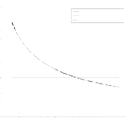
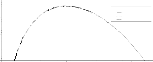
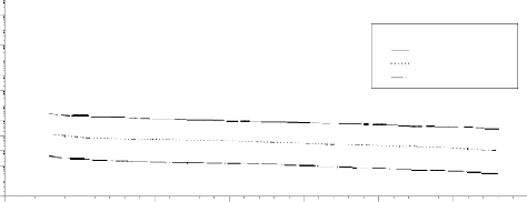
Figure 8.1 Variation of tangential Stress along the radial distance of the discs rotating with an angular velocity 15000 rpm at 623K.
Figure 8.1 shows the variation of tangential stress in a rotating disc along the radius in the disc for two different cases of anisotropy and three thickness profiles. The tangential stress in the inner and outer part of disc is lowest in case 5 and highest in case 1, while it lies in between the two in case 3. In the middle part of the disc, the tangential stress is lowest
in case 1 and highest in case 5, while it lies in between the two in case 3. The trend of variation of tangential stress is similar in all cases of thickness profile variations. The tangential stress in anisotropic rotating disc having hyperbolic thickness is reduced everywhere compared to disc of uniform thickness and linearly varying thickness.
IJSER © 2011 http://www.ijser.org
International Journal of Scientific & Engineering Research Volume 2, Issue 10, Oct-2011 8
ISSN 2229-5518
2 8
Legend s:
2 4 C on stan t Th ic kn e ss
C as e 1
2 0 C a se 3
C a se 5
1 6
1 2
8

4
0
20 4 0 6 0 8 0 1 0 0 1 20 1 4 0 1 60
2 8
L egend s:
2 4 L in ear ly V ar yin g Th ic kn e ss
C ase 1
2 0 C a se 3
C a se 5
1 6
1 2
8
4
0
28 20 4 0 60 8 0 10 0 1 20 14 0 1 60
L egend s:
24 H yp er b olic Va rying Th ick n ess
C a se 1
C a se 3
20 C a se 5
16
12
8
4
0
2 0 40 6 0 80 1 0 0 12 0 1 4 0 16 0
R a dial D istan ce (mm )
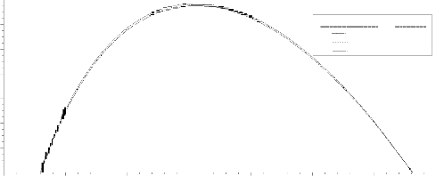
Figure 8.2 Variation of radial stress in rotating discs along the radius of the disc rotating with an angular velocity 15000 rpm at 623K.
Figure 8.2 shows the variation of the radial stress in rotating disc along the radius of the disc. The radial stress is not much affected by introducing anisotropy in the disc as the values of radial stress are very close for all the different cases of anisotropic constants and the effect of disc profile on radial stress is similar to
disc made of isotropic composite. The disc having hyperbolically varying thickness has lower radial stress than uniform thickness disc, but litter higher than the disc with linearly varying thickness near the inner radius of disc, but towards the outer radius the radial stress is the highest.
IJSER © 2011 http://www.ijser.org
International Journal of Scientific & Engineering Research Volume 2, Issue 10, Oct-2011 9
ISSN 2229-5518
1e+0
1e-1
1e-2
1e-3
1e-4
1e-5
1e-6
1e-7
1e-8

1e-9
1e-10
1e-11
1e-12
1e-13
1e-1
1e-2
1e-3
1e-4
1e-5
1e-6
1e-7
1e-8
1e-9
1e-10
1e-11
1e-12
1e-13
1e+0
1e-1
1e-2
1e-4
1e-5
1e-6
1e-7
1e-8
1e-9
1e-10
1e-11
1e-12
1e-13
Legends:
Constant Thickness
Case 1
Case 3
Case 5
20 40 60 80 100 120 140 160
Legends:
Linearly Varying Thickness
Case 1
Case 3
Case 5
20 40 60 80 100 120 140 160
Legends:
Hyperbolic Varying Thickness
Case 1
Case 3
Case 5
20 40 60 80 100 120 140 160
Radial Distance (mm)
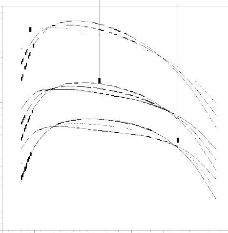
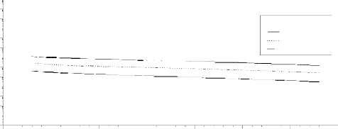
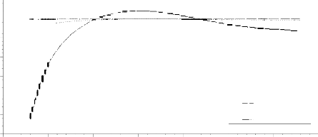
Figure 8.3 Variation of tangential strain rate along the radial distance of the disc rotating with an angular velocity 15000 rpm at 623K.
Figure 8.3 shows that the variation of tangential strain rate along the radius of the disc. In all the cases of thickness variations, the tangential strain rate is highest at the inner disc and then decreases continuously when one moves towards the outer disc. In all cases of thickness profile variation, the tangential strain rate is maximum in the case 1 of anisotropy and minimum in the case 5 of anisotropy. The values of tangential strain rate in case 3 of
anisotropy always lie between these two. Therefore the anisotropy of type 5 helps to decrease the tangential strain rate. In case of hyperbolic variation of thickness of the disc, the tangential strain rate is relatively less compared to the strain rate in other two variations in the thickness of the disc. Thus the combination of anisotropic of type 5 with hyperbolic varying thickness yields less tangential strain rate.
IJSER © 2011 http://www.ijser.org
International Journal of Scientific & Engineering Research Volume 2, Issue 10, Oct-2011 10
ISSN 2229-5518
1e-9
0e+0
-1e-9
-2e-9
-4e-9

-5e-9
-6e-9
0e+0
-1e-8
-2e-8
-3e-8
-4e-8
Legends:
Constant Thickness
Case 1
Case 3
Case 5
20 40 60 80 100 120 140 160
Legends:
Linearly Varying Thickness
Case 1
Case 3
Case 5
-5e-8
20 40 60 80 100 120 140 160
0e+0
-1e-7
-2e-7
-3e-7
-4e-7
-5e-7
Legends:
Hyperbolic Varying Thickness
Case 1
Case 3
Case 5
-6e-7
20 40 60 80 100 120 140 160
Radial Distance (mm)
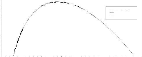
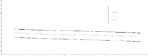
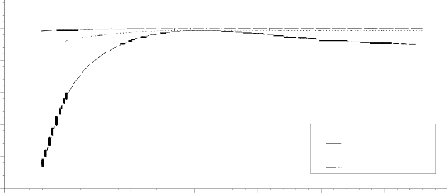
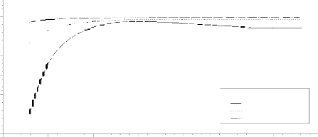
Figure 8.4 Variation of radial strain rate along the radial distance of the discs rotating with an angular velocity 15000 rpm at 623K
Figure 8.4 shows the variation of radial strain rate along the radius of the disc. For the material of anisotropy of type 1, the compressive radial strain rate is maximum in inner radius and goes on decreasing up to a certain radial distance followed by an increasing trend towards the outer radius. The nature of radial strain rate which is compressive to
tensile at the middle of the disc for cases 1, whereas for cases 3 and 5, the compressive radial strain rate decreases continuously from inner radius towards outer radius. The radial strain is also less if one selects the anisotropy of type 5 with hyperbolic variation in the disc.
IJSER © 2011 http://www.ijser.org
International Journal of Scientific & Engineering Research Volume 2, Issue 10, Oct-2011 11
ISSN 2229-5518
10. CONCLUSION
The above results and discussion concludes that
1. The anisotropy of material helps in restraining the creep in the rotating disc.
2. Since the ratios of anisotropic constants basically depend upon tensile and compressive yield stresses of the composite, the care should be taken to introduce anisotropy.
3. The anisotropy of type 5 seems justified for
the safe design of the disc as in this case the
nature of the radial strain rate does not change and it is compressive for all the cases of thickness profile variation.
4. By taking the anisotropy of type 5 with
hyperbolic thickness, the magnitude of
tangential creep rate is reduced by about four
order of magnitude compared to those for isotropic composites with constant thickness.
5. The radial strain rate is also reduced significantly for hyperbolic profile and anisotropy of type 5.
NOMENCLATURE:

a Inner radius of disc (31.75 mm) b Outer radius of disc (152.4mm)


br Magnitude of burgers vector
DL Lattice diffusivity

Effective strain rate (s 1 )

Effective stress (MPa)
r Radius of disc T Temperature ( K )
E Young’s modulus h Thickness of disc (mm)
Density of composite Subrain size
Tangential and radial stress (MPa)
m Creep parameters
, r
Tangential and radial strain rates
(s 1 )
x(r)
The ratio of radial to tangential stress at any radius (r )
F , G , H
Hill’s anisotropic constants Angular velocity of disc (=15000 radian/sec)
avg
Average tangential stress over cross section of the disc 0
Threshold stress

REFERENCES
[1] Wahl, A.M., Sankey, G.O., Manjoine, M.J. and Shoemaker, E. Creep tests of rotating risks at elevated temperature and comparison with theory. Journal of Applied Mechanics, 76, 225-235 (1954).
[2] Ma, B.M. A Creep Analysis of Rotating Solid Discs. J .of the Franklin inst, 267 (2), 167-168, (1959).
[3] Ma, B.M. A further creep analysis for rotating solid disks of variable thickness. Journal of the Franklin Institute, 269, 408-419 (1960).
[4] Sherby, O.D., Klundt, R. H. and Miller, A. K.
Flow stress, subgrain size and subgrain
stability at elevated temperature.
Metallurgical Transactions, 8A, 843-850
(1977).
[5] Arya, V.K. and Bhatnagar, N.S. Creep analysis of rotating orthotropic disc. Nuclear Engineering and Design, 55, 323 (1979).
[6] Nieh, T.G. Creep rupture of a silicon carbide reinforced aluminum composite. Metallurgical Transactions, 15A, 139-146 (1984).
IJSER © 2011 http://www.ijser.org
International Journal of Scientific & Engineering Research Volume 2, Issue 10, Oct-2011 12
ISSN 2229-5518
[7] Kulkarni, P.S., Bhatnagar, N.S. and Arya, V.K. Creep analysis of thin-walled anisotropic cylinders subjected to internal pressure, bending and twisting. Proceedings of the workshop on solid mechanics, 13-16 (1985).
[8] Bialkiewicz, J. Dynamic Creep Rupture of a Rotating disc of Variable Thickness. International Journal of Mechenical Science,
28 (10), 671-681 (1986).
[9] Bhatnagar, N.S., Kulkarni, P.S. and Arya, V.K. Steady State Creep of Orthotropic Rotating Discs of Variable Thickness. Nuclear Engineering and Design, 91, 121-141 (1986).
[10] Pandey, A.B., Mishra, R.S. and Mahajan, Y.R.
Steady State Creep Behaviour of Silicon
Carbide Particulate Reinforced Aluminium
Composites. Acta. Metallurgica Materialia.,
40(8), 2045-2052 (1992).
[11] Gupta, S.K., Sharma, S and Pathak, S. Creep transition in a thin rotating disc having variable thickness and variable density. Indian Journal of Pure applied Math., 31(10),
1235-1248 (2000).
[12] Singh, S.B. and Ray, S. Modeling the anisotropy and creep in orthotropic Al-SiC composite rotating disc. Mechanics of Materials, 34, 363-372 (2002).
[13] Orcan, Y. and Eraslan, A.N. Elastic-plastic stresses in linearly hardening rotating solid disks of variable thickness. Mechanics Research Communications, 29, 269-281 (2002).
[14] Gupta, V.K. Steady state creep and material parameters in a rotating disc of Al-SiCp composite. European Journal of Mechanics A/Solids, 23, 335-344 (2004).
[15] Jahed, H., Farshi, B. and Bidabadi, J.
Minimum weight design of inhomogeneous
rotating discs. International Journal of
Pressure Vessels and Piping, 82, 35-41 (2005).
[16] Baykara, C. A comparison of stress concentrations in thin sheetswith plastic anisotropy. Journal of Reinforced Plastics and Composites, 26, 1455-1459 (2007).
[17] Singh, S.B. One parameter model for creep in a whisker reinforced anisotropic rotating disc of Al-SiCw composite. European Journal of Mechanics A/Solids, 27(4), 680-
690 (2008).
[18] Rattan, M., Singh, S. B and Ray, S. Effect of stress exponent of steady state creep in an isotropic rotating disc. Bulletin of Calcutta Mathematical Society, 101 (2009).
[19] Chamoli, N., Rattan, M. and Singh, S.B.
Effect of anisotropy on the creep of a rotating disc of Al-SiCp composite. Indian Journal of Contemp. Math. Sciences, 5(11), 509 –516 (2010).
IJSER © 2011 http://www.ijser.org