The research paper published by IJSER journal is about Mode Patterns of Parallel plates &Rectangular wave guides 1
ISSN 2229-5518
Mode Patterns of Parallel plates
&Rectangular wave guides
Mr.K.Chandrashekhar, Dr.Girish V Attimarad
The Characteristics of the waves propagating along uniform guiding structures, Wave guiding structure may consists of two co-axial conductors or two parallel plates or it may be single hollow conductor called waveguide. Three types of transmission modes are Transverse Electric and Magnetic (TEM) waves, Transverse Electric (TE) wave and Transverse Magnetic (TE) wave. A rectangular, Circular ,elliptical and hollow, Metallic waveguides supports only TE and TM modes but TEM waves cannot exist in a single- hollow conductor wave guide shape because TEM are characterized by Ez=0, Hz=0 and fc=0. [1]
To support all TEM modes for a TEM wave two separate conductor structure is required, such as Co-axial cable, Parallel plate waveguide, Strip line and micro strip lines. The two conductor lines can be analyzed in terms of voltage, current and impedance by the distributed circuit theory[4].
The rest of the paper is organized into some sections.
Section II describes TM and TE wave equations in Parallel
plate waveguide , Section 3 describes TM and TE wave equations in Rectangular plate waveguide , Section 4
discusses simulation results finally section 5 Concludes.
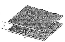
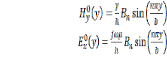
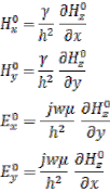
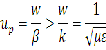
Parallel plate wave guide mainly consist of two perfectly conducting plates separated by a dielectric medium with constituent parameters ε and µ. The plates are assumed to be of infinite length in x-direction as shown in figure.1. Let us suppose that TM waves (Hz=0) propagate in the +z-direction.
2.1 TM waves
Transverse magnetic (TM) wave do not have component of the magnetic field in the direction of propagation hence Hz=0. The behavior of the TM wave can be analyzed using the equation 1.
Fig 1: parallel plate waveguide[3] ![]() [2] (1)
[2] (1)
![]()
The above equation satisfy the boundary condition
We conclude that must be the following form![]()
(2)
Where the amplitude An depends on the strength of the particular TM wave.
(3) (4)
![]()
Propagation constant is given by
Cut off frequency can be obtained by substituting![]()
![]()
fc=
The instantaneous field expressions for TM1 mode are obtained by multiplying equations (2), (3) and (4)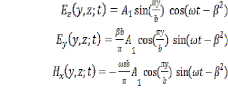
IJSER © 2012
(5) (6)
(7)
The research paper published by IJSER journal is about Mode Patterns of Parallel plates &Rectangular wave guides 2
ISSN 2229-5518
In the yz- plane E has both a y- and a z- component and the relation of the electric field lines at a given time can be obtain from the following equation.
![]() (8)
(8)
Put t=0 in the above equation (8) and which can be rewritten as
![]() (9)
(9)
![]()
Which gives the slope of the electric field lines and integrating above equation we get
Several such electric field lines are shown in the figure (3) Similarly
![]() (10)
(10)
Since H has only an x-component the magnetic field lines are everywhere perpendicular to the yz-plane as shown in Fig 3.
2.2 TE waves[3]
Transverse electric waves, ![]() we solve the following equation for
we solve the following equation for ![]() which is simplified
which is simplified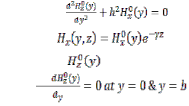
(11)
A rectangular waveguide supports TM and TE modes but not TEM waves. Shape of rectangular waveguide is as shown in Fig 2. A material permittivity e and permeability m fills the inside of the conductor.
In a rectangular waveguide wave propagates below some
frequency called as cut-off frequency. Here, we will discuss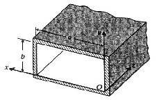
TM wave propagation and TE wave propagation in rectangular waveguides separately. Let’s start with the TM mode.
Fig 2: Rectangular waveguide
3.1 TM waves[3]
Consider the shape of the rectangular waveguide as shown above with dimensions a,b (assume a>b) and the parameters e and m. For TM waves Hz =0 and Ez can be solved from the equation given below
Consider the boundary conditions to be![]()
2xy Ez
0+h2Ez0=0 (16)
satisfied by are obtained![]()
From equation (11) we obtain
(12)
(13)
Since Ez(x, y, z) =Ez0 (x, y) e-gz , we get the following equation, (![]() +
+ ![]() Ez0 (x,y) =0 (16)
Ez0 (x,y) =0 (16)
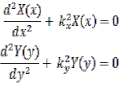
Using the method of separation of variables, that is Ez0
(x,y)=X(x),Y(y) we get,
Where Bn is the amplitude depends on the strength of execution of the particular TE wave,and we can also obtain other non zero field components
(14)
(15)
![]() (18)
(18)
![]()
Since the right side contains x terms only and the left side contains y terms only hence both are equal to a constant. Calling that constant as kx2, we get
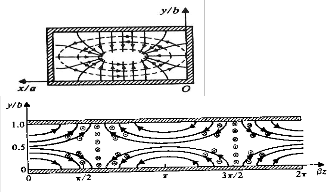
The cut-off frequency for the TEn modes in a parallel plate wave guide is exactly the same as for the TMm mode. For n=0 both Hy and Ex vanish; hence the TE0 mode doesn’t exist in a parallel plate waveguides.
Where =h2-
(19)
(20)
Rectangular waveguides are the one of the type of transmission lines. They are used in many applications such as isolators, detectors, attenuators, couplers and slotted lines and these waveguide components are available for various standard waveguide bands between 1 GHz to above 220
GHz.
Solve for X and Y from the previous equations. Also applying the following boundary conditions,![]()
![]()
IJSER © 2012
The research paper published by IJSER journal is about Mode Patterns of Parallel plates &Rectangular wave guides 3
ISSN 2229-5518
![]()
![]()
From all these, we conclude that
X(x) is in the form of sin kx x, where kx=mp/a, m=1, 2, 3…
Y(y) is in the form of sin ky y, where ky=np/a, n=1,2, 3…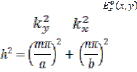
![]() (21) So the solution for is
(21) So the solution for is
From =h2- , we have
Observing the above equations it can be concluded that TM modes in rectangular waveguides will not exist for m or n zero. This is because of the fact that the expressions are identically zero if either m or n is zero. Therefore, the lowest possible values of m and n in a rectangular waveguide are 1 and 1; i.e. TM mode is TM11.
Cut-off wave number and propagation constant is given by
![]() (31)
(31)
![]()
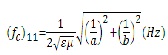
The cut-off frequency is at the point
![]() (32)
(32)
Since l=u/f, we have the cut-off wavelength,
For TM waves, we have![]()
(22) (22)
(33)
![]()
![]()
![]()
From these above equations, we get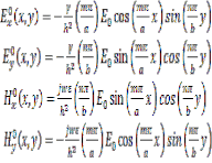
![]()
Where
(23) (24)
(25)
(26) (27) (28) (29)
(30)
At a given operating frequency f, only those frequencies, which satisfy the condition fc <f will propagate.
The mode with the lowest cut-off frequency is called the dominant mode. Similarly modes for rectangular waveguides start from TM11 mode, the dominant frequency
 (34)
(34)
The wave impedance is defined as the ratio of the transverse electric and magnetic fields. Therefore, we get from the expressions for Ex and Hy (see the equations above)
ZTM![]() (35)
(35)
The guide wavelength is defined as the distance
between two equal planes in the waveguide and it’s equal to![]()
![]()
![]()
> = (36)
Where m and n represent possible modes and it is designated as the TMmn .m denotes the number of half cycle variations of the fields in the x-direction and n denotes the number of half cycle variations of the fields in the y-direction.
This is thus greater than I, the wavelength of a plane wave in the filling medium.
IJSER © 2012
The research paper published by IJSER journal is about Mode Patterns of Parallel plates &Rectangular wave guides 4
ISSN 2229-5518
The phase velocity is given by
(37)
![]()
From all these, we get
![]()
at y=b (45)
This is thus greater than the speed of light (plane wave) in the filling material
3.2 TE waves
For TE waves Ez =0 and Hz can be solved from the equation given below
Ñ2xy Hz + h2 Hz=0
Since Hz (x,y,z) = Hz0(x,y)e-gz, the following equation,
![]() (38)
(38)
![]()
Use the method of separation of variables, that is we get,
![]()
From ![]() =h2-
=h2-![]() , we have;
, we have;
![]()
For TE waves, we have
(46)
(47)
(48) (49)
(50)
(51)
![]()
(39)
Since the right side contains x terms only and the left side contains y terms only; hence they are both equal to constant.
2,
From the above equations, we can obtain the following equations.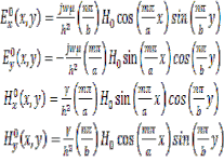
(52)
Calling that constant as kx
we get;
(40)
(53) (54)
![]()
![]()
Where =h2-
(41)
![]()
Where
(55)
Solve for x and y from the preceding equations. Also we have following boundary conditions:
![]() at x=0 (42)
at x=0 (42)
![]() at x=a (43)
at x=a (43)
![]()
at y=0 (44)
(56)
Where m and n represent possible modes and it is shown as the TEmn mode. m denotes the number of half cycle variations of the fields in the x-direction and n the number of half cycle variations of the fields in the y-direction.
Here, the cut-off wave number and propagation is given by
![]() (57)
(57)
IJSER © 2012
The research paper published by IJSER journal is about Mode Patterns of Parallel plates &Rectangular wave guides 5
ISSN 2229-5518
![]() (58)
(58)
The cut-off frequency is given by
![]() (59)
(59)
Since l=u/f, we have the cut-off wavelength,
![]() (60)
(60)
At a given operating frequency f, which have f> fc will propagate. The modes with f<fc will not propagate. The mode with the lowest cut-off frequency is called the dominant mode. Since mode is the minimum possible mode that gives nonzero field expressions for rectangular waveguides, it is the dominant mode of a rectangular waveguide with a>b and dominant frequency is ![]() (61)
(61)
The wave impedance is defined as the ratio of the transverse electric and magnetic fields. Therefore, we get from the expressions for Ex and Hy (refer above equations) ZTE![]() (62)
(62)
The guide wavelength is defined as the distance between two
equal phase planes the waveguide and it’s equal to![]()
![]() >
>![]() = (63)
= (63)
The phase velocity is
 (64)
(64)
This is thus greater than the speed of plane wave in the filling material.
Parallel plate waveguides TM Modes
Fig 3: Field lines for TM1 Mode in parallel plate waveguides
Parallel plate waveguides TE Modes
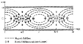
Fig 4: Field lines for TE1 Mode in parallel plate waveguides
![]() Mr.K.chandrashekhar is pursuing his doctoral degree fromVTU,Belgaum,India.e-mail:kcm.shekar@gmail.com
Mr.K.chandrashekhar is pursuing his doctoral degree fromVTU,Belgaum,India.e-mail:kcm.shekar@gmail.com
![]() Dr.Girish V Attimarad is a professor & Head
Dr.Girish V Attimarad is a professor & Head
DSCET,Bangalore,India.e-mail:gattimarad@gmail.com
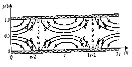
Rectangular waveguide TM modes
Fig 5: Field lines for TM11 Mode in rectangular waveguide
Rectangular waveguide TE10 Mode
IJSER © 2012
The research paper published by IJSER journal is about Mode Patterns of Parallel plates &Rectangular wave guides 6
ISSN 2229-5518
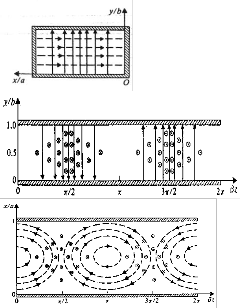
Fig 6: Field lines for TE10 Modes in rectangular waveguide
A rectangular, Circular, elliptical and hollow, Metallic waveguides supports only TE and TM modes but TEM waves don’t exist in a single-conductor hollow wave guide because TEM waves are characterized by Ez=0, Hz=0 and fc=0.
To support all TEM modes for a TEM wave two separate
conductor structure is required, such as Co-axial cable,
Parallel plate waveguide, Strip line and micro strip lines. The two conductor lines can be analyzed in terms of voltage,
current and impedance by the distributed circuit theory. The methodology applied to derive field equations can be extended to other waveguides also. Obtained equations and Computer Simulation results can be compared to understand the field lines and the Propagation characteristics.
REFERENCES
[1] N.Marcuvitz “Waveguide Handbook” The institution of
Electrical Engineers. Dec-1985
[2] David.K.Cheng “Field and Wave Electromagnetics” 2nd
Ed, 2006 Tsinghua University Press pp-520-560
[3] Annapurna Das,Ssir K Das “Microwave Engineering “
Mc-Grawhill HE, Sept 2006.
[4] Constantine A Balanis “Advanced Engineering
IJSER © 2012