The research paper published by IJSER journal is about Mitigation of Torque for Brushless DC Motor: Modeling and Control 1
ISSN 2229-5518
Mitigation of Torque for Brushless DC Motor: Modeling and Control
R.Goutham Govind Raju, S.John Powl, A.Sathishkumar, P.Sivaprakasam
—————————— ——————————
HE brushless DC motor drive system incorporating motors Twith permanent magnet excitations are being used in a rapidly expanding range of applications, including computer peripherals, automotive and machine tool industries. The shaft position sensors, such as Optical or Hall-effect sensors are
usually used to detect exact rotor position.
The Conventional PI Controller (CPIC) is one of the most common approaches for speed control in industrial electrical drives in general, because of its simplicity, and the clear relationship existing between its parameters and the systemresponse specifications. It is also the basis for many advanced control algorithms and strategies. These fixed gains may perform well for some operating conditions but not for all, because the involved processes are in general complex, time variant and non-linearity and model uncertainties.
In fact, PI speed controller’s main drawbacks are load rejection and sturdy to increasing inertia and rotor resistance variations in the case of an indirect rotor flux oriented machine. Moreover, for industrial and process applications requiring high performances, regardless of load disturbances, parameters variations, and any model uncertainties, several self-tuning controllers based on adaptive and optimal control techniques, or artificial intelligent methods, were proposed in order to improve the control robustness. One of the most successful expert system technique applied in a wide range of control applications has been fuzzy logic. It can be combined with conventional PI controller, to build fuzzy tuning controllers, in order to achieve a more robust control. Thefuzzy adaptation can be built via
————————————————
![]() R Goutham Govind Raju is currently Assistant Professor in EEE dept., CK College of Engineering and Technology, Caddalore, Tamilnadu ,India.
R Goutham Govind Raju is currently Assistant Professor in EEE dept., CK College of Engineering and Technology, Caddalore, Tamilnadu ,India.
E-mail: goutham_178@rediffmail.com
![]() S.John Powl is currently Assistant Professor in EEE dept., Sri Manakular
S.John Powl is currently Assistant Professor in EEE dept., Sri Manakular
Vinayakar Engineering College, Puducherry, India.
![]()
E-mail: john_m_83@yahoo.com
A.Sathishkumar is currently Assistant Professor in EEE dept., CK College of
updating fuzzy sets functions, fuzzy rules, or controller gains.
The contribution of this paper is a simple high performance fuzzy tuned PI speed controller of the BLDC motor. The fuzzy rules, used to update the two gains of the PI controller with fixed structure, are based on a qualitative knowledge and experience established from a lot of simulation results of several transient speed responses obtained for different operating conditions such as response to step speed command from standstill, step load torque application, cooling fan.
The brushless DC motor drive system incorporating motors with permanent magnet epxcitations are being used in a rapidly expanding range of applications, including computer peripherals, automotive and machine tool industries. The shaft position sensors, such as Optical or Hall-effect sensors are usually used to detect exact rotor position.
The brushless DC motor has trapezoidal Electro Motive Force (EMF) and quasi-rectangular current waveforms. Three Hall Effect sensors are usually used for every 60 degree electrical (Jardic. M and Teric. B 2001). In addition to servo drive application with high stationary accuracy of speed and rotor position, the brushless DC motor requires a rotor position sensor, such as a revolver or an absolute encoder.
Recently, DC motors have been gradually replaced by the BLDC motors as industrial applications require more powerful actuators in small sizes. Elimination of brushes and commentators also solves the problem associated with contacts and gives improved reliability and enhances life. The BLDC motor has low inertia, large power to volume ratio, and low noise when compared to the permanent magnet DC servo motor having the same output rating.
This paper comprises of III section, the first section
consisting of Modeling of PMBLDC and its operation is then![]()
Engineering and Technology, Caddalore, Tamilnadu ,India.
IJSER © 2012
P.Sivaprakasam is currently Assistant Professor in EEE dept., Sri Manakhuttpla:/r/www.ijser.org
Vinayakar Engineering College, Puducherry, India.
The research paper published by IJSER journal is about Mitigation of Torque for Brushless DC Motor: Modeling and Control 2
ISSN 2229-5518
followed by section II simulation results, finally the paper id concluded
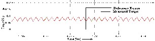
The Brushless DC motor is also referred to as an electronically commuted motor. There are no brushes on the rotor and the commutation is performed electronically at certain rotor positions. The stator magnetic circuit is usually made from magnetic steel sheets. The stator phase windings are inserted in the slots or it can be wound as one coil on the magnetic pole. The magnetization of the permanent magnets and their displacement on the rotor are chosen such a way that the Back- EMF shape is trapezoidal as shown in
Figure 3.1. This allows the three phase voltage system, with a rectangular shape to be used to create a rotational field with low torque ripples.
The conducting interval for each phase is 120o electrical angle. The commutation phase sequence is like AB-AC-BC-BA- CA-CB, where A, B, C are the three phases. Each conducting stage is called one step. Therefore, only two phases conduct current at any time, leaving the third phase floating. In order to produce maximum torque, the inverter should be commutated every 60o, so current is in phase with the back EMF. The commutation timing is determined by the rotor position, which can be detected by position sensors. When a BLDC motor rotates, each winding generates a voltage known as back Electromotive Force or back EMF, which opposes the main voltage supplied to the windings according to Lenz’s Law. The polarity of this back EMF is in opposite direction of the energized voltage. Back EMF depends mainly on three factors (a) Angular velocity of the rotor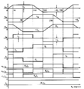
, (b) Magnetic field generated by rotor magnets and (c) The number of turns in the stator windings.
Fig.3.1: PM Brushless DC Motor waveforms
The BLDC motor is controlled by the three different modes, the torque ripples are mitigated by fuzzy controller, neural controller and hybrid controller.
The overall block diagram of the controller designed for minimizing the torque ripple of a BLDC motor is shown in Figure 3.2
The two gains of the PI controller will be initialized using well-known conventional methods, but these gains depend on the BLDC motor estimated model at rated operating conditions. Fuzzy logic control (FLC) has been found to be excellent in dealing with systems that are imprecise, non-linear, or time- varying. FLC is relatively easy to implement, since it does not need any mathematical model of the controlled system. This is achieved by converting the linguistic control strategy of human experience and knowledge into an automatic control strategy.
On-line tuning of controller becomes of interest, since it is
very difficult for off-line tuning algorithms to deal with the continuous variations in the BLDC motor parameters and the non-linearity’s present in the inverter, motor and/or controller. The most important parameters of Fuzzy logic are scaling factors. The input scaling factors affect the FLC sensitivity while the output scaling factors affect the system stability.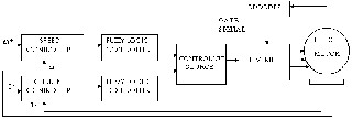
Fig 3.2: Overall Block Diagram of the BLDC Motor Drive
The block diagram of Brushless DC (BLDC) motor using ANNs is presented in the Figure 3.3, where Neural Network Speed controller used to estimate the speed and Neural Network Current controller are trained to control terminal voltage. In a supervised off-line control, the proposed original PI based controller can be replaced by a neural network that learns the mapping form of the controller input-output relationship by adapting its parameters to a training set of examples of what it should do.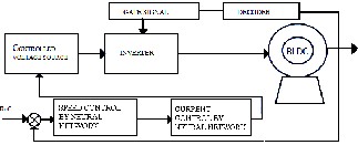
Fig 3.3: Block Diagram of BLDC Motor Using Neural Network
Controller
IJSER © 2012 http://www.ijser.org
The research paper published by IJSER journal is about Mitigation of Torque for Brushless DC Motor: Modeling and Control 3
ISSN 2229-5518
The BLDC Model drive with speed and current controllers has been simulated in MATLAB/Simulink model. The torque ripple minimization graphs for a various step changes in load torque are shown in figures. The model of the brushless DC motor drive system is simulated to investigate its dynamic performance and simulated results are shown.
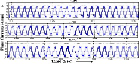
The motor phase currents, back EMFs and pulses to the inverter are shown in Figure 4.1 (a), (b), and (c).
(a)
(b)
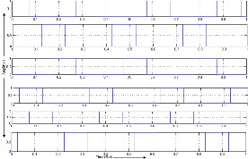
Fig 4.1: (a) Motor Phase Currents, (b) Motor Back EMFs, (c) Inverter
Pulses
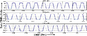
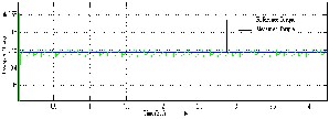
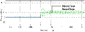
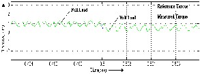
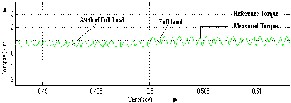
The Torque Ripple with PI Controller and Fuzzy logic controller under Half Load, Full Load, and No Load are shown in Figure 4.2 (a), (b), (c) and 4.3 (a), (b) resp. The Figure 4.3 shows the membership function of fuzzy logic control, the Tabular column 4.1 shows the rule based of fuzzy logic control.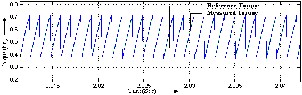
(a)
(b)
(c)
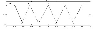
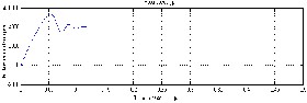
Fig 4.2: Torque Ripple with PI Controller under (a) Half Load, (b) Full Load, (c) No Load
Input Variable (Error)
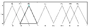
Input Variable (Change in Error)
Output Variable
Fig 4.3: The Membership function for
TABLE 4.1
![]()
FUZZY RULE BASE
i ω | NB | NS | ZE | PS | PB |
NB | NB | NB | NM | NM | ZE |
NS | NM | NS | NS | NS | PS |
ZE | NS | ZE | ZE | ZE | PS |
PS | NS | PS | PS | PS | PM |
PB | ZE | PS | PM | PM | PB |
(a)
IJSER © 2012 http://www.ijser.org
The research paper published by IJSER journal is about Mitigation of Torque for Brushless DC Motor: Modeling and Control 4
ISSN 2229-5518
(b)
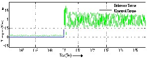
Fig 4.3: Torque Ripple with Fuzzy Controller under (a) Half Load, (b) Full
Load
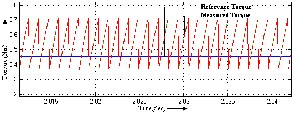
The torque ripple minimization graphs for ANN controller for a various step changes in load torque are shown in Figures 4.4 (a), (b), (c).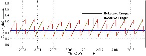
(a)
(b)

(c)
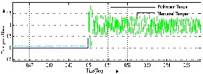
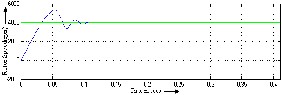
Fig 4.4: Torque Ripple with ANN Controller under (a) Half Load, (b) Full
Load, (c) No Load
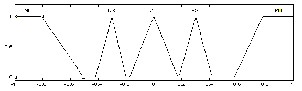
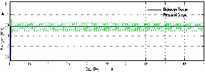
The BLDC Model drive with speed and current controllers has been simulated in MATLAB/Simulink model. The Torque Ripple with Hybrid and ANFIS Controller from for full load to half Load, 3/4th Load to Full Load and for Various Loads are show in Figure 4.5 and 4.6 (a), (b), (c) resp.
(a)
(b)
(c)
(d)
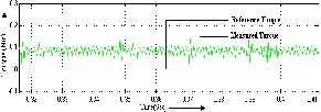
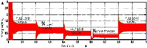
Fig 4.5: Torque Ripple with Hybrid Controller under (a) Half Load, (b) Full Load, (c) 3/4th Load, (d) No Load under rated speed
The Figure 4.7 and 4.8 (a), (b), (c) shows the Torque Ripple with Hybrid controller for full Load to half load, 3/4th loads to full load and various loads under rated speed.
(a)
(b)
(c)
Fig 4.7: Torque Ripple with Hybrid Controller from
(a) Full Load to Half Load, (b) 3/4th Loads to Full Load, (c) Various Loads under rated speed
IJSER © 2012 http://www.ijser.org
The research paper published by IJSER journal is about Mitigation of Torque for Brushless DC Motor: Modeling and Control 5
ISSN 2229-5518
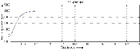
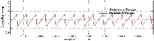
The speed of rotor of BLDC motor Speed Response at Full Load using PI Controller, Fuzzy Controller, and Hybrid Controller is shown in Figure 4.6 (a), (b), (c).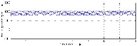
(a) (b) (c)
(d)
Fig 4. 6: Speed Response at Full Load using (a) PI Controller, (b) Fuzzy Controller, (c) Hybrid Controller (d) ANN Controller
The following tabular column 4.2 shows the amount of torque ripple under various loads for rated condition.
TABLE 4.2
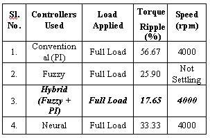
OVERALL COMPARISONS OF DIFFERENT CONTROLLER
The performance analysis of 0.5 hp Brushless DC motor is simulated through Matlab/Simulink. The Stator current and the motor back EMFs are discussed under rated condition. The
pulses to the inverter are also discussed. The torque generated by BLDC motor usually has more ripples in nature which leads to speed fluctuation, vibration and acoustic noise. Hence, the methods to minimize the ripple in torque are also discussed by using suitable controller (Conventional & Non-conventional) method. Comparative analysis of different techniques is also done.
[1]. H.Le-Huy, P.Perret, and R.Feuillet, “Minimization of torque ripple in brushless dc motor drives”, IEEE Trans.Ind.Appl., Vol. IA-22, no.4, pp.748-755, Jul./Aug.1986.
[2]. H.Zeroug, B.Boukais, and H.Sahraoui, “Analysis of Torque Ripple in
a Brushless DC Motor”, IEEE Transs on magnetics, Vol.38, No.2, March 2002.
[3]. Haifeng Lu, Lei Zhang and Wenlong Qu “A New Torque Control Method for Torque Ripple Minimization of BLDC motors with un- ideal back EMF” – IEEE Transaction on power electronics, Vol., 23, No.2, March 2008
[4]. Sung Jun Park, Han Woong park, man Hyung Lee and Fumio
Harashima “A New Approach for Minimum Torque Ripple Maximum Efficiency Control of BLDC motor”- IEEE Transaction on Industrial electronics, Vol.,47, No.1, February 2000.
[5]. Zhang Xiaofeng and Lu Zhengyu “A new BLDC motor drives method based on BUCK converter for torque ripple reduction” – IEEE Transaction 2006.
[6]. Wei Chen and Changliang Xia, “Sensorless Control of Brushless DC Motor Based on Fuzzy Logic”, Trans.Ind.Appl, 2006
[7]. Byoung-Hee Kang, Choel-ju Kim,Hyung-Su Mok and Gyu-Ha Choe,
“Analysis of Torque Ripple in BLDC motor with commutation time,” Proceedings of IEEE,Vol.25,pp.1044-1048, June 2001.
[8]. CarlsonR,Lajoie-Mazenc M and Fagundes J.C.d.S., “Analysis of torque ripple due to phase commutation in brushless DC machines,” IEEE Trans. On Industry Applications, Vol.28, no.3, pp.632-638, May-June 1992.
[9]. C.L.Xia,J.Wang, T.N.Shi, and S.H.Xu, ”A novel method for torque ripple minimization of the Sensorless brushless DC motor,” Journal of Tianjin University, Vol. 38, no. 5, pp. 432-436, May 2005.
[10]. Ki-Yong Nam, Woo-Taik Lee, Choon-Man Lee, and Jung-Pyo Hong,”Reducing Torque Ripple of Brushless DC Motor by Varying Input Voltage,” IEEE Transcations on Magnetics, Vol. 42, No.4, April 2006.
[11]. J-G.Lee, C.S.Park, J.-J.Lee, G.H.Lee, H.-I.Cho, and J.-P.Hong, “Characteristic analysis of brushless motor condering drive type,”KIEE, pp. 589-591, Jul.2002.
[12]. D.Hanselman, J.Y. Humg, and M.Keshura, “Torque Ripple analysis in brushless DC motor drive,” in Proc. ICEM’92, Manchester, U.K., Sept.,pp.823-827.
[13]. J.Y.Hung and Z.Ding, “Design of currents to reduce torque ripple in brushless permanent magnet motors,”in Proc.IEEE, Jul.1993, vol.140, pp.260-266, no.4
IJSER © 2012 http://www.ijser.org