INTRODUCTION
A
pre-assigned sequential shutters opening and closing control is a requirement for any astronomical observato- ry-dome intended for sky watching with optical tele-
scope. Opening and closing of the viewing window of SirusMaxDome II observatory dome [1] is controlled through sequential movement of electromechanical relay feedback con- trolled, dc motorized heavy shutters.
Sirus MaxDome II (Fig.1a & Fig.1b) is a standard hemispher- ic observatory-dome having viewing window opening facility measuring half length of semi perimeter along right vertical plane passing through the centre of the dome facing the sky. It has two shutters to open the viewing window. Two separate dc motors driving those shutters. Movementsof one sliding- shutter (shutter1) and another flipping shutter(shutter2)in particular opposite sequence complete the opening and clos- ing of the viewing window.
In MaxDome II observatory dome, movement of sliding- shutter has been accomplished by a rack-pinion arrangement. To achieve sufficient reduction in transmission of motion, a worm gear is firmly attached to the rotor of a dc motor for pinion to drive the rack. A quarter circular shaped rack (of the Rack-pinion) is firmly attached to the sliding-shutter to be driven by the pinion. There are two normally closed (NC) stat- ic limit switches namely 1_C and 1_O (Fig.7) fixed suitably elsewhere to the static dome framework. The bi-toggle states of those mechanical limit switches enable two feedback con- trol lines namely C & D (Fig.2, Fig.5 & Fig.6) to monitor posi- tional extremities of the sliding-shutter while on move.
Similarly, movement of theflipping-shutter has been ac- complished by a lead-screw arrangement. A rotating lead screw is attached to the rotor of another dc motor and the cor- responding linear-actuation-lever is attached to the framework of the flipping-shutter. The flipping-shutter is hinged at the diametric circular horizontal plane of the dome such that to
open the viewing window, the shutter flips outside the dome about the hinge in downward direction. There are also another set oftwo normally closed static limit switches namely 2_C and 2_O (Fig.7) suitably attached elsewhere to the dome framework to enable another two feedback control lines name- ly E & F (Fig.2, Fig.5 & Fig.6) to monitor positional extremities of the flipping-shutter in the course of above flip movement. According to design of the Sirus MaxDome II observatory dome with two shutters, it is a must to maintain a particular opposite sequence in shutters movement to open/close the viewing window for the telescope to watch sky.
For opening the viewing window of the MaxDome II ob- serva-tory dome with two shutters, sliding-shutter is arranged to opens first followed by flipping-shutter. For closing the viewing window, flipping-shutter hasto close first then the sliding-shutter. Hence the movement of shutters sequence is first opening-last closing (FOLC) and last opening first closing (LOFC).

Fig.1a. MeghnadSaha Observatory, Kolkata.
————————————————
Shaibal Saha is a Technical staff member and presently designated as Scien- tific Officer-C in Applied Nuclear Physics Division of Saha Institute of Nuclear Physics, Department of Atomic Energy, Govt. of India,
PH-913323375345 Ext.3406.
E-mail: shaibal.saha@saha.ac.in
But, here lie the tricks of the logic circuit design to ensure turning on and off the corresponding motor powerlines dy- namically while shutters are parked at either opening or clos- ing extremity positions. In addition, designer has to ensure shutters closing logic states along with 12V powerline are to
IJSER © 2013
be ready while viewing window is just fully open conditionso that upon toggling the single logic state to close option, shut- ters will start moving sequentially in closing direction of the viewing window. Similarly, designer has to meet another most important condition that is upon fully closing of the viewing window at the end of one session and switching off the 12V main battery power thereon, the closing states of those four positional limit switches will become at shutter opening logic states as soon as 12V battery power is switch on once again for the next session. So, initialization of digital logic control states is ensured upon switching on the 12V main power supply for subsequent session to follow FOLC-LOFC logic.
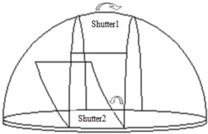
Fig.1b. Sirus MaxDome II Schematic.
Therefore, upon initiation of step 2 (Fig.2) either locally or remotely through TCP/IP or GPIB etc. steps 3 to 6 will execute one after another nonstop and automatically to open both the shutters in pre assigned sequence. Again, at fully open state of the viewing window, similar single initiation of step 7 triggers closing sequence of shutters through steps 8 to 11. Remaining steps 12 & 1 are reserved for 12V standby battery power state at fully open window condition with maximum ~265 mA steady drain current (Fig. 8) and for battery power switch tog- gle state at fully closed window condition (Fig.2). This is ac- complished with a tri-state manual toggle switch and instead that also can be remotely controlled by two logic control lines namely A & B (Fig.2) as future provision.
Now, it is comprehendible that with judicious routing (Fig.7) of 12V motor power through limit switches, sequential
as follows.
DESIGN APPROACH
Generation of Feedback Control Lines


Now, to derive exact TTL control pulses with proper driving fan-out and also for mechanical switch de-bouncing due to damped oscillation at electromechanical contacts, a Schmitt trigger is introduced in betweento negotiate [2]. Now we have C, D, E, and F four standard TTL feedback control ports. The TTL logic states of these ports indicating the positional ex- tremities movement steps of both the shutters in terms of elec- trical signals. We need another two ports to initiate Open/Close options of the shutters. A SPST tri stable toggle switch is in- troduced to generate two ports as A and B. All these six ports are passed through a TTL hex inverter to get correspond- ing A, B, C , D, E & F .
Formation of Boolean Equations
Now we have four feedback control lines i.e. C, D, E & F and two trigger lines i.e. A & B as six variable input to derive two feedback control outputs. TheTruth Table (Fig.2) shown below for sequential logical outputs for relay control lines
 &
& .
.
Fig.2. Truth Table
Then, following are two Boolean equations (1) & (2) for cor- responding relays to feed power to sliding-shutter and flip- ping-shutter driving dc motors [3].


operation of shutters movement described in the foregoing
paragraphs can easily be achieved. But, had the motor drives are to handle much higher voltage andhigh current switching

X out = ABCDE F + ABCDE F + ABC DE F + ABC DEF
+ ABC DEF + ABC DEF + ABC DEF + ABC DEF
(1)


to open/close the viewing window, direct high voltage and
high current switching at the manual control panel would not be a safer design.
On the other hand, any high voltage and high power elec- trical system cannot be controlled remotely through suitable
Yout = ABC DE F + ABC DEF + ABC DEF + ABC DEF
Karnough Map Reduction
(2)
computer software programming unless a digital logic inter- face is introduced in between. Thus, necessity of low voltage digital control hardware interface comes into picture.
Applying 6-variables Karnough Map reduction (Fig.3 & Fig.4)
as sum of products to both the above two Boolean equations
we can get Boolean Equation 3 & Equation 4 below [3],[4],[5].


Therefore, to be on the safe side, as well as incorporating an
option for remote computer control, a low power control of
X out = ABDEF + ABC DF + BC DEF + ABC DE
(3)

hazardous high power implies a digital electronic logic control
of the MaxDome II observatory dome shutters control system
Yout = ABC DF + BC DEF
(4)
IJSER © 2013
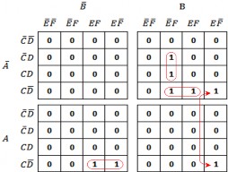
Fig.3. Karnough Map for Xout
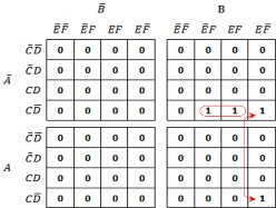
Fig.4. Karnough Map for Yout
In the truth table (Fig.2) four inputs feedback control lines C, D, E and F derived from four limit switches actuate auto- matically according to shutters movement except control lines A and B which are triggered manually by the users through open/close tri-state toggle switch.
Logic Gate Circuit as Sum of Products
Following logic gate circuit diagram (Fig.5) shows as sum of products derived from the reduced Boolean equations (3) &
IJS
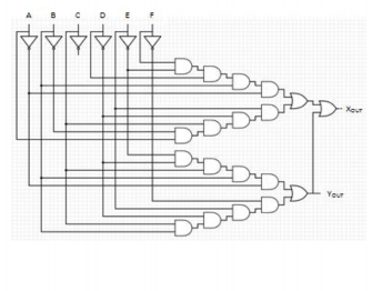
(4) for feed back control lines
 &
&  [3],[4],[5].
Fig.5. Sum of products logic gate circuit
Mode of Operation
Initially, both shutter1 and shutter2 are closed, control switch for triggering open/close is at neutral position putting A, B both high and 12Vmain battery power switch is off. In this state, limit switches, 1_O of shutter1 and 2_O of shutter2 are closed and corresponding other limit switches, 1_C and 2_C are open.The feedback control lines C, D, E & F (Fig.6) are drawn from 1_C, 1_O, 2_C & 2_O respectively (Fig. 7).
When both shutter1 and shutter2 are closed, turning on 12V battery power initializes feedback control lines C and E at low and lines D and F high (Fig.6). Now a low trigger to A and B remaining high causes 12V main battery power starts opening shutter1 through forward rotation of corresponding motor, M1.
Fig.6. Logic Control Timing Diagram
Immediately, shutter1 connects limit switch 1_C putting line C high. At the open extremity, shutter1 actuates on limit switch 1_O to put line D low. This low D causes shutter to stop movement and shutter2 to start opening. Immediately shutter2 connects limit switch 2_C putting line E high. Similar- ly at the open extremity, shutter2 actuates on limit switch 2_O and thus line F goes to low thereby stopping shutter2. Now, viewing window of the dome is open for sky watching. In this state both the shutters are parked at fully open condition and two commutation relays draw a constant drain current
~259mA (Fig.8) due to their energized states.
Now, putting simultaneously control line A high and con-
trol line B low, causes reverse power to the shutter2 motor
thereby shutter2 starts closing. In the closing movement, shut-
ter2 first actuates limit switch 2_O causing line F high and at
the closing extremity actuates limit switch 2_C thus putting
line E low. This automatically initiates shutter1 to start closing.
Finally upon closing both the shutters, initial states of feed-
back control lines are restored. Now, either the main 12V bat-
tery power can be switched off or can be go ahead for a new
viewing window opening session [6],[7],[8].
Commutation for Motor Rotation
In MaxDome II observatory dome, two separate 12V dc motors are used and we require reversal of direction of current to do with change in direction of the rotor shaft as well as shutters for opening and closing. So, two double-pole & double- through (DPDT) electromechanical relays having suitable am-
ER © 2013
perage are placed to facilitate commutation of motor current at suitable logical instances (Fig.7).
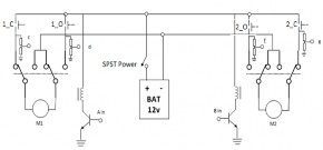
Fig.7. Motor drive circuit diagram
Logic Family Selection
What one should consider in selecting logic family are reliabil- ity in this adverse ambient conditions, contemporary genera- tions in production line to cope with future availability, low power devices for prolonged battery operation, fast enough and capable of driving directly Si-NPN transistor for actuating relay coil as well as higher fans out for multiple logic gate drive and compatible with other logic families.
Those Xoutand Youtdigital outputs are intended to control the shutters controlling 12V dc motors. It can be achieved
through 12V electromechanical relay contacts drive for han- dling motors current at least up to 3.5A and more. We know logic levels VOL =0.5V and VOH =2.4V is very much suitable for direct driving Silicon NPN transistors. So, TIP122, a Si-NPN, Darlington transistor of β=1000 is very much suitable for 12V relay coil drive at 120mA load current for relay coil. But, a low power digital gate circuit is best suited for prolonged battery operation. Therefore, a cutting age, low-power, high speed and high fans out suggests selection of 74ACT glue logic fami- ly [9] for the gate control circuits. It has wide supply voltage (5.0±10%) range and shows the reliability in operation over
ambiance temperature range (-40 to 85 ⁰C). This is extremely
necessary at high ambience tropical zones. Moreover, 74ACT
family exhibits better immunity to electromagnetic noise.
Above all this low power advance CMOS technology family
will be available in the market for at least another decade to
support the system over mostly obsolete TTL, 74LS etc. fami-
lies. Thus cutting age 74ACT family logic gates are selected for
this control circuit.
Relay Coil Driver
Here, each relay coil draws ~120mA current at 12V to actuate. 74ACT family glue logicgates (±24mA of IOH and IOL) are unable to drive such a load current. Therefore, Si-NPN TIP122 Darlington stages are introduced to do with appropriate cur- rent gain to buffer each Xout and Yout for driving two separate relay coils. Xout and Youtat active high state energize corre- sponding relay coil to enable commutation at proper logic in- stances. Thus, change in direction of rotation of motor shaft helps to achieve direction of shutters movement accordingly. To protect the relay driving transistors from back EMF pro- duced by the inductive load switching, a snubberdiode protec- tion circuitry with 1N4007 diode has been used for both the
relay coils.
Battery Energy Storage Consideration
Change in battery load current (Fig.8) shows that digital gate circuit drawing 19mA steady current upon power on. Thereby a trigger “open” starts opening the shutter1 through shutter2 and halts at a steady state drain current of 259mA during the viewing window is open at steady state. The whole automated opening phase (step 3 to 5) takes maximum 60 seconds. Simi- larly, upon triggering “close”, the whole automated closing episode (step 6 to 8) takes atmostanother 60 seconds. The above two phases takes steady state logic gates current of
~19mA, relay coil current @120mA for each of the relays and 2.0A to 3.5A varying motor drive current (Fig.8) for each mo- tor. Though these two phases are the maximum current draw- ing phases, duration is limited to maximum 120 seconds alto- gether. But, the opened window phase, indicated in phase 5 (Fig.8), is the longest phase and may take whole night, i.e. the sky watching hour. So, in this phase battery drain current is a matter of concern and fortunately in this phase the steady state current goes down to 259mA. It comprises only ~19ma for control circuit and @120mA for each relay coil. Therefore, 120 seconds dynamic, high current phases consume maximum 0.5Ah battery energy and steady sky watching period will consume @ 0.26Ah/hour battery energy.
Fig.8. Changes in Battery Load Current
There is a 26Ah, 12v solar recharge battery backup connect- ed to the control system. This implies a fully charged battery can provide power to the ideal system for 98.07 hours nonstop until fully exhausted. But, fortunately in Kolkata (22°34′10.92″N and 88°22′10.92″E), considering seasonal varia- tions, within maximum 14 hoursnight time, sunlight will re- appear to recharge the battery through solar power charging unit. So, the system is well designed for uninterrupted watch- ing the sky overnight and no shortfall of power due to over- night no charging period. Battery regains its charge during day time when no sky watching activity as well no window opening operation comes into picture by virtue.
As MaxDome II observatory dome with two shutters re- quires standalone control in opening /closing of viewing win- dow with the help of only sequential movement of shutters, this control (Fig.9) no way requires software options. So, for fast and flawless movement a hardware implementation is the best option. Only 12v dc power switch on/off operation and
open/close toggle switch operation are left available on the control panel.
DISCUSSION
Instead of relay commutation, use of H-bridge is the most popular and standard method of controlling dc motor either for speed or direction as well. A pulse width modulated (PWM) signal-driven dc motor commutated through standard intrgrated circuit H-bridge (IC H-bridge) is one step ahead of this design and a photosensing device can be used as limit switch [10].

Fig.9. Shutters control circuit
FUTURE PLAN
TCP/IP Protocol
These two switches may suitably be controlled over TCP/IP protocol. The above hardware can easily be controlled through Ethernets using standard TCP/IP control relays. In that case only A and B inputs controlling relays are required. Thus a hardware controlled through a minimal software script averts writing lengthy programming, debugging and ensures faster, full proof operation.
Control through customized GUI
CONCLUSION
The above digital logic gate controlled electronic circuit (Fig.9) to control the sequential movement of two shutters of Max- Dome II observatory has been implemented at MeghnadSaha Observatory (Fig.1a) at Saha Institute of Nuclear Physics (SINP), Kolkata (22°34′10.92″N and 88°22′10.92″E). We found all the logic control lines working faithfully over time. Both
the motors and the logic circuit drawing current as calculated. So the 12V main solar recharged captive battery power with 26Ah energy storage suitably supportive to the system.