
International Journal of Scientific & Engineering Research, Volume 5, Issue 7, July-2014 1
ISSN 2229-5518
Microcontroller ATmega32 Based Automatic
Vehicle Control
Abstract— This paper proposes novel control architecture for automatic vehicle driving in a dynamic and uncertain traffic environment.In the present scenario accidents are increasing rapidly. We need to make such a system which can continuously detect obstacle around the vehicle and avoid them from collision. We choose ATmega32 microcontroller for the controlling of the system.The implemented design will increase the safety and reliability with reducing the risks of life.
Keywords—ATmega 32 microcontroller, Counters, crystal oscillator, IR transmitter, IR receiver.
—————————— ——————————
Microcontroller Based vehicle is a field of application of auto- mation, which is a modern technology in automobile sector. The 1960's research has generally been focused on software control vehicle. Scientists from Europe and America both be- gan work on autonomous vehicles as an area of application of robotics. These projects have been created from passenger- sized vehicles, as well as small model vehicle [1], [2].
A 56 kHz signal is generated by a microcontroller program. ATmega32 flash microcontroller has been used which having
40 pins . It has 32digital Input & out put port, of which just 7
pins have been used in this project.This microcontroller pro- gram is loaded on the 40 pin microcontroller ATmega 32. The vehaicle avoids obstacles which it senses with its active infra- red sensors. The IR LED will emit infrared. The sensor is built with infrared LED which runs at a speed of 56 kHz. When the infrared light from the LED is reflected by an object the IR re- ceiver senses this.
————————————————
• Md.Abul Hossain has completed her B.Sc. degree from Chittagong University
of Engineering and Technology and is currently working as Infrastructure
Power Engineer in Orascom Telecon Limited. PH: +8801939900447. E-mail:
shabuddin01@yahoo.com
The output from this receiver which is a square wave is the input of the 555 timer. The output of the 555 timer from the pin no- 3 of ATmega32 is fed to the base of the transistor though a resistor and capacitor. The capacitor 1000 µF which is used here makes the high output of the 555 timer a constant line which is always high. The motor winding is connected to the transitor by 8V supply. In this way the vehicle takes the decision when it finds a obstacle.
1. To detect existence of any object in left front of the car by infrared sensors by using radar and doppler principle.
2. To detect existence of any obstacle in front of the vehicle by infrared sensors.
3. Construct a vehicle which can make Primary decesion before collision.
4. Controlling the vehicle with the front two wheels by two individual dc motor according to the position of obstacle or any vehicle.
5. By the input of 56 kHz signal from the microcontroller sensors detect the position of obstacle or vehicle then take the decision whether turn or not and fed the signal to the receiver TSOP1356 to take the decesion about avoiding
obstacle or vehicle by reversing one of the dc motors.
IJSER © 2014 http://www.ijser.org
International Journal of Scientific & Engineering Research, Volume 5, Issue 7, July-2014 2
ISSN 2229-5518
Fig 1 Block diagram of the project
IR-LED is a one kind of led which emittes infrared light like normal light emitting diode.As like other led it also has two terminal.The large pin is anode and the smaller pin is cath- ode.It emittes infrared light and reflect the light on any sub- stance same as the principle of visible light.
DATA SHEET OF THE IR TRANSMITTER:
Order No. | Lens Color | Wave lenght (nm) | Electro–optical characteristics | ||
Order No. | Lens Color | Wave lenght (nm) | Vf(V) | le (mW/sr) | |
Order No. | Lens Color | Wave lenght (nm) | Typ. | Max. | le (mW/sr) |
Dark Blue Transparent | 850 | 1.5 | 1.8 | 160 mW/sr @ 50mA | |
Dark Blue Transparent | 850 | 1.5 | 1.8 | 80 mW/sr @ 50mA | |
Water Clear | 940 | 1.2 | 1.6 | 30 mW/sr @ 10mA |
3.2. IR RECEIVER
The TSOP1356 is miniaturized receivers for infrared remote control systems. PIN diode and preamplifier are assembled on lead frame, the epoxy package is designed as IR filter The de- modulated output signal can directly be decoded by a micro-
processor.
TSOP1356 is the standard IR remote control receiver series, supporting all major transmission code.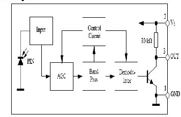
Fig 2 IR receiver
4 ATmega32 MICROCONTROLLER
• High-performance, Low-power AVR 8-bit Microcontroller
• Advanced RISC Architecture
– 131 Powerful Instructions – Most Single-clock Cycle Execu-
tion
– 32 x 8 General Purpose Working Registers
– Fully Static Operation
– Up to 16 MIPS Throughput at 16 MHz
• Nonvolatile Program and Data Memories
– 16K Bytes of In-System Self-Programmable Flash
Endurance: 10,000 Write/Erase Cycles
– 512 Bytes EEPROM
Endurance: 100,000 Write/Erase Cycles
– 1K Byte Internal SRAM.
– Programming Lock for Software Security.
• Peripheral Features
– Two 8-bit Timer/Counters with Separate Prescalers and
Compare Modes.
– One 16-bit Timer/Counter with Separate Prescaler, Compare
Mode and Capture mode.
• Speed Grades
– 0 - 8 MHz for ATmega16L
– 0 - 16 MHz for ATmega16
• I/O and Packages
– 32 Programmable I/O Lines
• Operating Voltages
– 2.7 - 5.5V for ATmega16L
– 4.5 - 5.5V for ATmega16
IJSER © 2014 http://www.ijser.org
International Journal of Scientific & Engineering Research, Volume 5, Issue 7, July-2014 3
ISSN 2229-5518
This is the project of Microcontroller based automatic guided vehicle to overcome accident. All system of this project done by microcontroller interfacing with DC motor, IR sensor & other electronics parts. The complete circuit diagram for con- trol circuit of this project is given below:
Fig 3 Complete circuit diagram of the project
Fig 4 Transmitter Circuit
In this project IR LED have been used as transmitter. The transmitter circuit is supplied by a 8vdc supply and an 8 MHZ clock signal. The 8vDC supply is regulated to 5 v dc supply by a regulator. This 5 vdc supply is fed to the 10 no pin of AT mega 32 which is the Vcc supply of AT mega 32. There is a crystal oscillator connected in between pin no 12 and 13. There is two 22pF capacitors connected in parallel with the crystal. Second pin of port B (PB2) is used as output port of ATmega32 which is connected with two resistances of 22k and 10k. The microcontroller has been programmed to generate 56 kHz square wave. This square wave input is fed to the base of an npn transistor BC436. The amplified signal from the transistor is transmitted by the IR LED.
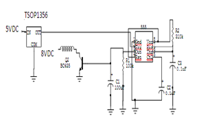
Fig 5 Receiver Circuit
The reflected signal is received by the receiver TSOP1356. The receiver is supplied by 5 vdc. The receiver generates square wave output. This output is fed to 2 no pin
of 555 timer[7]. 555 timer is used to generate one shot.
when a timer is operated as a one shot multivibrator , the o/p voltage is low until a negative going trigger pulse is applied to the timer, then the o/p switches high. The time the output is high is determined by a R and C connected to the 555 timer. The value of rasistance is 310kohm and the value of capacitor is .1µF. The output of 555 timer is fed to the base of the transis- tor BC435. Its collector is connected to motor winding. This winding is supplied by 8vdc. The 1000µF capacitor smoothens
the output.
IJSER © 2014 http://www.ijser.org
International Journal of Scientific & Engineering Research, Volume 5, Issue 7, July-2014 4
ISSN 2229-5518
$Device= m32
$Stack = 32
$Clock = 8
DDRB=1
Dim a As Word
Do
For a=0 To 30
PORTB.2=1
Nop 65
PORTB.2=0
Nop 65
In this project infrared sensor is used to detect obstacle nearer the vehicle about 1ft. But when this concept developed in large vehicle then high range sensor or high-resolution camera is used [9]. Image processing software may be used to identify the obstacle. For understand low and high distance obstacle receiver module will be developed and send data quickly in the control unit to control the vehicle. So it will be most bene- ficial technology now a day.
A. The number of Transmitter & Receiver (sensor)
should be more for flexible operation.
Next
WaitMs 10
Loop
A. For turning left or right, the car should be move with the angle 500 respectively,but it moves approximately
300
B. DC motor’s RPM is slightly low due to weight of the car instrument
C. With appropiate frequency adjust between transmit- ter & receiver the sensors work properly.But it is quite hard because it vary with supply voltage
D. Supply voltage must be between “3.6V to 5V” other
wise biasing problem & frequency problem occurred that is why we could not provide the circuit greater than 5 volt & it is thus it is impossible to speed up or increase the RPM of the DC motor.
E. The current rating of the battery available in the mar-
ket is very low. But in order to run the vehicle the current rating must be high. So it requires a lot of ad- justments to increase current rating.
B. If high range sensor is used, it can easy to detect the long distance object.
C. For control the vehicle efficiently, programe of micro- controller also be updated requirement.
D. Image processing software may be used for identify the obstacle.
[1]Engr. Lawrence Oborkhale,Microprcessor and Applications
Lecture Notes.
[2]Engr.Balogun,Semiconductor Devices Lecture Notes. [3]http://www.acces-automation.co.uk
[4] http://www.gateautomation.com [5]S.A.Nasar,I.Boldea,Electric Drives(CRC/Taylor and Fran- cis,2006)
[6]V.Subramanyam,Electric Drives(Mc-Graw Hill,1996) [7]Edwin Wise,Robotics Demystified(Mc-Graw Hill,2005) [8]http://nidm.gov.in/idmc2/PDF/Presentation/road- accidents/Press4.pdf [9]V.Milanès,C.González,J.Naranjo,E.Onieva,T.De Ped- ro”Electro-hydraulicbraking system for autonomous vehi-
cles”,nternational Journal of Automotive Tech-
IJSER © 2014 http://www.ijser.org
International Journal of Scientific & Engineering Research, Volume 5, Issue 7, July-2014 5
ISSN 2229-5518
nogy,Vol.11,no.1,pp.89-95,2010.
[10]Young,Kar-KeungD.”Automated navigation and mobile vehicle control using Wireless sensor network technolo- gy,”Procedings of the IEEE International Conference on Indus- trial Technology,2008.
[11]Shan Changing.The design of ultrasonic obstacle avoid- ance system based on S3C2410[J].Computer and Digital engi- neering,2009.2:55-57.
[12]Zhang Jimmie,Li Wending,SA Cao,Wang Deming.The con- trol system remote control automatic pruning ma-
chine[J].Beijing Foresty University,2007.7:33-36.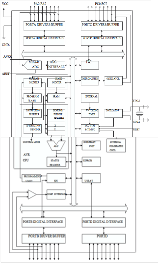
IJSER © 2014 http://www.ijser.org