pain conditions the subjective approach fails. To overcome this failure we used the objective EEG approach to detect pain in human body.
International Journal of Scientific & Engineering Research, Volume 3, Issue 11, November-2012
ISSN 2229-5518
Dr. A.Q Khan Institute of Computer Sciences & Information Technology(KICSIT) Kahuta, Pakistan affiliated with University of
Engineering & Technology(UET) Taxila, Pakistan.
nasir.malik44@gmail.com[1], asim_engineerinside@yahoo.com[2], iqbal.nazish26@gmail.com [3], xainab_hafeez@yahoo.com[4]
Abstract -- Objective was to develop a system that makes difference between EEG patterns, to detect pain. Keeping in mind this phenomena the techniques were explored to develop such a system. Literature studies further cleared that acute pain signals moving from all part of human body to brain consists of certain frequencies bands between 0-98.4Hz. Further banding includes eight different bands in which different pains show their responses.
Skin on the human skull is rough and it’s bad conductor for getting signal out of it, thus skin is prepared by rubbing to remove dead cells, using a simple glass rod. After that EEG conductive paste is applied and skin is again rubbed to fill the porous surface of skull.
Ag/AgCl electrodes with gold contacts are used for getting the signals. These are special purpose electrodes made for picking signals of very low voltage (µV) range. EEG gel is applied on the electrodes to make a better conductive contact between skin and electrode. The locations of the skull are decided by ‘International 10-20 System for Electrode Placement’.
Two channel electrodes with Uni-polar referencing system are used to get the signals. Signals captured are passed through sophisticated electrode wire with very low impedance and moved to the special purpose bio-medical instrumentation amplifiers. These amplifiers have very high gain of
10,000 and have CMRR as low as 100dB. These amplifiers amplify the signals and reject the common noise at the same time. Amplified signals are moved to 5th order Bessel filter with cutoff frequency of 98.4Hz. The filter rejects the frequencies after 110Hz and keeps all others. Impedance matching further makes few revisions in the design.
The signals are thus digitized and sent to PC by using microcontroller. In MATLAB software further banding in performed using 16th order FIR
digital filters. There plots are made and now the system is ready. Physician can check the band response of any subject.
Data is recorded to make a healthy benchmark and the Co-relation and Euclidian techniques are applied to calculate the difference of subject having pain and healthy benchmark.
—————————— ——————————
In the daily life we observe that there is no perfect method to detect pain in human body. There are certain methodologies used to have a vague idea about the pain i-e EMG. The objective of the research was to develop a system that differentiates between pain and other signals activity at human skull. For this purpose we took the EEG technology to develop our system for pain monitoring. There are two approaches for the measurement of pain (subjective and objective). The subjective approach is most widely used technique for pain measurement due to unreliable and uncommon objective approach (1). But when we come to infant children and the patients with inability to describe their![]()
pain conditions the subjective approach fails. To overcome this failure we used the objective EEG approach to detect pain in human body.
Pain killer is a cure for pain, but when it comes to the intensity of pain the physician have to rely only on the condition told by the patient. The patient’s inability to describe exact condition or the exaggerations about the condition leads to over doze of medicine that has harm effects in human body.
International Journal of Scientific & Engineering Research, Volume 3, Issue 11, November-2012
ISSN 2229-5518
If the physicians have a quantitative method to measure the exact pain he/she will be in better position to prescribe a cure.
If the patient’s immunity level is very down the pain killer’s extra doze may be the poisonous.
To overcome all the above situations and keeping in
mind budgetary conditions a research was conducted to develop an EEG based system to detect pain in human body.
The system consists of efficient and cheap hardware acquisition system that takes data in the form of electrical pulses from human skull with respect to human earlobe reference. The data taken is in amplitude range of 10-100µV and consists of all the frequencies that EEG includes. Bi-channel system is designed to take data from two locations at a time. The signal then travels to amplification unit. For white noise removal, amplification unit consists of BIO-medical instrumentation amplifiers that reject noise (CMRR) up to 100dB (2). After the noise removal and amplification up to 100,000 the signal got strengthened to be accepted as input by a low pass fifth order Bessel filter. The filter has cut off frequency of 98Hz, as all the frequencies of pain understudy lies between ranges of 0- 98.4 Hz (3). After getting the signal from the filter the signal was digitized with sampling frequency of 220Hz, lightly greater than twice the frequency of highest frequency component, using 10 bit ADC of PIC microcontroller. Then the signal was sent to a personal computer for further signal processing and plotting. Signal processing involves the conversion of sampled date to waves by taking their discreet cosine transform. Then the signal is applied under following filters to get their responses. All the filters were designed for 16th order FIR using hamming window. Bands reflects different pain conditions (3)
Delta (1.600-3.100Hz), Theta (4.700-6.300Hz), Alpha1 (7.800-9.400Hz) Alpha2 (10.900-1200.5Hz), Beta1 (14.100-17.200Hz), Beta2 (18.500-25.00Hz), Gamma1 (26.600-56.300Hz) Gamma2 (62.500-98.400Hz).
![]()
After that the captures signal data is compared with a bench mark saved reference healthy subject data to get the final pain figure.

Goal of the project is to develop a system to detect the pain signals, a non-invasive objective approach towards pain detection. Specific objective is to develop a system that differentiates between pain and other signals received from the brain. Methodology of the project is shown in the Fig. 1.1
Signal from Brain to EEG Electrode
Amplification
Filtration
Digitization and Interfacing to
PC
Software Signal Processing
Comparison & Final Plots
Figure 1.1: Methodology
Recording of EEG is significantly reliant on the selection of gel and electrode. We used reusable silver- silver chloride disc electrodes. The finest outcomes were obtained with the reusable sintered Ag|AgCl electrodes. Additional types of reusable electrodes suffers from changes in properties because of wear and tear [4], low- frequency noise, and high resistance.
Low impedance highly conductive EEG gel, is used between the electrodes that forms contact between the skin and the electrodes. This is washable, non-drying conductive paste.
International Journal of Scientific & Engineering Research, Volume 3, Issue 11, November-2012
ISSN 2229-5518
![]()
EEG signals are recorded non-invasively by placing an electrode cap on the scalp of the user in such a way that the location of the electrode corresponds to some particular underlying brain area. We have used a pair of electrodes over the skull for getting the signals of interest i.e. Pain Signal, placed at two sites that refer to the location of generation of Pain Signals. To measure these voltages, a common reference has to be set. This may be any location on the scalp, which does not contain important information about the tasks to be classified. The EEG signal is generally sampled at a frequency of 1-
2 Kilo samples/s. Once sampled, it must be pre- processed. To remove the effect of instrumentation and environmental noise, the acquired EEG signal is passed through a low pass filter before digitization and further filtration is done after digitization. We will be getting the frequency domain for Pain Signal on experimentation Basis, as it is not defined exactly.
The different ways of combining electrode pairs to measure potential differences on the head and electrode placements represent the electrode montage. In EEG montage there are many recording ways [5], we used bipolar recordings, in which possible differences among contiguous scalp electrodes are measured.
Anterior Parietal Lobe: It processes localize touch and sensory information, pressure, temperature on the opposite side of the body side, and pain
Superior Parietal Lobe: Accountable for spatial processing, nisual guidance of hands, fingers, eyes, and limbs, head and responsive to eye movements etc.
Inferior Parietal Lobe: Spatial cognition, such as arithmetic and reading [7]. Parietal lobe is accountable for the processing of nerve impulses associated to the senses, such as temperature, pain, touch, pressure, and taste. [8], [9]
The parietal lobes are superior to the occipital
lobes and posterior to the central and frontal lobes. In our project part of interest, for getting the pain signals is Parietal Lobe. [10].
The 10-20 system is based on relationship between the underlying area of cerebral cortex and the location of an electrode. The most extensively used system to describe the location of scalp electrodes is the International 10–20
System of Electrode Placement.
Each site has a letter (to identify the lobe) and a number or another letter to identify the hemisphere location. The letters used are: "T"-Temporal lobe, "F"-Frontal lobe "C"- Central lobe, "O"-Occipital lobe, "P"-Parietal lobe. Even numbers (2,4,6,8,10) refer to the right hemisphere and odd numbers (1,3,5,7,9) refer to the left hemisphere. "Z" refers to an electrode positioned on the midline.
The smaller the number is the closer the position to the midline will be. "Fp" stands for Front Polar. The point between the nose and forehead is ―Naison‖. And the bump at the back of the skull is ―Inion‖. Centimeters (cm) are the unit of measure in the 10-20 system. 10% and 20% refer to interelectrode distance derived from three main measurements: preauricular points, circumference of the head, and nasion–inion.
For this project Active Electrodes should be placed at P3, P4 for Pain Signals. These point locations are in the Parietal Lobe [11], [12].
3.8 Amplification
In general, any device that changes, generally increases, the amplitude of a signal is called amplifier. And the process of amplifying the signal amplitude is called amplification.
A number of specifications characterize the quality of an amplifier e.g Bandwidth, Efficiency, Gain, Linearity, Output dynamic range, Noise, Slew rate, overshoot, Settling time and ringing, Rise time and stability.
The signal we are getting from the EEG electrodes is of
very low power i.e. of micro volts but the input that is required by the filter is of volts so we have amplified our signal to that level. This is done by using amplifier IC circuits. AD620(low power, low cost instrumentation amplifier) and LM741(general purpose operational amplifier, for summer only)
AD620: AD620 is an operational amplifier, mostly used in medical applications; it works well as a preamplifier due to its low input voltage. It is a low cost, high accuracy instrumentation amplifier with only one
International Journal of Scientific & Engineering Research, Volume 3, Issue 11, November-2012
ISSN 2229-5518
![]()
external resistor to set its gain of RG between pin 1 and 8. Gain range is 1 to 10,000.
LM741: Enhanced performance over industry standards like the LM709. LM741 are direct, plug-in replacements for the MC1439, 709C, 748, and LM201 in most applications. It provides overload protection on the output and input. No latch-up when the common mode range exceeds, also as freedom from oscillations.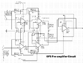
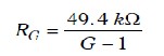
Figure 4.4: Amplifier Circuitry
3.9 Filtration
Bessel Filter: Bessel filter is a type of filter with a maximally flat group delay (maximally linear phase response).
Bessel Filter Characteristics: Bessel filters are frequently used in audio crossover systems.
Analog Bessel filters have property of nearly
constant group-delay throughout the entire pass- band, thus preserving the wave shape of filtered signals in the pass-band.
We use Bessel Low Pass Filter in our project because
it has good phase response, exhibits a nearly constant time delay to frequencies within the pass- band and flat magnitude response in pass-band.
Filter Order: The order of a filter can be defined as the number of previous inputs used to calculate the current output. In our project Fifth Order Active Low Pass Filters are used, order of filters is shown in Fig. 5.2.
Higher-Order Low-Pass Filters: To sharpen a desired filter characteristic the Higher-order low- pass filters are required. For this purpose, first-order and second-order filter stages are joined in series, as in Fig. 5.2 so that the product of the individual frequency responses results in the optimized frequency response of the overall filter.
A filter with an even order number include
second-order stages only, while filters with an odd order number consists of an additional first-order stage at the beginning.

Figure 5.2: Orders of Filters
Filter Calculations and Design: Calculations for filters are done by the use of following formula,
First Order
R1=a1/ (2πfcC1) Second Order
R1, 2= (a2 C1,2±√( (a2 C1,2)2-4b2C1C2))/ (4πfcC1C2)
Bessel Filter Coefficients (a, b) for Fifth Order are mentioned in the table 5.1 below
Table 5.1: Bessel Filter Coefficients
Stage | A | B |
1 | 0.6656 | 0 |
2 | 1.1402 | 0.4128 |
3 | 0.6216 | 0.3245 |
Signal was filtered by using a low pass filter as in Fig.
5.3, because signals generated by brain are of frequency from 0-98 Hz. Choosing the right filter is one of the most
International Journal of Scientific & Engineering Research, Volume 3, Issue 11, November-2012
ISSN 2229-5518
![]()
important tasks in any system involving signals. To remove unnecessary frequency components from the signal called noise filtering process is done.
To increase accuracy, a higher order for the filter was chosen. A higher order filter improves the cut-off slope, reducing the unwanted frequencies appearing in the pass band as in Fig. 5.1.
However, the order cannot be increased beyond bounds as it increases the complexity of the system, which in turn not only becomes computationally expensive but also starts affecting the pass-band frequencies.
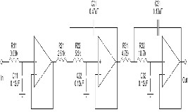
Figure 5.3: Filter Circuit
Analog to Digital Convertor (ADC): PIC18F452 has built in 10 bit ADC. Conversion Time: 192usec ADC
Conversion time=conversion clock source * 12
Using Vref+= 2.5V &Vref- = -2.5V
Conversion Clock Source Fosc/64
Channel Selection, Channel 0(AN0)
Data right justified: 6MSbs of ADRESH are 0s. Data Acquisition delay is 7.5usec.
Then the data gets sampled and we got integer values from 0-1024. The values from 0-511 are actually negative peaks of the wave, and the values 512-1023 are positive peaks of the input wave. We send this data serially using serial port module.
Serial Data Transmission:
Baud Rate: 4800s/sec: used for maximum data accuracy with error of 0.15%
SPBRG Value:12
Using Simplex one way communication
For conversion from TTL logic to PC logic we used standard MAX232.
The data from the serial is received in MATLAB and thus formatted in its original format with positive and negative peaks of samples. Following is the process flow chart of the objective pain measurement program
Fig. 7.1.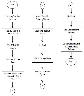
Figure 7.1: Block Diagram
Receiving Data from Serial: Data from the serial port is received in the form of bytes. The data is then formatted in the form of int16 and saved on file.
Take DCT: A discrete cosine transform (DCT) expresses a sequence of finitely many data points in terms of a sum of cosine functions oscillating at different frequencies. We need samples in the form of sin (cosine) waves, so we take the discreet cosine transform of the input samples. Then as a resultant we will get cosine waves of each sample.
Creating Hamming Windows: Richard W.
Hamming proposed the "raised cosine" with
these particular coefficients. To minimize the
International Journal of Scientific & Engineering Research, Volume 3, Issue 11, November-2012
ISSN 2229-5518
![]()
maximum (nearest) side lobe the window is optimized, it is given a height of about one-fifth that of the Hann window, a raised cosine with simpler coefficients [19].![]()
Note that
Now for FIR digital filters, windows are created for the Pain bands mentioned in IEEE Paper: Identifying frequency domain features for objective pain measurement system (Rissacher, Dowman, & Schuckers, 2008)[20].
Applying FIR filters on input signal:
Finite impulse response or FIR is a type of a
digital signal processing filter, its impulse
response is of finite duration, because it settles to zero in finite time. Impulse response of an Nth-order discrete-time Finite impulse response or FIR filter (i.e. with Kronecker delta impulse input) lasts for N+ 1 sample, and then it goes to zero.
Discrete-time FIR filters are shown by the
following equation, which shows the output y in terms of its input x:![]()
Where:
x[n] is the input signal,
y[n] is the output signal,
bi is filter coefficients, also recognized as tap
weights, and
N is filter order – an Nth-order filter has N+1
entities on the right-hand side. These are usually referred to as taps (the no. of inputs), and one may talk of a "5th order/6-tap filter".
The equation can also be shown as a convolution of the coefficient sequence bi with the input signal,
That is, the output of filter is a weighted sum of the recent and a limited number of previous values of the input.
Fast Fourier Transform OR (FFT): Fast Fourier transform is a efficient algorithm for computing the discrete Fourier transform or DFT. An FFT calculates DFT and gives precisely the similar result as evaluating the DFT definition directly; only dissimilarity is that an FFT is greatly faster. (Many FFT algorithms are also much more precise in the round-off error’s presence than evaluating the DFT definition directly, as discussed below.)
Let x0, ...., xN-1 be complex numbers. The DFT
is defined by the formula:
To analyze the number of harmonics of a particular frequency band we took the FFT of each band.
Algorithms: An algorithm is an efficient way to solve a problem expressed as a limited sequence of steps. Algorithms are used for data processing calculation, and a lot of other fields. To compare our runtime results/data with reference data we need an algorithm that can provide more accurate results of the comparison. Correlation is used for this purpose.
Correlation: Correlation is statistical measurement of the relationship among two
variables. A correlation is a single number that describes the degree of relationship between two variables. Probable correlation range is +1 to –1. There will be no relationship between the variables if correlation measurement gives a zero. If it’s a correlation of -1 it indicates that there is a perfect negative correlation, denoting that as one variable goes up, the other goes down. If it’s a correlation of +1 it indicates that there is a perfect positive correlation, denoting that both of the variables are moving in the similar direction simultaneously. For comparing
International Journal of Scientific & Engineering Research, Volume 3, Issue 11, November-2012
ISSN 2229-5518
![]()
two variables of reference data and the runtime data we take correlation between the two values. Take 2 healthy subjects, 1 male and 1 female and took EEG recordings for 1 minute. There data has been averaged and saved for reference. Now an injured patient data is collected and correlation is taken between two data. If result is more positive it means that the patient is healthy, otherwise their band data is plotted and analyzed for getting assured that he/she is suffering from pain.
The final plots show the number of harmonics of the band frequencies. From which the physician can get the clear picture of the pain bands for a particular subject and from the correlation and Euclidian results, he/she will be clearer about the pain signal.
The final plots are actually pain-graphs as cardiograph.
Enhancements Technique: The methodology that is required to detect the pain is developed and tested. Now healthy & improved reference is required to benchmark the difference between the ordinary brain signals and pain signals. For this purpose the system is used to create the bench mark.
Following are recommendations for benchmarking.
Take 20 subjects of different age group and gender; prepare effective questionnaires to know that there is no pain or anxiety in the subjects. Take readings at different times and then create a weighted average.
Reduce the noise level of amplifiers, to make
signals more accurate.
Shift the interfacing with PC from PIC microcontroller to sound card. Modulate the signal and give that directly to the PC sound card. This will be more effective and fast way to get signals to PC.
Effectively test the system to increase accuracy
of the system.
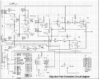
Here is the complete system schematic for objective pain measurement system.
Figure 8.3: Circuit Diagram
I would like to acknowledge and extend my heartfelt gratitude to the following persons who have made the completion of this paper possible:
ALLAH Almighty,
Our Dean, Dr. Muhammad Afzal ,for his vital encouragement and support.
Mr. Engineer Usama Sardar, our supervisor for the continuous reminders and much required enthusiasm and motivation.
All KICSIT’s faculty members and Staff.
Most especially to our family and friends.
7. REFERENCES
[1]Identifying frequency-domain features for an EEG- based pain measurement system [Conference] / auth. S.A.C Rissacher D. Dowman R Schuckers. - Long Island, NY : IEEE Xplore, 2008.
[2]Measurement of pain [Journal] / auth. Katz J Melzack
R // PubMD. - 1999.
[3]datasheet AD620 [Journal] / auth. Semiconductors
National.
[4]P. Tallgrena, S. Vanhataloab,K. Kaila, J. Voipioa
―Evaluation of commercially available gels and
International Journal of Scientific & Engineering Research, Volume 3, Issue 11, November-2012
ISSN 2229-5518
electrodes for recording of slow EEG potentials
―Accepted 8 October 2004.
http://www.clinph-journal.com/article/S1388-
2457(04)00390-6/abstract last visited 29th April 2010
[5] weblink:http://www.scholarpedia.org/article/Electroe ncephalogram
[6] weblink:http://library.thinkquest.org/J002391/function s.html
[7] Human Brain (Anatomy) [Online]
http://brainanatomy.net/str6.html
![]()
[8]http://www.brainhealthandpuzzles.com/brain_parts
_function.html
[9] http://www.ehow.com/facts_5626974_part-brain- registers-pain_.html
[10]http://biology.about.com/library/organs/brain/bl parietallobe.html
[11] http://www.measurement.sk/2002/S2/Teplan.pdf
[12] Brain Master Technologies, Inc. home page. http://www.brainmaster.com/generalinfo/electrodeus e/eegbands/1020/1020.html.
[13]http://alteredstate.com/index2.htm?/brainmaster/t rodinst.htm