International Journal of Scientific & Engineering Research, Volume 4, Issue 12, December-2013 239
ISSN 2229-5518
Mathematical Modeling and Control System
Design of Tiltrotor UAV
Shlok Agarwal, Apoorva Mohan, Kamlesh Kumar
Abstract— Rotorcraft is always a challenging field among the researchers due to critical application in aerospace. There has been much advancement in the field of UAVs and UAV telemetry. Scientists have increasingly started to focus on VTOL (vertical take - off and landing) aircrafts and are exploring different types of control systems to increase the stability of the UAV and make it autonomous. The tiltrotor UAV discussed in this paper is a kind of a helicopter having two main propellers instead of one and no tail fin. All three important motion of the aircraft i.e. roll, pitch, yaw are controlled by thrust vectoring by tilting the rotors using servo motors and changing the magnitude of thrust using electronics speed controllers. There is a camera fixed on the model and the VTOL makes it fit for effective video surveillance. The paper discusses the mathematical model and control system of a Tiltrotor UAV.
Index Terms—Twinrotor, UAV, Thrust, Moment, Force, Propeller, BLDC
—————————— ——————————
Nomenclature:
T Thrust
Vs Downwash Velocity
w Angular velocity
I. INTRODUCTION
Unmanned Aerial Vehicles (UAV) is unmanned flying aircrafts. They are different from the commercial aircrafts and jets in a way that it does not have an on board pilot.
IJSER
ρ Density of Air
d Diameter of propeller
F Force
M Moment
m Mass, Kg
I Moment of Inertia
Generally the pilot in a UAV controls the motion from the
ground through a remote. Advanced development [2 3] in the field has resulted in autonomous UAVs and the need of a pilot is eliminated. [7 9] explain the concept of UAVs very well. Such UAVs have an on-board controller that takes care of the stability and the trajectory motion of the UAV. Applications are often focused on the military areas,
CT
Cl , p
Thrust coefficient
Propeller Moment Coefficient
surveillance, inspection of transmission lines and power distribution; low cost filming and panoramic picturing for
the movie industry, sport events, crop and herd
l, m, n Moment in x, y, z axis
p, q, r Body frame angular velocities
u, v, w Body frame velocities
x, y, z Inertial Positions
() p Propeller
()T Total
()x Body x-direction () y Body y-direction ()z Body z-direction
————————————————
• Shlok Agarwal is currently pursuing bachelors degree program in Mechatronics engineering in Manipal University, India, E-mail: shlok@hotmail.co.in
• Apoorva Mohan is currently pursuing bachelors degree program in Mechatronics engineering in Manipal University, India, E-mail: priyam.apoorva@gmail.com
• Kamlesh Kumar is currently an Assistant professor aeronautical and automobile engineering in Manipal University, India, E-mail: kamlesh208755@aero.iisc.ernet.in
monitoring, among others.
A twin rotor-type UAV is a type of helicopter which is propelled by two rotors. The blades rotate in opposite directions to counter act the torque produced by each motor. The tail rotor is not required in order to counter act the angular momentum of the propellers. As a coupled dynamical system, by altering the motor speed, the position is also changed. The system is under actuated and very dynamically unstable. In many situations it is desirable that the system is to be as small as possible to achieve large movements, being able to move both vertically and horizontally. Specific characteristics, such as vertical flight ability and flying at low speeds, allow the model to perform tasks which are difficult to implement through other mechanisms and structures. With demand of applications for this kind of aerial vehicle rapidly increasing also increases the interest in research, both in industry and academics. Several studies
IJSER © 2013 http://www.ijser.org
International Journal of Scientific & Engineering Research, Volume 4, Issue 12, December-2013 240
ISSN 2229-5518
based [4 6 8] are being conducted on the dynamics and
describing methods to regulate their flight by adding automatic stability control through a diversity of hardware and software control schemes.
Mathematical models vary from model to model. There are numerous ways to design a model. It is one of the most important parts of a UAV and is designed before fabrication process of the UAV. Similarly the control system is unique and essential. Advanced research on linear and non linear control systems for UAVs is carried on. The objective of this work is to describe a mathematical model and a control system designed for a tiltrotor UAV described in [5].
II. MATHEMATICAL MODEL
A. Motor Characteristics
There are two types of motors used in the model.
produces a torque around the axis generating an angular
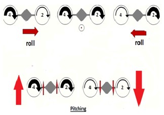
acceleration. Servo motors are used to tilt the motors to provide thrust vectoring, through which the forward and backward motion of the copter can be controlled. The three fundamental motions roll pitch and yaw movements are obtained as follows:
Pitching is done by increasing the speed of rotation of the motors and inclining their axis of rotations in the same direction. This change in direction is brought by using servos. Rolling is achieved by varying the speed of rotation in of either motor. In figure 1, the motor which has greater speed produces a higher thrust thus creating a rolling effect in opposite direction. Yawing is achieved by inclining the axis of rotation of BLDC opposite to each other. This is also done by using servo motor.
A.1. Brushless DC Motor
The following relations for the variation of torque, downwash velocity and moment are well illustrated in [1]. There is a huge amount of difference in the theoretical and practical values obtained while flight testing. The result analysis section at the end shows the linearized graph considering certain experimental values.

Tp = CT
wp 4
d p
2Tp
Figure 1. Rolling and pitching
B.1. Newton Euler Modeling
Newton Euler equation describes the combined translational and rotational dynamics of a rigid body.

. Vs =
ρ Ap
2
The resultant force and torque about the center of
gravity is illustrated in the equation below:
M = C
ρ wp d 5

p l , p p
A.2. Servo Motor
Servo motors are chosen based on their angle of rotation, stall torque and their response time. Servo motor characteristics are different for different servo motors.
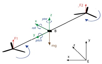
B. Rigid Body Dynamics
The tiltrotor type UAV is driven by two brushless DC motors to produce thrust and two servo motors to give direction to the thrust. Figure 1 illustrates the direction of movement of the propellers with black arrows (the width is proportional to the speed of the rotors). Red arrows
Figure 2. Coordinate Axis of the Model
indicate the direction of the movement of the structure as
F m
0 a 0
whole. An increase (decrease) in the speed of the rotor
T =
cm
causes the copter to move up (down) vertically. The variation of the two rotors placed on the same axis
M T 0
Icm α
ω × Icmω
IJSER © 2013 http://www.ijser.org
International Journal of Scientific & Engineering Research, Volume 4, Issue 12, December-2013 241
ISSN 2229-5518
B.1.1 Propulsive Forces and Moments
The force applied by the propeller is due to the thrust produced by the propeller. The direction of force at different intervals depends on the angle between the motor axis and the axis passing through the nose of the
aircraft ( ς ). The force produced by the propeller is given
by:-
Tp cos ς
B.2 Translational and Rotational Motion Dynamics The translational motion dynamics equation and rotational motion dynamics equation can be simplified from the 6 degree of freedom equations. Translational Motion Dynamics give a relation for the translational velocity and translational velocity rate. Rotational Motion Dynamics give a relation for the rotational angle and rotational velocity rate. These equations are standard
equations used in modeling a UAV.
FP = 0
Tp sin ζ
u
rv − qw
f
x
1
v

= pw − ru + m f y
The moments produced by the propeller depends on
the thrust produced and the angle ς . It is a common
finding that the center of mass of the aircraft does not
qu − pv
z
coincide with the center of gravity. Assume that it is at a
p
Γ l +Γ n
Γ pq −Γ qr
distance ( x p ) from the center of gravity in the x axis and
=1
1 2
2 2
= + Γ −Γ −
at distance ( z p ) from the center of gravity in the z axis.
q J m
5 pr
6 ( p r )
r y
Γ
pq −Γ qr
l
lm / 2* (Tp1 − Tp 2 ) sin ζ
Γ4l + Γ8 n
7 1
m = xp (Tp1 + Tp 2 ) sin ζ − z p (Tp1 + Tp 2 ) cos ζ
n
lm / 2* (Tp1 − Tp 2 ) cos ζ
IJSER
B.1.2 Forces and Moments due to gravity
The force applied by the gravity is in the downwards direction of the vehicle frame. All calculations are being made in the body frame. The rotation matrix from vehicle frame to body frame is applied to get the force due to gravity in the body frame.
−mg sin θ
F = mg cosθ sin φ
mg cosθ cos φ
M g = 0
B.1.3 Total Forces and Moments
The forces and moments due to the propeller, gravity and aerodynamics are added together to get the resultant forces and moments. The UAV designed does not have a wing or any control surface. Thus we can assume that the force and moment due to aerodynamics is zero. The forces and moments can be broken down in their respective three components.
FT = Fp + Fg
M T = M p + M g
^ ^ ^
III. CONTROL SYSTEM DESIGN
The modeling of a UAV is the first step in the process of building one. Once the UAV is fabricated, there comes a need of a control system to control the control surfaces, stabilize the flight and maneuver the aircraft .There is a lot of research going on linear and non-linear control systems [10]. The need to design non-linear control systems is that majority of the parameters obtained during flight are non-linear. This is confirmed by the data obtained by a Flight Data Recorder (FDR). If the parameters are linearised there is a significant amount of change in the output. But designing a non linear control system is both challenging and complex. The control system designed in this paper is a preliminary linear PID control which switches between two different modes.
1. Climb Velocity Control
2. Altitude Hold Control
FT = Fx i + Fy
j + Fz k
Figure 3.
IJSER © 2013 http://www.ijser.org
International Journal of Scientific & Engineering Research, Volume 4, Issue 12, December-2013 242
ISSN 2229-5518
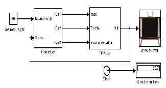
The controller is designed in a way to climb at a velocity of 1 m/s and hold altitude once it reaches 80m. The values in the Simulink Simulation can be changed according to the need.
The block set shown in figure 3 are the complete layout of the Simulink Model. It shows the tiltrotor controller and dynamics block. The draw aircraft block plots the final output of the simulation in the form of 2D and 3D graphs. The desired height is set at 80 meters. The climb velocity by default is set at 1 m/s inside the block.
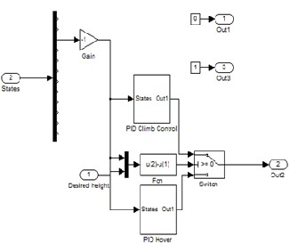
The block set shown in figure 4 are the internal structure of the controller block. The twelve states of motion are sent as feedback to the controller block. The controller block takes desired height as a reference input. The controller block shows a switch between the two controls- climb control and hover.
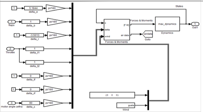
The block set shown in figure 5 is the internal structure
of the tiltrotor block shown in figure 2. The layout consists of delta inputs and wind inputs. The delta inputs are the inputs taken from any control surfaces if present of the model. The wind can be assumed to be zero. The states act as feedback for calculating forces and moments. The forces and moments block at a particular instant calculate the force and moment along different axis. The dynamics block shown is an s-function and it calculates the states at a particular instant. This output is displayed in the form of graphs and also is used as feedback in the forces and moments block.
IV. RESULT ANALYSIS
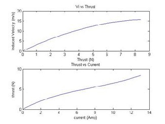
A. Motor Thrust
The thrust varies with input current to the BLDC. Induced velocity increases with the increase in thrust. Data is linearized considering some experimental data.
IJSER
Figure 4.
IJSER © 2013 http://www.ijser.org
International Journal of Scientific & Engineering Research, Volume 4, Issue 12, December-2013 243
ISSN 2229-5518
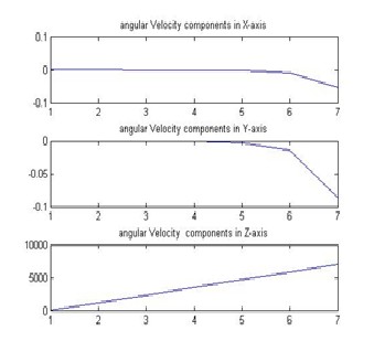
Figure 5
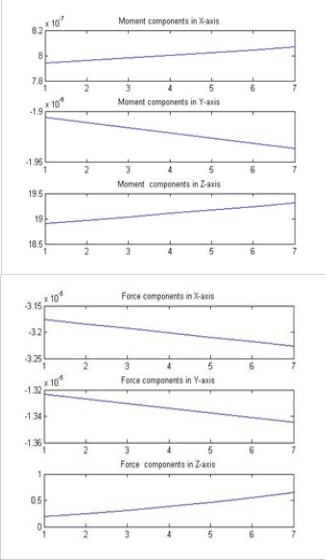
B. Forces and Moments
The forces and moments in the three axis are plotted with respect to time. The graphs are plotted for the first seven seconds during take-off. It can be observed that the forces and moments experience a change in the z axis. The values in the x and y axis are in the order of zero

IJSER
C. Velocity
It can be observed from the graph that the values till the first 6 seconds are constant in the x and y axis. After the
6th second there is some disturbance due to release from the ground. The velocity in the z axis increases almost constantly.
D. Final Result
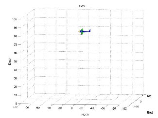
The above three dimensional plot shows how the model hovers at the set desired height.
IJSER © 2013 http://www.ijser.org
International Journal of Scientific & Engineering Research, Volume 4, Issue 12, December-2013 244
ISSN 2229-5518
V. CONCLUSION
In this paper we have proposed a mathematical model of a twinrotor UAV. A linear PID controller is designed which switches between two model. Such a design will be a good solution for a tiltrotor UAV. A Simulink simulation along with results is clearly explained. The motor thrust characteristics and dynamic states are plotted in a graph and results are analyzed.
REFERENCES
[1] Nathan Knoebel, Stephen Osborne, Deryl Snyder, T timothy, Mclain, Randal Beard, Andrew Eldredge- Preliminary Modeling, Control, and Trajectory Design for Miniature Autonomous Tailsitters, AIAA Guidance , Navigation and Control Conference and Exhibit 21-24 August 2006, Keystone, Colorado.
[2] S.K Kim, D.M Tilbury- Mathematical Modeling and Experimental Identification of a Model Helicopter- AIAA Journal of Guidance, Control and Dynamics August 31, 2000
[3] Rahul Goel, Sapan M Shah, Nitin K Gupta, N Ananthkrishnan-Modeling, Simulation and Flight Testing of an Autonomous Quadrotor, ICEAE 2009
[4] Li Haixu, Qu Xiangju, Wang Weijun- Multi-body Motion Modeling and Simulation for Tilt Rotor Aircraft- Chinese Journal of Aeronautics 23(2010) 415-422
[5] Shlok Agarwal, Apoorva Mohan, Kamlesh Kumar- Design and
Fabrication of Twinrotor UAV, CMCA-2013
[6] Sergey Shkarayev, Jean-Marc Moschetta, Boris Bataille- Aerodynamic Design of VTOL Micro Air Vehicles- 3rd US-European Competition and Workshop on Micro Air Vehicle Systems( MAV07).
[7] Unmanned Aerial Vehicles- Beard and McLain
[8] Rejane Cavalcnte, André Luiz C. de Araújo-] Design and Construction of a Quadrotor-type. Unmanned Aerial Vehicle: Preliminary Results.
[9] Unmanned Aerial Vehicles- Rogelio Lozana
[10] Voos, H. - Nonlinear control of a quadrotor micro-UAV using feedback-linearization, Mechatronics, 2009. ICM 2009. IEEE International Conference on Date 14-17 April 2009
IJSER © 2013 http://www.ijser.org