International Journal of Scientific & Engineering Research, Volume 5, Issue 7, July-2014 615
ISSN 2229-5518
1Atanda, P. O., 1Abioye, A. A., 1Olorunniwo, O. E. and 2Oluwole, O. O.
1Department of Materials Science and Engineering, Obafemi Awolowo University, Nigeria.
2Department of Mechanical Engineering, University of Ibadan, Nigeria.
Corresponding author: Oluwole.O.O; email:oluwoleo2@asme.org
Abstract -The study investigated the material selection for the fuel fired crucible furnace using bubble charts . The results were generated using GRANTA software. Different properties were considered during the selection of the materials for the furnace. The appropriate engineering materials were sought locally for the design and construction of the fuel fired cruc ible furnace. Among several parameters taken into consideration are strength/weight ratio, formability, cost and ability to fulfill specific serv ice functions. All these were taken into consideration during the material selection process for the fuel -fired crucible furnace. These properties were plotted against each other in bubble chart and the selection of the appropriate candidate material was done on the bubbl e chart. The software plotted the properties of each unit of the furnace in form of bubbles and the candidate material where selected from the bulk of materials suggested by the software. The functions, objectives and constraints of the parts or the units to be designed were adequately specified and the material properties to be selected were determined based on these fundamental parameters.
Index terms: material selection, material properties, bubble chart software, crucible furnace,
—————————— ——————————
1. INTRODUCTION
Although melting is carried out with a high degree of success in industry and research institutes in developed countries, where sophisticated but often proprietary and /or patented processes and operations are in use, there have been reported cases of poor performance of locally made crucible melting furnaces probably due to inability to retain heat as a result of poor design and material selection [1] . Nigerian local foundries and research laboratories are yet to come to terms with this unique procedure. The local foundry and machine tool industries currently use very poorly designed and constructed batch-type muffle-air-circulation furnace equipment. These equipment are beset with a number of problems. One, they are generally grossly inefficient energy-wise and are operated at widely varying sub-optimal conditions leading to products with a wide variation of properties. Secondly, the processes are arduous because practically all operations are done manually. Thirdly being a batch-type operation in most cases, the throughput is low [1]. Also most of the furnaces used in the local industries are heavy and bulky due to poor material selection.
Furnaces are normally heated with some source of heat which should be such that the supply of heat to the furnace chamber can be controlled easily. Heat is generated in furnaces to raise their temperature to a level somewhat above the temperature required for the process, either by combustion of fuel or by conversion of electric energy to heat [2],[3],[4],[5]. Fuel-fired furnaces can be classified depending on the type of fuel; solid, liquid, and gaseous fuel. Commonly used solid fuel is coal or coke while that of liquid fuel is fuel oil. Gasoline and kerosene are liquid fuels that can be used successfully as they are easy to store and controlled, however, cost is the major limitation. Fuel-fired furnace can attain temperatures as high as 1200 0C or more. Such furnaces are economical at high temperatures [2],[3],[4],[5].
Materials of construction of fuel-fired crucible furnaces are engineering materials of outstanding electrical, thermal and mechanical properties. These materials may be monolithic or composite based. Composites are materials in which the desirable properties of separate monolithic materials are combined mechanically or metallurgically [6],[7]. Each of the components
IJSER © 2014 http://www.ijser.org
International Journal of Scientific & Engineering Research, Volume 5, Issue 7, July-2014 616
ISSN 2229-5518
retains its structure and characteristic, but the composite generally possesses better properties.
Composite materials offer superior properties to conventional alloys for various applications as they have high stiffness, strength and wear resistance. Mechanical performance is fundamental to the selection of a structural material. Desirable properties are high strength, high modulus (stiffness), high ductility, high toughness (energy absorbed in fracture), and high capacity of vibration damping [8]. Strength, modulus and ductility can be measured under tension, compression or flexure at various loading rate, as dictated by the type of loading on the structure. A high compressive strength does not imply a high tensile strength. Brittle materials tend to be stronger in compression than tension due to the micro-cracks in them. High modulus does not imply high strength, as the modulus describes the elastic deformation behavior whereas strength describes the fracture behavior. Low toughness does not imply low capacity for damping (energy dissipation) may be due to slipping at the interfaces in the material, rather than being due to the shear of a visco-elastic phase in the material. Other desirable mechanical properties are fatigue resistance, creep resistance, wear resistance and scratch resistance. Among the metal based structural materials, steel and aluminum alloys are dominant. Steel is advantageous due to its high strength, whereas aluminum is advantageous due to its low density. For high temperature applications, intermetallic compounds (such as NiAl) have emerged though they suffer from brittleness. Metal-matrix composites are superior to the corresponding metal matrix due to their high moduli, high creep resistance and low thermal expansion coefficients, but they are expensive due to their processing [8].
Generally, the fuel fired crucible furnace is made up of four units; the furnace shell, the refractory lining of the crucible furnace, the flame gap and the crucible pot. For each of these units, structural applications are of paramount importance. These are applications that require mechanical performance (e.g., strength, stiffness and vibration damping ability) in the material, which may or may not bear the load in the structure [8]. In addition to mechanical properties a structural
material may be required to have other properties, such as low density (i.e., be lightweight) for to save
fuel in the case of aircraft and automobiles, to facilitate high speed in case of race bicycles, and for easier handling in the case of wheelchairs and armor. Another property that is often required is corrosion resistance, which is desirable for the durability of all structures, particularly automobiles and bridges. Yet another property that may be required is the ability to withstand high temperatures and/or thermal cycling, as heat may be encountered by the structure during operation, maintenance or repair. The basic mechanical properties have an important influence on the loading-bearing ability and structural performance of the material. Load- bearing ability means that the material has adequately high values of strength, modulus and ductility under loading condition that is relevant to the application. When mechanical properties are described without indicating the loading condition, they usually refer to the tensile case, with the exception to brittle materials (such as cement-matrix composites), for which the compressive case is dominant due to the fact that the compressive strength is much higher than the tensile strength for a brittle material.
The fuel fired crucible furnace is made up of four units; the furnace shell, the refractory lining of the crucible furnace, the flame gap and the crucible pot. The first stage involves the selection of materials for the development of the fuel fired crucible furnace. The furnace is made up of four units; the furnace shell, the refractory lining of the crucible furnace, the flame gap and the crucible pot. GRANTA® software was used in selecting appropriate material for the construction of the fuel fired crucible furnace. The function, the constraints and objectives of each part of the crucible furnace were determined and the required properties were plotted on GRANTA® to select the appropriate materials. Material selection was carried out for each section or unit in the furnace in order to use the appropriate material for the development of the furnace. The function, objective and the constraint of each unit in the
IJSER © 2014 http://www.ijser.org
International Journal of Scientific & Engineering Research, Volume 5, Issue 7, July-2014 617
ISSN 2229-5518
furnace must be known for the selection of the candidate material [9].
The function of the furnace shell was to provide housing for the refractory lining and the crucible pot. The objectives of the furnace shell were to provide rigidity, strength, ease of fabrication, ability to carry its own weight and that refractory linings and crucible pot and ability to retain high strength even after shaping [10]. The constraint considered was cost.
The function of the furnace refractory was to reduce heat loss in the furnace. The objectives of the refractory were determined considering factors environmental condition, furnace requirement and the expected length of service [11] . Environmental conditions that impair effectiveness of refractories include chemical attack by for example slags, fumes, gases etc. The furnace requirement and operating conditions include the working temperatures and mechanical forces like abrasion, erosion and physical impart [12]. Design factors that influenced the selection include refractory strength (exposure to varying stress conditions) and thermal functions (insulation, dissipation or transmission of heat). Other factors considered are resistance to fusion at working temperature, resistance to thermal fatigue, low thermal conductivity to prevent heat loss from the furnace impermeability to gases, high resistance to abrasion and good thermal resistance for adequate insulation [13]. The major constraints considered were cost and availability. Silicon carbide, carbon and graphite refractories are very expensive and unless condition demands their usage, alternatives are always sought for. Since cost is a crucial factor, locally available candidate material must be given consideration.
The function of the crucible pot was to contain the charge to be melted. The objectives were that the crucible pot must be durable, wear resistant to chemical effect and must be able to withstand temperatures higher than the operating temperature of the furnace. The constraint considered was the cost.
Cost was a major constraint considered in selecting the appropriate candidate material because the furnace must be affordable for the local industry
especially the small and medium scale industries to buy.
The furnace shell requires a material that is durable, moderately strong and that can withstand its own weight, the refractory, and its container. It must possess good fabricability, readily available and not expensive [6],[7]. In general, the following mechanical as well as thermal properties were put into consideration and they served as a basis for the choice of material that was eventually recommended for the design of the outer shell of the furnace.
Density: The density of the material to be chosen must be quite low so that the entire system will not be too heavy.
Cost Price: The price of the material that will be chosen must be relatively cheap.
Weldability: To enhance proper joining of the flat sheets as well as fabricability the material must be easy to weld.
Youngs Modulus: A material that is durable, moderately strong and that which can withstand its own weight, the refractory bricks, the salt and its container is desired.
Melting Point: The melting point of the material must be quite high so as to prevent any phase changes during the course of the operation of the furnace.
Thermal Conductivity: The desired material must have a low thermal conductivity so as to prevent the rapid dissipation of heat to the environment.
The above mentioned properties were plotted against each other using the GRANTA material selector software.
The term “Refractory” means “Hard to Fuse”. High temperature operations are involved in almost all the industries dealing with the treatment of ores and other materials for the manufacture of metallurgical, chemical, and ceramic products. Refractories are, therefore the class of materials,
IJSER © 2014 http://www.ijser.org
International Journal of Scientific & Engineering Research, Volume 5, Issue 7, July-2014 618
ISSN 2229-5518
which withstand high temperatures, resist the action of corrosive liquids and dust-laden currents of hot gases, etc [14]. Refractories are heat resistant materials that can withstand high temperature without rapid physical and chemical deterioration.
In selection of refractory lining for the design of the crucible furnace some factors were considered such as environmental condition, cost, furnace requirement and the expected length of service.
Environmental conditions that affects the effectiveness of the lining of the furnace is chemical attack from slags, fumes, gases and molten metal that may pour on the linings etc.
Cost is another major factor to be considered when selecting refractory for the crucible furnace; silicon carbide, carbon and graphite refractories are expensive and unless condition demands their usage, alternatives are always sought for. Another factor that influences the selection of the refractory is the design factor which includes refractory function, refractory strength (exposure to constant or variable stress conditions), thermal functions, and heat environment.
The furnace requirement and operating conditions include the working temperatures and mechanical forces like abrasion, erosion and physical impart [12](John, 1992). General, mechanical as well as thermal properties were put into consideration and they served as a basis for the choice of material that was eventually recommended for the design of the lining of the furnace.
High refractoriness: resistant to fusion at working temperature.
Resistance to thermal fatigue: it must be able to withstand sudden change in temperature.
Low thermal conductivity: the thermal conductivity must be low to prevent heat loss from the furnace.
Melting point: the refractory should be of a high melting temperature so that it will not fail during service. The temperature at which the action results in failure of a test pyramid (cone) to support its own weight is called melting point of refractory.
Bulk Density: It is a useful property, which
defines the material present in a given volume. An increase in bulk density of a given refractory increases its volume stability, its heat capacity as well as resistance to slag penetration.
The crucible should be durable, wear resistant, and resistant to chemical effect and be able to withstand temperatures higher than the operating temperature of the furnace. It is a standard part.
3. CONSTRUCTION OF FUEL FIRED CRUCIBLE FURNACE AND SIMULATION OF THE THERMAL FLOW
The second stage is the development of the fuel fired crucible furnace. The furnace was constructed from mild steel sheet and kaolin was used as lining to prevent heat loss from radiation and conduction..
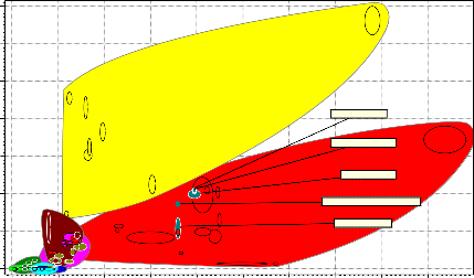
The major criterion in the development of the fuel fired crucible furnace was to ensure minimum heat losses from the furnace to the surrounding. Adequate insulation was provided to achieve this and also to optimize the furnace efficiency. The rate of heat transfer across the crucible furnace depends on the thermal properties of the refractory material and the interface characteristic.
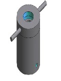
Figure 1: Geometric View of furnace
IJSER © 2014 http://www.ijser.org
International Journal of Scientific & Engineering Research, Volume 5, Issue 7, July-2014 619
ISSN 2229-5518
dry, rigid and firm monolithic structure of refractory lining. The base of the crucible lining was molded in a platform pattern to give a seat for the crucible pot.
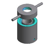
Figure 2: Exploded view showing part of furnace
A 5.0 mm mild steel sheet of dimension 600 mm x
700 mm was cut using cutting machine and rolled
to shape using rolling machine to dimension 580
mm x 615 mm, this dimension allows tolerance of 3 mm x 5 mm. The rolled plate was joined at the edges by welding using electric arc machine to form a cylindrical shape which serves has the body of the cylinder. The tolerance was cut away to give the actual dimension of 577 mm x 610 mm. The base of the furnace was made from the mild steel sheet that was cut into a circular shape of diameter
580 mm; the circular plate was welded to the body
of the furnace to give a solid base. A crucible cover
of 577 mm x 150 mm was fabricated from the mild steel plate and a hole of 250 mm was fabricated on the cover to serve as an exhaust for the fumes and gases. Handles were attached to the crucible cover to allow for easy removal of the cover from the body of the furnace during loading of charges into the furnace and during removal of crucible pot from the furnace.
The kaolin refractory materials were grinded and sieved using sieve of mesh 300 um to have fine particles of the refractory, the kaolin materials were mixed and poured in to the furnace shell and rammed in the elastic mix while it is wet to produce a homogenous structure, this was done to give a bulk density in order to give volume stability and reduced the volume of open pores into which liquid can penetrate. The ramming and the filling of the kaolin into the furnace shell were done till the thickness of 70 mm was reached. The lining of the furnace was fired in order to give a
The crucible pot is a standard part but due to the cost of procurement of the pot most of the small
scale and medium scale industries may not be able to afford it. Therefore an alternative which was the use of compressor boiler plate and refrigerator condenser’s cylinders, made of pressed alloy steel was selected. The crucible pot was made of boiler plant pressed alloy steel, the height of the crucible pot is 500 mm.
. RESULTS AND DISCUSSION
The bubble charts for the material selection of the furnace shell were shown in Figures 5, 6 and 7 and that of material selection for furnace lining were shown in Figures 8 to 12. These results were generated using GRANTA software. The software plotted the properties of each unit of the furnace in form of bubbles and the candidate material where selected from the bulk of materials suggested by the software. The function, objectives and constraints of the part or the unit to be designed must be well known, the material properties to be selected would be determined base on these fundamental parameters.
As it can be seen from bubble chart graphs shown in Figures 5 to 7 different properties were plotted against each other using GRANTA software. The properties were arrived at as the result of the function, objective and constraint that the furnace shell would perform.
The plot of bubble Figure 5; the plot of young modulus against price, with these properties we were trying to select a candidate material with moderate strength at low cost. Since the part of the objectives of the furnace shell is to have a good strength that can carry its own weight and that of
IJSER © 2014 http://www.ijser.org
International Journal of Scientific & Engineering Research, Volume 5, Issue 7, July-2014 620
ISSN 2229-5518
the refractory linings and crucible pot and our constraint is cost, we will need a candidate
material that is relatively cheap and at the same time has the required strength and durable. Going by these properties the following materials are
suggested candidate materials: medium carbon steel, low alloy steel, high carbon steel, low carbon
steel and stainless steel. These candidate materials have a moderate young modulus above 2x10⁵
N/mm2 and the price is lower
7e11
6e11
Low alloy steel
Medium carbon steel
High carbon steel
5e11
Low carbon steel
4e11
3e11
Stainless steel
2e11
1e11
0
0 2000 4000 6000 8000 10000 12000 14000 16000 18000 20000
Price (NGN/kg)
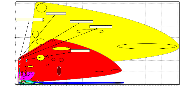
Figure 5: Bubble Chart of Young’s Modulus versus Cost Price
IJSER © 2014 http://www.ijser.org
International Journal of Scientific & Engineering Research, Volume 5, Issue 7, July-2014 621
ISSN 2229-5518
3. 5e11
3e11
2. 5e11
Low alloy steel
2e11
High carbon steel
1. 5e11
Stainless steel
1e11
Cast iron, ductile (nodular)
5e10
Cast iron, gray
0
1 1. 5 2 2. 5 3 3. 5 4 4. 5 5
Weldability
Figure 6: Bubble Chart of Young’s Modulus versus W eldability
7e11
6e11
5e11
4e11
Low alloy steel
Low carbon steel
3e11
Stainless steel
2e11
Cast iron, ductile (nodular)
1e11
Cast iron, gray
0
0 2000 4000 6000 8000 10000 12000 14000 16000 18000
Density (kg/m^3)
Figure 7: Bubble Chart of Young’s Modulus versus Density
than 1000 NGN except for stainless steel of young modulus of 2x10⁵ N/mm2 and the price more than
1000 NGN. From this result it could be seen that the stainless steel although non corroding has a lower strength compared to the other candidate materials and is not economical in terms of cost. Cast iron ductile (nodular) and cast iron gray were cheaper they were not considered because of their young modulus about 1.75x10⁵ N/mm2 and 1.0x10⁵
N/mm2 respectively.
Figure 6 is the plot of young modulus and weldability. The young modulus determines the strength of the furnace shell and the weldability
determines the formability/processability of the candidate material to shape. The objective of the
furnace shell was that the candidate material to be chosen must be able to retain its strength when formed. The process route chosen for the fabrication of the furnace shell was welding; therefore weldability of the candidate material to be chosen must be given consideration. Going by these properties the following materials are suggested candidate materials: medium carbon steel, low alloy steel, high carbon steel, low carbon steel and stainless steel. These candidate materials have weldability factor of 5 which is very high and
IJSER © 2014 http://www.ijser.org
International Journal of Scientific & Engineering Research, Volume 5, Issue 7, July-2014 622
ISSN 2229-5518
the young modulus above 2x10⁵ N/mm2 except for stainless steel with 2x10⁵ N/mm2. Cast iron ductile
(nodular) and cast iron gray were not considered because very low young modulus and weldability of 1.
Figure 7 is the plot of young modulus against density. The candidate material to be selected must be strong and has a moderate density to reduce the weight and bulkiness of the crucible furnace. Polymeric materials would have been the suitable candidate material if to go by the lightness in density but due to their low young modulus they might not be able to support the weight of the refractory lining, the crucible pot and that of its own. Aluminum with a low density could also have been a preferred candidate material but due the low young modulus it was not used for this purpose. Cast iron ductile (nodular) and cast iron gray were also considered but they have low density of 7200 kg/m3 as compared to 8000 kg/m3 of medium carbon steel, low alloy steel, high carbon steel, low carbon steel and stainless steel but due to their low young modulus they were not used as candidate material. The candidate materials considered for this function were medium carbon steel, low alloy steel, high carbon steel, low carbon steel and stainless steel.
With the following estimated desired properties and their successive plots. It was inferred that Low carbon steel (typically Mild steel) would be the most suitable material. Stainless steel would have been the best but it is highly expensive. Although medium carbon steel, low alloy steel, high carbon
steel has good strength going by their young modulus which was above 2x10⁵ N/mm2, they also
possessed good weldability of 5 and have moderate density of 8000 kg/m3 yet they were not considered because of formability to shape during processing route i.e. the forming of the furnace body involved rolling to shape to give a cylindrical structure which would be difficult to achieve with medium carbon, low alloy and high carbon steel due to their hardness as a result of alloying in low alloy steel and percentage of carbon in medium and high carbon steel.
The furnace shell is the outer unit of the fuel fired crucible furnace and it was fabricated from a 5.0 mm mild steel plate. It sheltered the refractory linings, the flame gap and the crucible pot for the melting of the copper metal. The furnace shell required a material that is strong, durable and must be able to withstand its own weight, the refractory lining and that of crucible pot. Considering all these properties coupled with material properties, availability and cost, mild steel plate of thickness 5 mm (AISI 1018) according to American Society for Testing having about 0.18 % carbon, was used for the construction of the furnace outer shell because of the required rigidity, strength, fabricability, availability, ability to withstand and retain its high strength even when rolled to shape from sheet.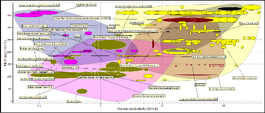
Figure 8 : Bubble Chart of melting temperature versus Thermal expansion coefficient
IJSER © 2014 http://www.ijser.org
International Journal of Scientific & Engineering Research, Volume 5, Issue 7, July-2014 623
ISSN 2229-5518
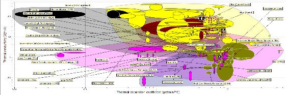
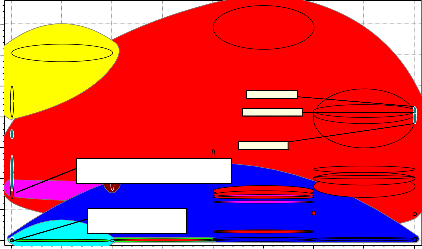
Figure 9: bubble Chart of Thermal conductivity and thermal expansion coefficient
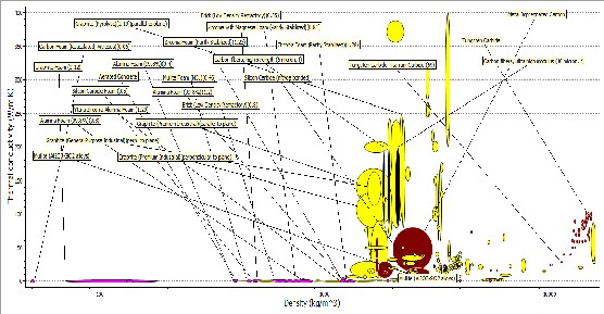
Figure 10: Bubble Cart Thermal conductivities versus Density
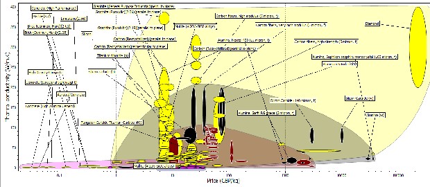
Figure 11: Bubble chart of Thermal conductivities against Price
IJSER © 2014 http://www.ijser.org
International Journal of Scientific & Engineering Research, Volume 5, Issue 7, July-2014 624
ISSN 2229-5518
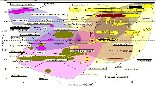
Figure 12: Bubble chart of melting point versus Thermal conductivity
As it can be seen from bubble chart graphs shown in Figures 8 to 12, different properties were plotted against each other using GRANTA software. The properties were arrived at as the result of the function, objective and constraint that the furnace lining would perform.
The plot of Figure 8 shows the plot of melting point against thermal expansion coefficient, with these properties we were trying to select a candidate material with high melting temperature which would be high enough to withstand the working temperature of furnace 1200 0C and low thermal expansion coefficient. Since the part of objectives of the refractory lining is to have a refractory fusion at working temperature so as to prevent failure during service and also the refractory linings should be able to withstand thermal stress as a result of varying temperature. The constraints were cost and availability, the refractory linings must be cheap and readily available locally. Going by these properties the following materials suggest candidate materials were: Boron Carbide, Tungsten Carbide, Tungsten alloys, Zirconia, Silica Cardide, Aluminum nitride
ceramic foams, silicon, mullite (kaolin) and alumina. Alumina and mullite (kaolin) were considered because the melting temperatures were within the range of above 1500 0C to 2000 0C since the working temperature of the furnace would be around 1200 0C and also they have low thermal expansion coefficient. Although the other listed materials have better melting temperatures the design of the furnace may not necessitate the use such high temperature in furnace.
The plot of Figure 9 shows the plot of thermal conductivity against thermal expansion coefficient; the materials to be selected must have low thermal conductivity and it must have low thermal coefficient of expansion. Going by the chart silicon, silicon carbide, tungsten carbide, Alumina, mullite (kaolin) and Boron carbide were considered. Alumina and mullite (kaolin) were selected as candidate materials because they have low thermal expansion coefficient and the thermal conductivities were 6 W/mK and 4 W/mk.
The plot of Figure 10 shows the plot of thermal conductivities against density, with these properties we were considering materials with low thermal conductivity and low density. The low density material was required in order to reduce
IJSER © 2014 http://www.ijser.org
International Journal of Scientific & Engineering Research, Volume 5, Issue 7, July-2014 625
ISSN 2229-5518
the bulkiness and weight of the furnace. From the
Fig. 4.6, the following candidate materials were
suggested; silicon nitride, alumina, boron carbide, zirconia, alumina nitride and silicon. From the chart, silicon nitride, mullite (Kaolin), alumina, boron carbide, zicronia, alumina nitride and silicon have thermal conductivities of 26, 4, 6, 80, 5, 200 and 140 W/mK and their densities were 3400, 4000,
2600, 6000, 3700 and 2200 Kg/m3. It could be seen
that mullite has the lowest thermal conductivity and alumina nitride has the highest value which affected its use in the furnace. The density of zirconia made it too heavy to be considered has a candidate material. Mullite and Alumina were considered here based on their properties.
The plot of Figure 11 shows the plot of thermal conductivity against price, with these properties we were considering a suitable candidate material with low thermal conductivity and it would be relatively cheap. From the chart materials like silicon, silicon carbide, tungsten carbide, alumina, boron carbide, silicon nitride, zirconia, kaolin and alumina nitride were considered. It could be seen that though the silicon, silicon carbide, alumina and kaolin (mullite) were cheap compared to boron carbide, silicon nitride, aluminum nitride. Silicon, Silicon carbide, Tungsten Carbide has very high thermal conductivities when compared to alumina, mullite (kaolin) and zirconia.
The plot of Figure 12 shows the plot of melting point against thermal conductivity, with these properties we were considering a suitable candidate material with high melting temperature and with low thermal conductivity. From the chart materials like tungsten carbide, zircon, silicon nitride, silicon carbide, kaolin alumina and silicon were considered. It could be seen that tungsten carbide, zircona, silicon nitride has high melting temperature and low thermal conductivities. Alumina, mullite (kaolin) has relatively high melting temperature but the thermal conductivities were low.
In terms of availability, an author [15] has reported that kaolin mullite is located in commercial quantity at Ukpor, Ozubulu, Enugu, Kwi, and Otukpo (all in Nigeria), to mention but a few. They are lightweight, low in thermal conductivity, and
yet sufficiently resistant to temperature to be used successfully on the hot side of the furnace wall,
thus permitting thin walls of low thermal conductivity and low heat content. The low heat content is particularly valuable in saving fuel and time on heating up, allows rapid changes in temperature to be made, and permits rapid cooling [16]. Considering the above factors kaolin refractory was used in this work to minimize the production cost and to derive the maximum operating requirements of high refractoriness- resistance to fusion at working temperature, resistance to thermal fatigue, low thermal conductivity to prevent heat loss from the furnace, impermeability to gases, high resistance to abrasion and good thermal resistance for adequate insulation [13].
Kaolin refractory was used for the lining of the furnace to reduce and prevent heat loss in the crucible furnace. The selection was based on the following pre-determined factors; namely, environmental condition, furnace requirements, cost, availability and estimated service life.
The material selection for the units in the furnace has solved the problem of heat retention capability of the furnace which is a major problem in the local foundry. GRANTA® software has really helped in the selection of appropriate candidate material for each component part of the furnace unit and there is no doubt that the stress involved in old method of material selection has completely been eradicated.
The technique and the process involved in the
development and fabrication of the furnace were simple making the production of such furnace easy to learn for small scale industry.
In conclusion the locally available materials in our
country are adequate for the design and
construction of a fuel-fired crucible furnace
[1]Atanda, P. O. (2009) Development of Integrated salt bath isothermal heat treatment furnace unit for Austempering Ductile Iron. Ph.D. Thesis Project. Obafemi OAU Ile Ife Nigeria.
IJSER © 2014 http://www.ijser.org
International Journal of Scientific & Engineering Research, Volume 5, Issue 7, July-2014 626
ISSN 2229-5518
[2]Gilchrist, J. D (1997), ‘Fuels, Furnaces and Refractories’,
Pergamon Press.
[3]Holman, J.P (1974), ‘Heat Transfer’ 3rd Ed. McGraw Hill
Book Company, Toronto.
[4]Schack, A (1965), ‘Industrial Heat Transfer’ 3rd Ed. McGraw Hill Book Company, New York.
[5]Trinks W. (1967) ‘Industrial Furnaces’ Vol.1 and 2. John
Wiley and Sons Inc; New York.
[6]Davies, D.J and Oelmann, L.A (1983) ‘The Structure, Properties and Heat treatment of Metal’; Pitman Book Ltd, London.
[7]Callister, W.D. (1978) Fundamentals of Materials Science
and Engineering, 2nd ed. Wiley & Sons.
[8]Chung, D.D.L. (2009) ‘Composite Materials Science an d Applications’2nd ed. State University of New York, Buffalo Dept. Mechanical & Aerospace Engineering NY 14260–4400, Buffalo.
[9]GRANTA R&D, Inc. (2009)". http://www.granta.com.
Retrieved 2009-10-26.
[10]Degarmo E.P, Black J.T, and Ronald A. K. (1997),
‘Materials and Processes in Manufacturing’ 8th ed., Prentice
Hall of India Private Ltd, New Delhi-110001.
[11]Gupta, O. P. (1997) ‘Elements of Fuels, Furnaces and
Refractories’ Khanna Publishers, India.
[12]John, V. (1992), ‘Introduction to Engineering Materials’
3rd Ed. Macmillan London.
[13]Norton, F. H (1968), ‘Refractories’ 4th Ed., McGraw Hill
Book Company, New York.
[14]Chesti, A. R. (1986) ‘Refractories manufacture, properties, and applications’, Delhi, Prentice-Hall of India Private Limited.
[15]John, M. U., (2003), ‘An investigation into the use of local clay as high temperature insulator for electric cookers' , PhD thesis, Minna, Federal University of Technology, Minna, Nigeria, 2003.
[16]Avallone E. A. and Baumeister III T. (1996), Marks standard handbook for mechanical engineers, New York, Mc Graw-Hill International Edition.
IJSER © 2014 http://www.ijser.org