The research paper published by IJSER journal is about Multi-band Ladder-shape Microstrip Patch Antenna 1
ISSN 2229-5518
Venkata Raviteja.K1, Dr.K.S.N Murthy2, I.Govardhani3, M.Venkata Narayana4
Abstract: Now a day’s broad-band antennas gaining importance because of their usage at high frequencies and ability to achieve high speed data communication. Microstrip patch antennas are of such type and are increasing in popularity for use in wireless applications. They are widely used because of their several advantages such as light weight, low volume, low fabrication cost and compatability with integrated circuit technology operating in multiple bands with multiple polarizations. Here we are using ladder shaped microstrip patch antenna with which it achieves dual band of frequencies. Significant reduction of antenna size can be realized when the H-shaped patch is used instead of the conventional rectangular microstrip patch antenna. By using the proposed antenna we can simulate return loss, gain, axial ratio and radiation patterns at these dual band of frequencies achieving circular polarization.
Key Terms- Microstrip patch antenna, Ladder-shape, gain, return loss
—————————— ——————————
1.Introduction:
The W band of the microwave part of the electromagnetic spectrum ranges from 75 to 110 GHz. It is used for satellite communications, millimeter wave radar research, military radar targeting and tracking applications, and some non-military applications. In terms of communications capability, W -band offers high data rate throughput when used at high altitudes and in space. Microstrip or patch antennas are becoming increasingly useful because they can be printed directly onto a circuit board. This type of antennas are becoming widespread usage within the mobile phone market.
In this paper ladder shaped antenna is designed with single polarization and dual frequency using coaxial feed. Dual frequency operations can be realized by exciting the microstrip patch antenna using a single feed or dual feed. The proposed antenna works in w band ranging from 75-110 GHz. It is well suited for satellite communications and millimeter wave radar applications.
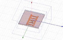
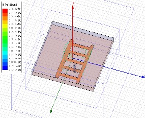
The proposed structure of the antenna is simulated on an Rogers RT/duroid 5880(tm) substrate with dielectric constant of 2.2 and a loss tangent of 0.0009 and simulated at dual frequencies of 89 GHz and 92 GHz frequencies respectively. ‘L’ is the resonant length of patch which is
2cm, width of the patch is 0.5cm and height of the dielectric
substrate should be in between 0.003 λ0 and 0.05λ0. We have taken 0.02 times of λ0. As 50Ω coaxial cables are used normally, feed point is taken where 50Ω resistance occurs.
Fig1: Antenna Model.
HFSS is a high-performance full-wave electromagnetic (EM) field simulator for arbitrary 3D volumetric passive device modeling that takes advantage of the familiar Microsoft Windows graphical user interface. It integrates simulation, visualization, solid modeling, and automation in an easy-to-learn environment where solutions to your 3D EM problems are quickly and accurately obtained. Ansoft HFSS employs the Finite Element Method (FEM), adaptive meshing, and brilliant graphics to give an unparalleled performance and insight to all of our 3D EM problems. Ansoft HFSS can be used to calculate parameters such as S- Parameters, Resonant Frequency and Fields.
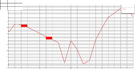
It is a measure of the reflected energy from a transmitted
signal which is commonly expressed in positive dB's. The larger the value the lesser is the energy that is reflected.
IJSER © 2012 http://www.ijser.org
The research paper published by IJSER journal is about Multi-band Ladder-shape Microstrip Patch Antenna 2
ISSN 2229-5518
The designed antenna is simulated using HFSS software. The results obtained are mentioned below.
dB is obtained.
AnNsaomfteCorporaXtion Y
Return Loss
Patch_Antenna_ADKv1
m-71.00 89.0000 -17.1447 m2 92.0000 -17.3230
-8.00
-9.00
-10.00
-11.00
-12.00
-13.00
Curve Inf o dB(St(1,1))
Setup1 : Sw eep1
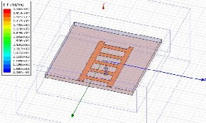
An electric field can be visualized by drawing field lines, which indicates both magnitude and direction of the field. Field lines start on positive charge and end on negative
charge. The direction of the field line at a point is the
-14.00
-15.00
-16.00
-17.00
-18.00
m1 m2
80.00 85.00 90.00 95.00 100.00
Freq [GHz]
direction of the field at that point. The relative magnitude
of the electric field is proportional to the density of the field lines.
Fig2: Return loss
A return loss of -17.1447 dB at 89 GHz and -17.3230 at 92
GHz is obtained.
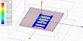
Fig5: E-Field pattern.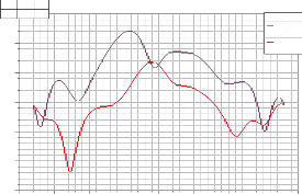
AnNsaomfteCorporatXion Y
ff_2D_GainTotal
Patch_Antenna_ADKv1
1m01.00 -42.0000 7.0437
m1
5.00
0.00
-5.00
-10.00
-15.00
Curve Info dB(GainTotal)
Setup1 : LastAdaptive
dB(GainTotal)_1
Setup1 : LastAdaptive
In the case of linearly polarized antenna, this is the plane containing the magnetic field vector and the direction of maximum radiation. The magnetic field or ‚H‛ plane lies at a right angle to the ‚E‛ plane. For a vertically-polarized antenna, the H-plane usually coincides with the
horizontal/azimuth plane. For a horizontally-polarized
-20.00
-200.00 -150.00 -100.00 -50.00 0.00 50.00 100.00 150.00 200.00
Theta [deg]
Fig3: 2-D Gain.
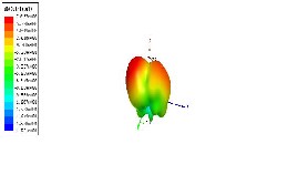
Fig4: 3-D Gain.
antenna, the H-plane usually coincides with the vertical/elevation plane.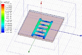
Fig6: H-Field pattern.
For the designed antenna model a 2D and 3D gain of 7.0437
IJSER © 2012 http://www.ijser.org
The research paper published by IJSER journal is about Multi-band Ladder-shape Microstrip Patch Antenna 3
ISSN 2229-5518
The field equations of Einstein Cartan Evans (ECE) are used
to develop the concept of the static electric field as a vector boson with spin indices −1, 0, +1, which occur in addition to the vector character of the electric field. The existence of the
electric vector boson in physics is inferred directly from
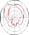
The radiation pattern or antenna pattern describes the
relative strength of the radiated field in various directions from the antenna at a constant distance.
Cartan geometry, using the concept of a spinning space-
time that defines the electromagnetic field. When the
Ansoft Corporation
-30
Radiation Pattern 2
0
30
4.00
Patch_Antenna_ADKv1
![]()
Curve Inf o dB(GainTotal)
Setup1 : LastAdaptive
electromagnetic field is independent of the gravitational field the spin connection is dual to the tetrad, producing a set of equations with which we can define the electric vector boson. Angular momentum theory is used to
develop the basic concept.
-90
-60
-120
-150
-2.00
-8.00
-14.00
150
60
90
120
Phi='0deg'
dB(GainTotal) Setup1 : LastAdaptive Phi='90.0000000000002deg'
-180
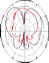
Fig9: Radiation pattern of Gain total.
Ansoft Corporation
Radiation Pattern 2
Patch_Antenna_ADKv1
-60
-30
0
30
3.00
-4.00
60
-11.00
-18.00
![]()
Curve Inf o dB(GainTheta)
Setup1 : LastAdaptive
Phi='0deg'
dB(GainTheta) Setup1 : LastAdaptive Phi='90.0000000000002deg'
Fig7: Vector E-Field pattern.
-90 90
-120
120
-150
150
-180
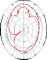
Fig10: Radiation pattern of Gain in Theta direction.
Ansoft Corporation
Radiation Pattern 3
![]()
Patch_Antenna_ADKv1
Fig8: Vector H-Field pattern.
-90
-60
-120
-30
-150
0
-4.00
-18.00
-32.00
-46.00
-180
30
150
60
90
120
Curve Info
dB(GainPhi) Setup1 : LastAdaptive Phi='0deg'
dB(GainPhi) Setup1 : LastAdaptive Phi='90.0000000000002deg'
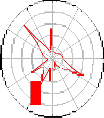
Fig11: Radiation pattern of Gain in Phi direction.
IJSER © 2012 http://www.ijser.org
The research paper published by IJSER journal is about Multi-band Ladder-shape Microstrip Patch Antenna 4
ISSN 2229-5518
Ansoft Corporation
-90
-60
-120
-30
Radiation Pattern 5
0
30
56.00
42.00
28.00
14.00
60
90
120
Patch_Antenna_ADKv1
![]()
Curve Inf o dB(AxialRatioValue)
Setup1 : LastAdaptive

[4]. Phased Array Antenna for Millimeter Wave Radar in W-band using Liquid Crystal Substrate International journal of Emerging trends in computing Vol. 2, No.12 , December 2011
I.Govardhani,K.Rajkamal,M.VenkataNarayana, S.Venkateswarlu
Fig12: Axial Ratio.
-150
-180
150
[5] D.M.Pozzar "Microstrip Antenna Coupled t o Microstripline," Electron Lett., vol. 21, no.2, pp. 49-50, January 1995.
Axial Ratio is the ratio of peak value in the major lobe
direction to peak value in the minor lobe direction.
Thus the proposed antenna works at dual frequency bands of 89 GHz and 92 GHz which is in the W band range. It is well suited for satellite communications, millimeter wave radar applications.
We would like to express our sincere thanks to the department of ECE and management of KL University for their continuous support and encouragement in completion of this work.
[1] Ramesh Garg, Prakash Bartia, Inder Bhal and Apsiak Ittipiboon, "Microstrip Antenna Design Hand Book," Artech House, Norwood, MA, 200 I .
[2]Comparative Analysis of Exponentially Shaped Microstrip-Fed Planar Monopole Antenna With and Without Notch, International journal of Emerging trends in computing Vol. 2, No.11 , November 2011
M. Venkata Narayana1, I.Govadhani2, K.P.Sai Kumar, K. Pushpa Rupavathi.
[3].Design of coaxial fed Microstrip patch antenna for
2.4Ghz. International journal of Emerging trends in computing Vol. 2, No.12 , December 2011
Govardhani.Immadi,M.S.R.S.Tejaswi,M.VenkataNarayana, N.Anil Babu, G.Anupama, K.Venkata Ravi teja.
[6] K.-L. Wong and J.Y. Sze, "Dual frequency slotted rectangular microstrip antenna", Electron Lett 34 (1998).
1368-1370
[7] J.S. Row and K.W. Lin, "low profile design of dual- frequency and dual-polarised triangular microstrip antennas", Electron Lett 40 (2004), 153-154.
[8] J.s. Row, "Dual-frequency dual-polarized microstrip antenna fed by an inclined slot", Microwave Opt Technology Lett 41 (2004), 512-514
[9] J.Y. Jan, "Low-profile dual-frequency circular microstrip antenna for dual ISM bands", Electron Lett (2001), 999-1000.
[10] G.S. Binoy, CK Aanandan, P. Mohanan, K. Vasudevan, and K.G. Nair, "Single feed dual Frequency dual polarized slotted square microstrip antenna, Microwave Opt Technol Lett 25 (2000).395-397.
[11] Che-Wei Suo Jeen-Sheen Row, A single-feed dual frequecy dual polarized microstrip antenna Vol. 47, No. 2,
2005
[12] Zeland Software Inc., "IE3D Electromagnetic
Simulation and optimization package, Version 14.2".
[13] J. R. James, P. S. Hall, and C. Wood, Microstrip Antenna
Theory and Design. London, U.K.: Peregrinus, 1981.
[14]V.Palanisamy and R. Gary,Rectangular ring and H shaped microstrip antennas-alternatives to rectangular patch antennas�, IEE Electron. Lett, Vol.21, no.19 , pp.874~876, 1985
[15]Dilbagh Singh, Christos Kalialakis, Peter Gardner,‛ Small H-Shaped Antennas for MMIC Applications‛, IEEE Transactions on antennas and propagation, Vol.48, No,7
,pp.1134-1141,July2000
IJSER © 2012 http://www.ijser.org
The research paper published by IJSER journal is about Multi-band Ladder-shape Microstrip Patch Antenna 5
ISSN 2229-5518
[16]M.EI Yazidi, M. Himdi and J. P. Daniel,Transmission line analysis of nonlinear slot coupled microstrip antenna�, Electronics Letters,Vol.28 No.15,16h July 1992
[17]MITSUO MAKIMOTO and SADAHIKO YAMOSHITA,Bandpass Filters Using Parallel Coupled Stripline Stepped Impedance Resonators � , IEEE Transactions on microwave theory and techniques, Vol, MTT-28, No.12 , December,1980
[18]Jaume Auguera�Lluis Boada�Carles Puente�Carmen Boarja�Jordi Soler��Stacked H-Shaped Microstrip patch Antenna ,IEEE TRANSACTIONS ON ANTENNAS AND PROPAGATION,Vol.52,No,4,April,2004
[19]Y. Qin, S. Gao, A. Sambell, E. Korolkiewicz and M. Elsdon,‛ Broadband patch antenna with ring slot coupling‛,
Electronics Letters,Vol.40 No.1,8th January 2004
[20] J. P. Kim, W. S. Park ‚Analysis and network modeling of an aperture-coupled microstrip patch antenna,‛ IEEE Trans. Antennas Propagat., vol. 49, pp. 849-854, June 2001.
[21] J. P. Kim, W. S. Park ‚An improved network modeling of slot-coupled microstrip lines,‛ IEEE Trans. Microwave Theory Tech., vol. 46, pp. 1484-1491, October 1998.
[22] D. G-Kurup, A. Rydberg, and M. Himdi,
‚Transmission line model for field distribution in
microstrip line fed H-slots,‛ Electron. Lett., vol. 37, no. 14, July 2001.
1893.


IJSER © 2012 http://www.ijser.org
The research paper published by IJSER journal is about Multi-band Ladder-shape Microstrip Patch Antenna 6
ISSN 2229-5518
IJSER © 2012 http://www.ijser.org