International Journal of Scientific & Engineering Research, Volume 4, Issue 12, December-2013 1855
ISSN 2229-5518
MEMS based Capacitive Pressure Sensor Simulation for Healthcare and Biomedical Applications
Shivam Kohli, Anish Saini, Ajesh.J.Pillai
Abstract-This paper presents the design and characterization of a simulation of a capacitive blood pressure for healthcare and biomedical applications. Vital sign measurement and assessment are important components of the review of systems in a physical therapy examination for individuals with and without documented cardiopulmonary disease. The measurement of blood pressure based on the blood flow gives the therapist information regarding the patient’s baseline cardiovascular status, response to exercise/activity, and guides exercise prescription. Accurate measurement of blood pressure is critical for making appropriate clinical decisions especially if physical therapists or doctors wish to play an important role as primary health care providers. The purpose of this paper is to present a stimulated structure used for measuring accurate pressure of blood flow through a vein or an
artery using basic known technology of microelectromechanical (MEMS) systems along with the simulation of design and bridge the gap between turbulence in blood vessels and resulting forces that may be relevant to diseases of the blood vessels
Index Terms-Microelectromechanical systems, Capacitive pressure sensor, pressure measurement, finite element method, biomedical application
— — — — — — — — — — — — — — — — — — — —
1 INTRODUCTION
promising technical application of micro
electomechanical system (MEMS) technology
a vein or an artery using deflection of a diaphragm
and measurement of the deflection using capacitor
IJSER
based pressure sensors arises in the field of
biomedical sensors and instrumentation. Blood
pressure and rate of blood flow are one of the most
important parameters in the field of biomedical and instrumentation. They are one of the most important parameters to indicate the health and wellbeing of a patient. Extreme fluctuations in the level of blood momentum cause cardiovascular disease which remain the biggest cause of deaths worldwide. Blood pressure (BP) is the force of circulating blood against the walls of arteries and blood vessels [1]. It is one of the measurements used in evaluating vital signs. Vital sign measurement and assessment are important components of the review of systems in a physical therapy examination for individuals. The measurement of blood pressure based on blood flow gives the therapist information regarding the patient’s baseline cardiovascular status, response to exercise/activity, and guides exercise prescription. Accurate measurement of blood pressure is critical for making appropriate clinical decisions especially if physical therapists or doctors wish to play an important role as primary health care providers. The purpose of this paper is to present a stimulated structure used for measuring accurate pressure of blood flow through
to give the output.[1] These MEMS based pressure
sensor can be used for healthcare and biomedical
applications. The designed sensor is wrapped
along the periphery of the main artery. The arterial blood pressure transmited via the fluid deflects the flexible diaphragm of the pressure sensor. The deflections can be measured using various detection mechanisms such as optical, piezoresistive, piezoelectric and capacitive methods and suitable output is given. The following figure (1) gives the basic pressure variation in the human body. [12]
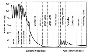
Fig 1: Pressure Variation in the Human Body
2 Model Definition
In this example the flow channel is taken out to be
an artery and the sensors are basic diaphragms or
IJSER © 2013 http://www.ijser.org
International Journal of Scientific & Engineering Research, Volume 4, Issue 12, December-2013 1856
ISSN 2229-5518
basic elastic strip made of a certain material that
bends when a certain amount of load acts on it and
gives output according to its displacement. The material strips are placed at the around the surface of the tube structure where they give out the desired output of the fluid passing through by measuring its displacement according to pressure acting on it [1][8].
The fluid is a blood with a density = 1060 kg/ m and dynamic viscosity = 0.005 Ns/ m . The artery or vein basic material properties consists of a flexible material with density = 960 kg/ m . Neo- Hookean hyper elastic behavior: the coefficient µ equals 6.20106 N/m2, while the bulk modulus
equals 20 µ and corresponds to a value for
Poisson’s ratio, ν of 0.45. An equivalent elastic
modulus equals 1.0107 N/ m [7].
2.1 MODEL ANALYSIS
Fluid dynamics analysis -Here the model solves
that arise from applying Newton's second law to fluid motion, together with the assumption that the
stress in the fluid is the sum of a diffusing viscous term (proportional to the gradient of velocity) and a pressure term - hence describing viscous flow. The equations are useful because they describe the physics of many things of academic and economic interest. The major two interactions that takes place in the model are [8]:
(Fluid–rigid-body interaction) In some circumstances, especially when the structure is embedded in a fluid and its deformations are small compared with the displacements and rotations of its center of gravity; it is justified to idealize the structure as a rigid body resting on a system consisting of springs and dashpots.
(Free surface and structure interaction) The
above discussion of the coupling problem only applies to those portions of the structure that are
always submerged during the calculation. As a
IJSER
the Navier-Stokes equations in the blood domain.
At each surface where the model brings a tube to an abrupt end, it represents the load with a known pressure distribution.
Mechanical analysis -this analysis is nonlinear due to the assumption of a large displacement and the constitutive behavior of the materials (the model describes the response of the sensor (diaphragms) and tube with a hyper elastic law similar to those for rubber components). Only the domains related to
the biological tissues are active in this analysis. The
matter of fact, there may exist portions of the
structure, which only come into contact with the
fluid sometime after the calculation begins. This is, for instance, the case for structural parts above a fluid-free surface. [7]
The ALE differential form [11] of the conservation eq uati on s for mass, momentum, and energy are readily obtained from the corresponding Eulerian forms
d ρ = ∂ρ +υ ∇ρ = −υ ∇ρ
model represents the load with the total stress
distribution it computes during the fluid-dynamics


Mass:
. .
dt ∂t
analysis. The displacement of the diaphragms
(sensors) due to amount of pressure on them is


Momentum: ρ dυ = ρ( ∂υ + (υ.∇)υ) = ∇.σ + ρb dt ∂t
used to calculate the velocity of the blood flow. [1]
And these analysis are done using Arbitrary-
Energy:
= ∇.(σ .υ) +υ.ρb
= ∇.(σ .υ) +υ.ρb
Lagrangian-Eulerian general research applications (ALEGRA) which are codes regarding formulation on an unstructured mesh, allowing one to designate whether material should flow through a stationary mesh(pure Eulerian). Whether the mesh should move with the material (pure Lagrangian), or whether the mesh should be allowed to move independently of the material motion (arbitrary). And Navier-Stokes equations which are equations
Where ρ is the mass density, v is the material velocity vector, σ denotes the Cauchy stress tensor, b is the specific body force vector, and E is the specific total energy. Only mechanical energies are considered in the above form of the energy equation. Note that the stress term in the same equation can be rewritten in the form
IJSER © 2013 http://www.ijser.org
International Journal of Scientific & Engineering Research, Volume 4, Issue 12, December-2013 1857
ISSN 2229-5518
∇.(σ .υ) =
∂(σ i υ j )

∂x

= ∂σ ij υ
∂x
j + σ i
∂υ j

∂x
i i i
= (∇.σ ).υ + σ : ∇υ
Where ∇v is the spatial velocity gradient. All one
has to do to obtain the ALE form of the above
Conservation equations is to replace in the various convective terms, the material velocity v with the convective velocity c = v − ˆv. The result is
(a) (b)
 (c)
(c)
Mass:
Momentum:

∂ρ + c.∇ρ = −ρ∇.υ
∂t

ρ ( ∂υ + (c.∇)υ) = ∇.σ + ρb
∂t
Fig 2: (a) represents normal blood flow in artery (b) represents low blood pressure in an artery (c) represents high blood pressure in an artery.

Total Energy: ρ( ∂E + c.∇E) = ∇.(σ .υ) +υ.ρb
∂t
2.3 Mechanics of Diaphragm
2.2 Morphology of blood vessels
The pumping action of heart consists of two processes: ventricular contraction phase when blood is forced out of the heart is known as systole, the ventricular relaxation or filling phase when blood is received into heart is termed as diastole. The blood vessels form a closed network that carries the blood away from the heart and back. This vessel network consists of arteries, arterioles,
capillaries, venules and veins. The arteries are
large vessels that are very strong and elastic and they deform as the blood flows away from the heart under high pressure. The arterial walls consist of three distinct layers or tunics which are termed as:
Tunica Intima: it consists of a layer of a simple
squamous epithelium called endothelium that rests on a connective tissue membrane that is rich in elastic and collagenous fibers.
Tunica Media: it makes up the bulk of the arterial
wall. It has a thick layer of connective tissue which gives artery a tough elasticity to withstand the blood pressure force and at the same time stretch in order to accommodate the sudden increase of blood volume that accompanies the opening of the heart valve due to ventricular contraction of the cardiac muscle.
Tunica Adventitia: it is a thin layer and mainly
consists of connective tissue with elastic collagenous fibers. This layer ataches the artery to the surrounding tissues.
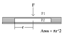
Fig 3: Simple Pressure Sensor Diaphragm
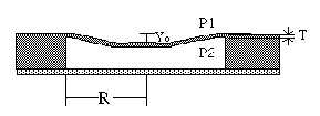
Fig 4: Deflection in a Diaphragm
Pressure sensors all operate on the basis of the same principle: the detection of a physical force which arises due to pressure. For example, if a diaphragm separates two regions with different pressures on either side, there will be a physical force on the diaphragm (see Fig. 3 and 4) given by:
Force = (P1 - P2) (Diaphragm area)
The force is directed from the high pressure region to the low-pressure region. In order to measure this force, we may measure the deflection of the
IJSER © 2013 http://www.ijser.org
International Journal of Scientific & Engineering Research, Volume 4, Issue 12, December-2013 1858
ISSN 2229-5518
diaphragm with a displacement transducer (such as a capacitive transducer), or we may measure the
strain in the diaphragm with embedded strain gauges. In either case, it is to our advantage to have a thin diaphragm in order to maximize the deflection that we plan to measure. Silicon diaphragms have become popular because of the possibility for thickness below 1 mil, use of implanted silicon strain gauges, and integration with electronics [5]. The general differential equation for the steady state displacement w(x, y) of the diaphragm with clamped edges caused by a uniform pressure “p” is given as:
deflection. Where b/a=1 for square diaphragm,
where a and b are the width and length of the
rectangle plate. The maximum deflection takes
place at the Centre of the diaphragm.
TABLE 1
Representing the different coefficient for α (b/a)


Pa Pa
∂4 w( x, y)

∂x4
+ 2α
∂4 w( x, y)

∂x2∂y 2
∂4 w( x, y)

+ =
∂y 4

P Dh3
2.4 Basic assumptions regarding
For small deflection, thin membrane theory
deflection is said to be dominated by the resistance
of the diaphragm to bending. Deflection w of a
clamped circular membrane [8] under a uniform
applied pressure P is given by
development of Diaphragm
-The default material is Silicon with a Poisson's
ratio of 0.3.
-The diaphragm has rectangular surface with
IJSER
w(r) = Pa4

[1− ( r )2 ]2
uniform thickness.
-The diaphragm is assumed to be held rigidly at
64D a
Where r, a are the radial coordinate and diaphragm radius, respectively. D is the flexural rigidity which is measurement of stiffness and is given by
Eh3
the outer edges. In reality it may be slightly
flexible.
-The property of the material remains constant across the diaphragm.
-The diaphragm is not subjected to any pre-stress and the pressure is the only load acting on it.
-The location of the maximum stress may vary
slightly based on the boundary condition [1][7].

D =
12(1 −ν 2 )
Where E, h and ν are Young’s modulus, membrane
thickness, and Poisson’s ratio respectively. For rectangular diaphragm the center deflection
w max (x, y) is given by
Pb4

max = α
Eh3
α = 1.26 ×10−3 ×12(1 −ν 2 )
Where D is the flexural rigidity, P is the pressure
being applied on the plate,α coefficient of the
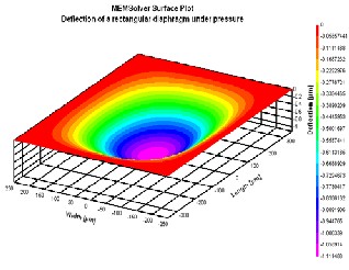
Fig 5: Simulation of a Rectangular diaphragm
rectangle thin plate and
w max (x, y) = center
under pressure
IJSER © 2013 http://www.ijser.org
International Journal of Scientific & Engineering Research, Volume 4, Issue 12, December-2013 1859
ISSN 2229-5518
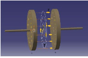
3 CAPACITOR
A capacitor is a passive two-terminal electrical component which is used to store energy electrostatically in an electric field. It contains at least two electrical conductors separated by a dielectric medium or a non-conductive region. Examples of dielectric media are glass, air, paper, vacuum, and even a semiconductor depletion region chemically identical to the conductors. The simplest capacitor consists of two parallel conductive plates separated by a dielectric with permitivity ε. The plates are considered to extend uniformly over an area A and a charge density ±ρ =
±Q/A exists on their surface. The following figure describes the proper functioning of a capacitor. [9][10].
represents the basic working of it.
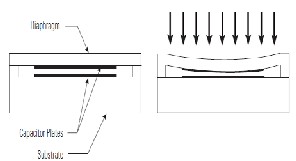
Fig 7: Change of a capacitor’s capacitance
As the pressure varies, the diaphragm expands/flexes and the distance between the capacitor plates changes. This sensor can detect even very small changes in capacitance due to small diaphragm deflections [3][10].
3.2 Blood pressure measurement using capacitive method
Now the question arises is that why should we choose this method for measuring B.P. The answer is due to its extremely small size and very less manufacturing. It’s inexpensive in case of mass production and also it has a very less risk of infection. By this method, we can continuously monitor the patient’s blood pressure allowing him to continue normal life [4].
Fig 6: Simulation of Capacitor and its field
3.1 Capacitor as a Pressure Transducer
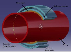
A pressure transducer is comprised of two major parts: 1) an element which is affected by pressure changes and 2) associated electronics. The pressure sensing element is a pair of parallel plates which form a capacitor. One plate is fixed to a ceramic diaphragm which moves/flexes in response to pressure changes in any situation. The other plate is atached with a rigid thing so that it is insensitive to pressure changes [3]. The following picture (8)
The basic working principle of the pressure sensor
is the change in its capacitance. It consists of a very flexible diaphragm (mostly made of silicon), two parallel plates which acts as a capacitor and a dielectric medium (b/w the plates).
The flexible diaphragm (that can easily atain a
maximum deflection under the influence of very small force acting on it) is mounted along the periphery of one of the artery. This diaphragm can expand even when there is a minute change in blood pressure. Along the diaphragm, one of the plates of the capacitor (which is also as flexible as diaphragm) is fixed. Now, there is gap maintained between the two plates of the capacitor by a dielectric medium, which is nothing but an electrical insulator. Let the average gap between the parallel plates be d, and then the expression for capacitance is given by [10]:
IJSER © 2013 http://www.ijser.org
International Journal of Scientific & Engineering Research, Volume 4, Issue 12, December-2013 1860
ISSN 2229-5518

C = ε0εr A
d
where C is the capacitance of parallel plate, 0 ε is
8.854×10⁻¹² F / m , r ε is relative permitivity of
dielectric medium, A is effective surface area, d is
the separation distance between the membrane. Now when the blood pressure in the patient’s body increases, the flow of blood through the
arteries also increases. This will lead to the
0.25
0.2
0.15
0.1
0.05
0
0.3
0.6 1.2
Dista b/w pl (µm)
1.6
nce
ates
expansion of arteries as they are also quite flexible
in nature. When the expansion of arteries takes place, this in turn leads to expansion of the diaphragm atached along its periphery. According to Pascal’s law, pressure exerted anywhere in a confined incompressible fluid is transmited equally in all directions throughout the fluid such that the pressure variations (initial differences) remain the same. So the equal force is transmited along the surface of the diaphragm. The arrangement of the setup is best explained in the
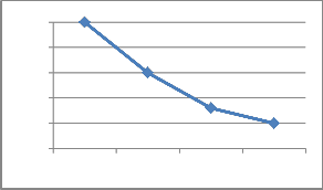
Fig 9: Graph ploted between relation of distance
and capacitance change
figure 9 given below.
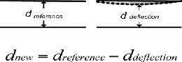
dnew
= dreference − ddeflection
IJSEFig 10: CRapacitor’s Deflection
In this, the reference is calculated without applying
any pressure onto the capacitor. Deflection distance is the one when pressure is applied onto one of the plates [2][9].
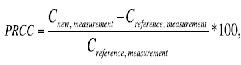
The difference between capacitance value under pressure applied and the references capacitance value results to a percentage relative change in capacitance (PRCC) is given as [2]:
Fig 8: Basic structure of a model with different
parts simulated on CATIA
The movable plate of the capacitor flexes/expands
along with the diaphragm as it is fixed to it. This
leads to the change in capacitance as the distance
between the plate’s changes.
The comparison of reference capacitance value according to distance b/w the plate is shown as given in the following figure (10).
The percentage of relative change of the capacitance value for various air gap thicknesses is ploted under pressure applied ranging from 0 mmHg to 800 mmHg.
The pressure according to no deflection or
reference deflection is known and calibrated. So the pressure for different air gaps can be easily determined at different PRCC as it varies linearly. Air gap thickness of 0.3 µm gave the highest PRCC followed by 0.7 µm and 1.2 µm while air gap thickness of 1.6 µm gives the lowest PRCC. So it can be concluded that as we increase the thickness of the VLCPS air gap, the PRCC will be decreased.
IJSER © 2013 http://www.ijser.org
International Journal of Scientific & Engineering Research, Volume 4, Issue 12, December-2013 1861
ISSN 2229-5518
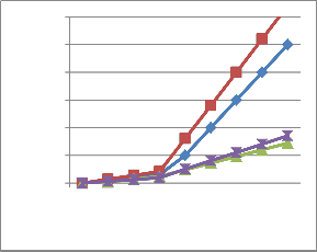
The following PRCC V/s PRESSURE APPLIED graph shows the change in capacitance at different pressures. Multiple reference distances between the plates has also been considered and accordingly we got different paths for them (as stated by lines with different colors in figure 12) [2].
30
25
20
15
10
5
0
20 40 60 80 100 200 400 600 800
Pressure applied (mmhg)
Sains Malaysiana 40(3)(2011): 259–266
[3] Mitch Berkson, Original, Dave Field, Update,
2007.Understanding and specifying sensata technologies’
capacitive pressure transducers. Pressure transducers.
[4] Flexible wireless pressure sensor module, Sensors and actuators A123-124 (2005) 30-35 Kyu-ho Shi, Chang Ryoul Moon, Tae-hee lee, Yong-Jun kim
[5] Buyong, M.R., Aziz, N.A. & Majlis, B.Y. 2008. Fabrication of thin layer membrane using CMOS process for very low pressure sensor application. Proc. IEEE International Conferences on Semiconductor Electronics, pp. 320-326.
[6] F. He, Q. –A. Huang and M. Qin, “A silicon directly bonded capacitive absolute pressure sensor,” Sensors and Actuators A 135, pp. 507–514, 2007.
[7] J. Han and et.al, “Smooth Contact Mode Capacitive Pressure Sensor with Polyimide Diaphragm,” Proceeding of IEEE conference on Sensors, Atlanta, 28-31, pp. 1468-1471, Oct. 2007.
[8] G. Meng and W. H. Ko, “Modelling of circular
IJSEdiaphragm and sRpreadsheet solution programming for touch
Fig 11: Graph between Pressure applied and
capacitance change.
4 CONCLUSION
Physical therapists and physical therapist assistants are trained in the techniques of blood pressure measurement as part of basic professional education. However, they cannot really claim to be adequately using this skill in the best interests of patients in our normal clinical practices unless it is properly and appropriately performed. But by using this technique a person can himself test or know about his blood pressure measurements and can take required action. So, in this paper a technique for blood pressure measurement based on blood flow through an artery has been discussed. The device for measuring high pressure using capacitor and diaphragm as a sensing element has been discussed.
5 REFERENCES
[1] Pradeep Kumar Rathore and Brishbhan Singh Panwar. Cmos mems based current mirror mosfet embedded pressure sensor for healthcare and biomedical applications
[2] Muhamad Ramdzan Buyong*, Norazreen Abd Aziz & Burhanuddin Yeop Majlis. MEMS Very Low Capacitive Pressure Sensor Based on CMOS Process.
mode capacitive sensors,” Sensors and Actuators A vol.75, pp. 45–52, 1999.
[9] F. He, Q. –A. Huang, and M. Qin, “A silicon directly bonded capacitive absolute pressure sensor,” Sensors and Actuators A vol. 135, pp.
507–514, 2007.
[10] Design Analysis of MEMS Capacitive Differential
Pressure for aircraft altimeter P.Eswaran and S . Malarvizhi
[11] http://www-groups.dcs.st-
and.ac.uk/~history/Mathematicians/Lagrange.html
[12] Physical and flow measurement by David Elad and
Shmuel Einav Tel Aviv University, Tel Aviv, Israel

AUTHOR’S BIOGRAPHY
Shivam Kohli is currently pursuing bachelor’s degree program in Mechatronics engineering at Manipal Institute of Technology, Manipal, INDIA.
IJSER © 2013 http://www.ijser.org
International Journal of Scientific & Engineering Research, Volume 4, Issue 12, December-2013 1862
ISSN 2229-5518
His current research interests include biomedical sensors, robotics, automation, engines, Hydraulics
and Automation, and autotronics.
Email id – shivamkohli509@ymail.com

Anish Saini is currently pursuing bachelor’s
degree program in Mechatronics engineering at Manipal Institute of Technology, Manipal, INDIA. His current research interests include biomedical sensors, robotics, PLCs, automation, engines, mechanical design, and autotronics.

Email id – anish.saini20@gmail.com
Ajesh J. Pillai is currently pursuing bachelor’s degree program in Mechatronics engineering at Manipal Institute of Technology, Manipal, INDIA. His current research interest includes automation, autotronics and manufacturing techniques.
Email id – ajeshmit@gmail.com
IJSER © 2013 http://www.ijser.org