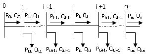
Figure 1: Single line diagram of main feeder
and, i = 1, 2, ..., n are the indices of the buses selected for
compensation.
International Journal of Scientific & Engineering Research, Volume 5, Issue 6, June-2014 76
ISSN 2229-5518
Loss Reduction with Optimization of DG Placement Using Genetic Algorithm and
Comparison with PSO Method - A Case Study in IRAN
Moein Khosravi1*, Dr. Mahdi Mozaffari Legha2, Gholamreza Mirzaei3
Abstract
Increasing application of DG units on distribution networks is the direct impact of development of technology and the energy disasters that the world is encountering. To obtain these goals the resources capacity and the installation place are of a crucial importance. Line loss reduction is one of the major benefits of DG, amongst many others, when incorporated in the power distribution system. The quantum of the line loss reduction should be exactly known to assess the effectiveness of the distributed generation. In this paper, a new method is proposed to find the optimal and simultaneous place and capacity of these resources to reduce losses, improve voltage profile too the total loss of a practical distribution system is calculated with and without DG placement and an index, quantifying the total line loss reduction is proposed. To demonstrate the validity of the proposed algorithm, computer simulations are carried out on actual power network of Kerman Province, Iran and the simulation results are presented and discussed.
Keywords: Distribution systems, Loss reduction index, DG placement, Artificial Bee Colony, PSO method
—————————— ——————————
he loss minimization in distribution systems has assumed greater significance recently since the trend towards distribution automation will require the most efficient operating scenario for economic viability variations. The power losses in distribution systems correspond to about 70% of total losses in electric power systems (2005). To reduce these losses, shunt DG units are installed on distribution primary feeders. The advantages with the addition of shunt DGs units are to improve the power factor, feeder voltage profile, Power loss reduction and increases available capacity of feeders. Therefore it is important to find optimal location and sizes of DGs in the system to achieve the above mentioned objectives. Since, the optimal DG placement is a complicated combinatorial optimization problem, many different optimization techniques and algorithms have been proposed in the past. H. Ng et al (2000) proposed the DG placement problem by using fuzzy approximate reasoning. Ji Pyng Chiou et al (2006) proposed the variable scale hybrid
————————————————
South, Kerman, Iran (E-mail: Ieeereza.mirzaei@gmail.com ).
differential evolution algorithm for the DG placement in distribution system. Both Grainger et al (1981) and Baghzouz and Ertem (1990) proposed the concept that the size of DG units was considered as a continuous variable. However, considered only the losses in the lines and the quantification were defined for the line losses only. These indices, therefore, do not indicate the loss reduction of the system itself. A practical distribution system consists of several distribution transformers, supplying consumers at low voltage on the secondary side. The losses occurring in these transformers and the line losses of the secondary low voltage distribution system should also be considered to arrive at the overall loss reduction of the system.
In this paper, a new method is proposed to find the
optimal and simultaneous place and capacity of these
resources to reduce losses, improve voltage profile too the total loss of a practical distribution system is calculated with and without DG placement and an index, quantifying the total line loss reduction is proposed. To demonstrate the validity of the proposed algorithm, computer simulations are carried out on actual power network of Kerman Province, Iran and the simulation results are presented and discussed.
The objective of DG placement in the distribution system is to minimize the annual cost of the system, subjected to certain operating constraints and load pattern. For simplicity, the operation and maintenance cost of the DG
IJSER © 2014 http://www.ijser.org
International Journal of Scientific & Engineering Research, Volume 5, Issue 6, June-2014 77
ISSN 2229-5518
placed in the distribution system is not taken into
𝐶𝑂𝑆𝑇 = 𝐾𝑝 × 𝑃𝑇
𝑐
𝑐𝑓
𝑖 𝑖
consideration. The three-phase system is considered as
balanced and loads are assumed as time invariant.
𝐿𝑂𝑆𝑆 + � �𝐾
𝑖
+ 𝐾𝑐 𝑄𝑐 �
Mathematically, the objective function of the problem is described as:
Where n is number of candidate locations for DG
placement, Kp is the equivalent annual cost per unit of
power loss in $/(Kw-year); KRcfR is the fixed cost for the DG
𝑐
𝑀𝑖𝑛𝑖𝑚𝑖𝑧𝑒 𝑓 = 𝑀𝑖𝑛 (𝐶𝑂𝑆𝑇)
placement. Constant 𝐾𝑖
is the annual DG installation cost,
Where COST includes the cost of power loss and the DG placement, the voltage magnitude at each bus must be maintained within its limits and is expressed as:
𝑉𝑚𝑖𝑛 ≤ |𝑉𝑖 | ≤ 𝑉𝑚𝑎𝑥
Where │Vi│ is the voltage magnitude of bus i, VRminR and
VRmaxR are bus minimum and maximum voltage limits, respectively.
The power flows are computed by the following set of simplified recursive equations derived from the single- line diagram depicted in Figure. 1.
Figure 1: Single line diagram of main feeder
and, i = 1, 2, ..., n are the indices of the buses selected for
compensation.
The Backward Sweep calculates the current injected into each branch as a function of the end node voltages. It performs a current summation while updating voltages. Bus voltages at the end nodes are initialized for the first iteration. Starting at the end buses, each branch is traversed toward the source bus updating the voltage and calculating the current injected into each bus. These calculated currents are stored and used in the subsequent Forward Sweep calculations. The calculated source voltage is used for mismatch calculation as the termination criteria by comparing it to the specified source voltage. The Forward Sweep calculates node voltages as a function of the currents injected into each bus. The Forward Sweep is a voltage drop calculation with the constraint that the source voltage used is the specified nominal voltage at the beginning of each forward sweep. The voltage is calculated at each bus, beginning at the source bus and traversing out to the end buses using the currents calculated in previous the
Backward Sweep [5]. The flow chart of proposed Power
2 2
𝑃𝑖+1 = 𝑃𝑖 − 𝑃𝐿𝑖+1 − 𝑅𝑖𝑗 +1![]()
𝑃𝑖 + 𝑄𝑖
|𝑉𝑖 |2
Flow Analysis method is depicted in Figure 2.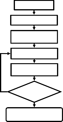
2 + 𝑄2
𝑄𝑖+1 = 𝑄𝑖 − 𝑄𝐿𝑖+1 − 𝑋𝑖𝑗+1
|𝑉𝑖 |2![]()
Input Data
Where Pi and Qi are the real and reactive powers flowing out of bus i, and PRLiR and QRLiR are the real and reactive load powers at bus i. The resistance and reactance of the line section between buses i and i+1 are denoted by RRi,i+1R and XRi,i+1R respectively. The power loss of the line section connecting buses i and i+1 may be computed as
The model coefficients are computed once
Backward forward Sweep
load flow computation
Calculation of real and
2 2 reactive power
𝑃𝐿𝑜𝑠𝑠 (𝑖, 𝑖 + 1) = 𝑅𝑖,𝑖+1![]()
𝑃𝑖 + 𝑄𝑖
|𝑉𝑖 |2
Calculate the branch
The total power loss of the feeder, 𝑃𝐿𝑂𝑆𝑆
may then be
current of the bus and the
determined by summing up the losses of all line sections
of the feeder, which is given as
𝑛−1
𝐿𝑂𝑆𝑆
𝑇
= � 𝑃𝐿𝑂𝑆𝑆 (𝑖, 𝑖 + 1)
𝑖=0
No Accuracy < ΔV
Therefore, for each installation location, there are L DG
sizes {1SRDGR, 2 SRDGR, 3 SRDGR, …, L SRDGR } available. Given the annual installation cost for each compensated bus, the total cost due to DG placement and power loss change is written as
Yes
Calculate the branch current of the bus and the first bus
IJSER © 2014 http://www.ijser.org
International Journal of Scientific & Engineering Research, Volume 5, Issue 6, June-2014 78
ISSN 2229-5518
Figure 2: Flowchart of the Backward-Forward sweep method
GA’s are generalized search algorithms based on the mechanics of natural genetics [14]. GA maintains a population of individuals that represent the candidate solutions to the given problem. Each individual in the population is evaluated to give some measure to its fitness to the problem from the objective function. GA’s combine solution evaluation with stochastic operators namely, selection, crossover and mutation to obtain optimality. [12].
The total loss of the distribution system without DG is
given by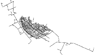
total connected load on the system is 2550 KVA and the peak demand for the year is 2120 KVA at a PF of 0.8 lag.
Figure 3: Single-line diagram of actual power network of
Kar feeder of Kerman Province
Table 1: Details of transformers in the system
𝑁−1
𝑁−1
2 × 𝑟 × 𝐿 + ��𝑃
+ 𝑃 �
𝐿𝑜𝑠𝑠 𝑤𝑖𝑡ℎ𝑜𝑢𝑡 𝐷𝐺 = � 𝐼𝑖
𝑖 =1
𝑖
𝑖 =1
𝑐𝑖
𝐿𝑣 𝑖
Where IRiR is the current flowing through ith section, r is
the resistance of line in ohms per unit length, LRiR is the
length of ith section, PRciR is the core loss of ith transformer,
PLvi is the Losses on the low voltage side of the ith
transformer and N is the number of busses in the system.
In order to determine the losses of the system, the core
loss of each transformer and the LV side losses on each transformer must be known. It is evident from the above equation that the total losses can be reduced only by reducing the first term which represents the feeder line losses, since the other term representing the core loss and the LV side loss of each transformer remain same independent of the presence of DG. If a DG is inserted at Kth bus, the feeder segments up to bus K will carry the difference of the initial current and the injected current by the DG. Where IRCapR is the current injected by the DG and IRiR remains the same at earlier value. The total loss of the distribution system with DG is now
𝐿𝑜𝑠𝑠𝑤𝑖𝑡ℎ 𝐷𝐺 = ∑𝐾−1�𝐼𝑖 − 𝐼𝐶𝑎𝑝 � 𝑟𝐿𝑖 +
Table 2: Details of conductors in the system
Type | R [Ω/km] | X [Ω/km] | Cmax [A] | A [mm2] |
Hyena | 0.1576 | 0.2277 | 550 | 126 |
Dog | 0.2712 | 0.2464 | 440 | 120 |
Mink | 0.4545 | 0.2664 | 315 | 70 |
Initially, a load flow was run for the case study in both fundamental frequency and harmonics frequencies without installation of DG. Table 3 depicts the locations and capacity of DG units using Genetic Algorithm. Table
4 and 5 depicts the results of power flow for
determination voltage before and after installation of DG.
As it is clear, all the obtained values confines with all the considered constraints. The obtained penetration lever is
0.27, which is less than the assumed allowable value. In
𝑁−1 2
𝑁−1
addition the total network loss, which was 10.05MW
∑𝑖=𝑘 𝐼𝑖 𝑟𝐿𝑖 + ∑𝑖=1 �𝑃𝑐𝑖 + 𝑃𝐿𝑣 𝑖 �
To study the proposed method, actual power network of Kar feeder of Kerman Province, Iran is simulated in Cymedist. Figure 3 illustrates the single-line diagram of this network. The base values of the system are taken as
20kV and 20MVA. The system consists of 20 distribution
transformers with various ratings. The details of the distribution transformers are given in table 1. The details of the distribution conductors are given in table 2. The
before installing DG, has diminished to the 4.55MW which shows 45.81% decrease. Table 5 shows the impact of installing DG on THD of buses.
Table 3: Optimal place and capacity of DG units
IJSER © 2014 http://www.ijser.org
International Journal of Scientific & Engineering Research, Volume 5, Issue 6, June-2014 79
ISSN 2229-5518
Table 4: Results of power flow before installation of DG
Bus Number | V (pu) |
1 | 1.0 |
2 | 0.9999 |
3 | 0.9998 |
4 | 0.9988 |
5 | 0.9988 |
6 | 0.9987 |
7 | 0.9985 |
8 | 0.9889 |
9 | 0.9879 |
10 | 0.9849 |
11 | 0.97 |
12 | 0.93 |
13 | 0.89 |
14 | 0.9849 |
15 | 0.9849 |
16 | 0.91 |
17 | 0.92 |
18 | 0.95 |
19 | 0.94 |
20 | 0.89 |
Table 5: Results of power flow after installation of DG
units
These results reveal that the inclusions of DG reduce the line losses as expected. It can be shown from the graphs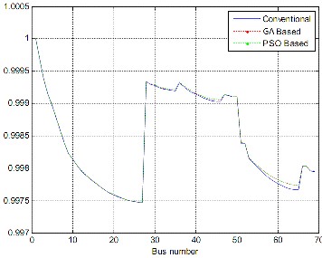
Figure 4: Voltage profiles of 69-bus system
that, LRI decreases marginally, since the core losses of the transformers and the LV side losses remain constant being independent of the presence of Table 6. It can also be seen that with the increase in the reactive power of DG, LRI, decrease.
Table 6: Obtained Loss results
The detailed pu voltages profile of all the nodes of the system before and after DG placement are shown in the Figure 4. The simulation results are given in Table 6.
In the present paper, a new population based Genetic Algorithm (GA) has been proposed to solve DG placement
Problem and quantifying the total line loss reduction in distribution system. Simulations are carried on actual power network of Kerman Province, Iran. The simulation results show that the inclusion of DG, marginally reduce the losses in a distribution system. This is because; the line losses form only a minor part of the distribution system losses and the DG can reduce only the line losses. The other losses viz. the transformer losses and the LV side distribution losses remain unaltered. Hence this fact should be considered before installing a DG into a system. The results obtained by the proposed method
IJSER © 2014 http://www.ijser.org
International Journal of Scientific & Engineering Research, Volume 5, Issue 6, June-2014 80
ISSN 2229-5518
outperform the other methods in terms of quality of the solution and computation efficiency.
[1] Mahdi Mozaffari Legha, "Determination of exhaustion and junction of in distribution network and its loss maximum, due to geographical condition", MS.c Thesis; Islamic Azad University, Saveh Branch, Markazi Province, Iran; pp. 1-300, Aug 2011.
[2] Mahdi Mozaffari Legha, Rouhollah Abdollahzadeh, Ardalan Zargar, Mostafa Shadfar. “Effective method for optimal allocation of distributed generation units in radial electric power systems by genetic algorithm and imperialist competitive algorithm”, International Journal on Technical and Physical Problems of Engineering (IJTPE), Issue 15, Vol. 5, No. 2, pp. 70-74, June 2013.
[3] Mahdi Mozaffari Legha, Moein khosravi, Mohammad Hossein Armand, Mahdiyeh Azh,, “Optimization of Location and Capacity DGs Using HPSO Approach Case Study on the Electrical Distribution Network of north Kerman Province”, Middle-East Journal of Scientific Research, pp. 461-465, 2013.
[4] Mahdi Mozaffari Legha,; ”Optimal Conductor Selection of Radial Distribution Networks Using GA Method” CIRED Regional – Iran, Tehran, 13-14 Jan 2013; Paper No: 12-F-500-0320.
[5] Mahdi Mozaffari Legha and et al, ’’A new hybrid particle swarm optimization approach for sizing and placement enhancement of distributed generation’’ IEEE Conference, 2155-5516; Pages 1277 -
1281.
[6] Web site Electrical Power Engineering Specialists, REPORTs,
2014. Available at: <http://www.drmozaffarilegha.com.com> [accessed 01.01.2014]
[7] Mahdi Mozaffari Legha, Houman Gadari1,, “Technical and Economical Evaluation of Solar Plant for Electricity Supply Anar City Residential Customers”, Middle-East Journal of Scientific Research, pp. 455-460, 2013.
[8] Mahdi Mozaffari Legha, Farzaneh Ostovar, “Analysis and Reconductoring of Overhead Conductors with Considering aging for Radial Distribution Systems Using Imperialist competitive Algorithm”, International Journal of Pure and Applied Sciences and Technology, Vol. 20, No. 1, January 2014, pp. 1-8.
[9] Ji-Pyng Chiou et al (2006), “DG placement in large scale distribution system using variable scaling hybrid differential evolution”, Electric Power and Energy Systems, vol. 28, pp.739-745. [10] J. L. Bala, P. A. Kuntz, M. Tayor (1995), “Sensitivity-based optimal DG placement on a radial distribution feeder”, Proc. Northcon 95, IEEE Technical Application Conf., pp. 225230.
[11] D. Karaboga, B. Basturk(2008), “On the performance of Genetic
Algorithm (GA)”, Applied Soft Computing, vol. 8 pp. 687-697.
[12] Prakash K. and Sydulu M (2007), “Particle swarm optimization based DG placement on radial distribution systems”, IEEE Power Engineering Society general meeting 2007, pp. 1-5.
[13] D. Das (2002), “Reactive power compensation for radial distribution networks using Genetic algorithms”, Electric Power and Energy Systems, vol. 24, pp.573-581.
[14] D. Karaboga, B. Basturk(2008), “On the performance of Genetic
Algorithm (GA)”, Applied Soft Computing, vol. 8 pp. 687-697.
[15] Chiradeja, Ramkumar , “ An Approach to quantify the Benefits of Distrributed Generation Systems”, IEEE trans. On Energy Conversion, Vol. 19, Dec 2004, pp 764 – 773.
[16] B. Basturk, D. Karaboga (2006), “An Genetic Algorithm (GA) for numeric function optimization”, IEEE Swarm Intelligence Symposium 2006, May 12-14, Indianapolis, IN, USA.
[17] N. Medina, M.M. Qi, L. Butler-Purry, K.L. A Three Phase Load
Flow Algorithm for Shipboard Power Systems (Sps), 2003.
[18] T. Gönen, Electric Power Distribution Systems Engineering. New York: McGraw-Hill, 1986.
[19] E. Atashpaz-Gargari, C.Lucas, ’’Imperialist competitive algorithm: an algorithm for optimization inspired by imperialistic competition’’. IEEE Congre vol11 Comput 2007:4661–7.
[20] Mahdi Mozaffari Legha and et al, ’’A new hybrid particle swarm optimization approach for sizing and placement enhancement of distributed generation’’ IEEE Conference, 2155-
5516; Pages 1277 - 1281.
[21] Mahdi Mozaffari Legha,;”Optimal Conductor Selection of Radial Distribution Networks Using GA Method” CIRED Regional – Iran, Tehran, 13-14 Jan 2013; Paper No: 12-F-500-0320.
[22] M. Vahid, N. Manouchehr, S. D. Hossein, and A. Jamaleddin,
“Combination of optimal conductor selection and capacitor placement in radial distribution systems for maximum loss reduction“ in Proc. 2009 IEEE Int. Conf. Industrial Technology, Gippsland, Australia, Feb. 10–13, 2009, pp. 01–05
[23] Mahdi Mozaffari Legha, Marjan Tavakoli, Farzaneh Ostovar,
Milad Askarihashemabadi, “Capacitor Placement in Radial Distribution System for improve network efficiency Using Artificial Bee Colony“, International Journal of Engineering Research and Application, Vol. 3, Issue 6, Nov-Dec 2013, pp.01-05
[24] Mahdi Mozaffari Legha, Rouhollah Abdollahzadeh, Ardalan Zargar, Mohammad Mozaffari Legha,, “Cocnductor Size Selection in Planning of Radial Distribution System for Productivity Improvement Using Imperialist Compotitive Algorithm”, International Journal on Technical and Physical Problems of Engineering (IJTPE), Issue 15, Vol. 5, No. 2, June 2013, pp. 65-69.
[25] Ng H.N., Salama M.M.A. and Chikhani A.Y (2000), “DG allocation by approximate reasoning: fuzzy DG placement”, IEEE Transactions on Power Delivery, vol. 15, No. 1, pp. 393-398.


stability of power systems and electrical distribution systems. He has published more than 25 journal papers and presented more than 60 international conference papers.

stability of power systems and power quality in distribution systems.