International Journal of Scientific & Engineering Research, Volume 3, Issue 11, November-2012, ISSN 2229-5518
Large Scale Mapping Using Digital Aerial
Imagery of Unmanned Aerial Vehicle
Wani Sofia Udin and Anuar Ahmad
Abstract- The advancement in digital photogrammetry has made photogrammetric technique become simpler, faster and lower cost. Currently, this method is quite popular in covering small and large area. This study examines the use of digital camera of high resolution in capturing aerial photograph based on unmanned aerial vehicle (UAV) as the airborne platform. The study area covered is the area of Universiti Teknologi Malaysia main campus and its surrounding area. Canon Pentax W90 is utilized as non-metric camera for the earth information acquisition. Secondary data of ground control points and check points established using rapid static technique of GPS were used. All the aerial photographs were processed using digital photogrammetric software and the output in the form of contour line and orthophoto were produced. The research output is then evaluated for planimetry and vertical accuracy using root mean square error (RMSE). Based on the analysis, sub-meter accuracy is obtained. As conclusion, UAV system has potential use for large scale mapping or other diversified applications especially for small area which has limited time and less man power. The map or the orthophoto produced from this system can be used as base map in Geographical Information System (GIS) and various fields such as geomatic, engineering, construction industry, planning etc.
Keywords- The research paper published by IJSER journal is about Large scale mapping using digital aerial imagery of unmanned aerial vehicle
1 INTRODUCTION
HOTOGRAMMETRY means a three dimensional coordinate measuring technique which utilizes photographs as the fundamental medium for measurement. Early development in the theory and science of photogrammetry occurred many years before the actual invention of a suitable means to apply the application. Over the years, photogrammetry has gone through several development phases and now entered into digital photogrammetry phase. Aerial photogrammetry involves the acquisition of aerial photograph using metric camera from aircraft, helicopter, hot air balloon, kite or parachurte. More recent, aerial photograph could be acquired using metric digital aerial camera, however, not many mapping organizations afford to use the latest technology in acquiring digital images of aerial photograph. The compatibility of small format digital camera introduces new era for photogrammetrist. Normally the accuracy of small format digital camera is relatively lower than using metric camera. However, the use of digital camera is still acceptable and preferable since digital images could be obtained directly, digital images could stored on-board, easy to operate and not necessary to use direct current [2]. Apart from that, the cost for implementing a project is much cheaper if compared to the conventional method. Also the small format digital camera can be attached to a very light platform such as the
unmanned aerial vehicle (UAV).
————————————————
Wani Sofia Udin is currently pursuing doctor of philosophy program in geomatic engineering in Universiti Teknologi Malaysia, Johor, Malaysia, PH-0129495542. E-mail: wanisofia@umk.edu.my
Anuar Ahmad is lecturer and associate professor in department of geoinformatics in University Teknologi Malaysia, Johor, Malaysia, PH-
0197633125. E-mail: anuarahmad@utm.my
Digital photogrammetric method involves processing the digital images of aerial photograph using computer. The digital images can be captured directly using digital camera or scanned from aerial photographs. As the product are in digital form, they can be easily stored and manage such as digital map, DEM and digital orthophoto can be saved in computer storage media.
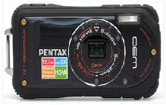
In this study, the small format aerial photographs were acquired using compact digital camera and UAV system. The Pentax Optio W90 high resolution digital camera is attached to an UAV as data acquisition system in acquiring aerial photograph of the study area.
UNMANNED AERIAL VEHICLE (UAV) AND DIGITAL CAMERA
UAV is an aircraft, flying in the air with no pilot onboard and with capability for remote controlling the aircraft as describe by [8]. UAV was developed by military during World War I and II for reconnaissance and surveillance purpose [5]. Today, the civilian is able to operate the UAV for photogrammetry application. Equipped with GPS, INS, autopilot system and others, the system is designed to collect data for mapping and image interpretation purposes working on areas. More applications of UAV-systems in photogrammetry became common. “Laliberte et.al”[4] used images taken from two UAVs that differed in size, payload capacity, flight duration, GPS guidance capability and cost for determining the utility of UAVs for rangeland mapping. There are also larger fixed wing low-altitude aircraft are being used in agriculture and multipurpose monitoring. These systems are able to fly autonomously.
The advantages in developing the technology of UAV for low altitude photogrammetric mapping are to perform aerial photography at cloudy day, to get full image of object under study from aerial, and to supply a cheap and easy system for high frequency needs of aerial photogrammetric survey [6]. Cropcam UAV is considered as the type of low altitude UAV
IJSER © 2012 http://www.i jser.org
International Journal of Scientific & Engineering Research, Volume 3, Issue 11, November-2012, ISSN 2229-5518
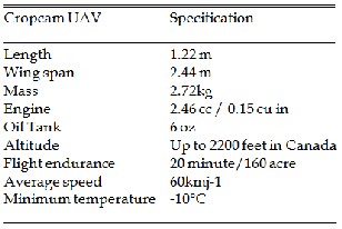
system as shown in Figure 1. The Cropcam is a radio controlled model glider plane equipped with a Trimble GPS, a miniature autopilot and Pentax digital camera. It offers images on demand and is an inexpensive alternative to satellite or flying on the airplane over a field. The specification of Cropcam UAV is shown in Table 1.
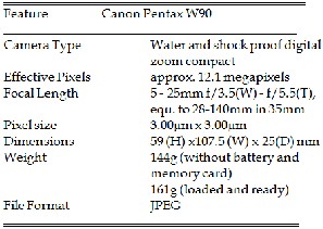
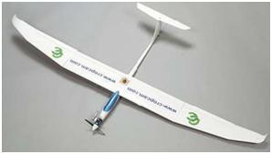
Fig 1. Cropcam UAV
TABLE 1.
CROPCAM UAV SPECIFICATION
Fig 2. Canon Pentax W90 digital camera
2 RESEARCH METHODOLOGY
The research methodology adopted in this study is shown in Figure 3. Each phase of the study is explained as the procedure of large scale mapping using digital aerial imagery.
Digital camera is categorized as non-metric camera where the camera is not specifically built for photogrammetric purposes. Digital camera is not characterized with fiducial mark, unstable calibration parameter, small format and many more [9]. Figure 2 shows the Canon PENTAX W90 digital camera with interactive 12.1 Megapixel together with the camera specification. Canon Pentax W90 digital camera has
5x optical zoom lens and 2.7” liquid crystal display (LCD)
screen. It is offers a high resolution, with a maximum 4000 x
3000 pixels. Canon Pentax camera was attached at the bottom
of Cropcam UAV to capture aerial images during flight operation.
2.1 Preparation Stage
This stage investigates the purpose of the study. Due to focus under study, the photographic scale, flying height of UAV, coverage and others were determined. Therefore, few aspects involved in preparation such as flight planning and properly install the instrument were considered. The area must be easily accessible. The area should include open area for easy takeoff and landing of the platform or UAV. It also involved the determination of 60% side lap and 30% end lap. A well- organized image requires an essential arrangement because it is vital for data processing and analysis. Before any observation start, first step that need to be done is to properly install the instruments. There are few important components of the system in autonomous fly as shown in Figure 4.
IJSER © 2012 http://www.i jser.org
International Journal of Scientific & Engineering Research, Volume 3, Issue 11, November-2012, ISSN 2229-5518
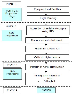
Fig. 3. Flow chart of research methodology
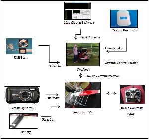
Fig. 4. Instrument Installation Diagram
2.2 Data Acquisition
The study area was at Universiti Teknologi Malaysia (UTM) main campus in Johor Bahru, Malaysia and it is shown by the red oval on the aerial photograph acquired using Wild RC30 aerial camera (Figure 6). Flying height and speed were fixed, with an average flying height of 320 m. A timing interval was determined in order to obtain consistent flying axes with 60%
overlapping. The Cropcam UAV is manually take-off at the proposed area as well as landing process. Figure 5 represents how the Cropcam UAV and Ground Control Station were carried out. Several strips of the image in JPEG (Joint Photographic Experts Group) are captured then transfer to the notebook for image processing. On-site calibration is also done for the aerial imagery. Figure 6 shows the study area and a strip of overlapping aerial photograph captured using the Pentax Optio W90 digital camera of 12.1 megapixel resolutions.
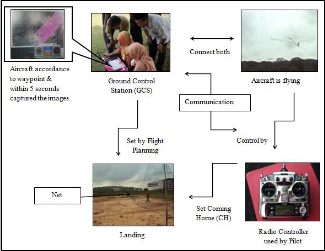


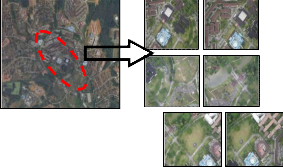
Fig. 5. Cropcam UAV and Ground Control Station
Fig. 6. Study Area (left) and example for one strip of aerial photograph
(right)
2.3 Establishment of GCP and CP
The GCP and CP were established after the aerial photography mission and formation of uncontrolled mosaic is carried out. The GCPs were collected using GPS observation through Rapid Static technique. This technique can provide the position information includes Northing, Easting, and Elevation (X, Y, and Z) with the post processing by using the Trimble Total Control (TTC) software and provides accuracy at the 0 to 10 centimeter level. Any point is on the earth has been identified on aerial photographs like corner of the road, building, drain and etc. consider as GCPs were measured to get the coordinate which enclosed the overlapped area as shown in Figure 7.
IJSER © 2012 http://www.i jser.org
International Journal of Scientific & Engineering Research, Volume 3, Issue 11, November-2012, ISSN 2229-5518
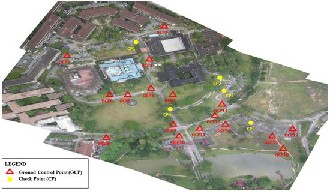
Fig. 7. The location of GCP and CP
2.4 Camera Calibration
Camera calibration is carried out before image processing is done. A Pentax Optio W90 digital camera was calibrated using a 3D testfield. The calibration plate has a dimension of 0.4 meter x 0.4 meter and consists of 36 screws of different height and arranged in matrix form of 6 x 6 units. On top of each screw, retro-reflective target is stick on it. Convergent photographs were taken with eight pieces of photographs for each camera. The photographs were taken with the camera in normal landscape position and then rolled it at 90°; and the photographs were acquired from four different camera locations in space. The digital camera needs to be rotate 90° with the purpose to recover the principle point.
The acquired digital images were downloaded one by one
into a PC using appropriate software for image measurement.
Targeted points were then measured automatically using Australis software. Then Australis perform the self-calibration bundle adjustment process and generate 3D coordinates of all the retro-reflective targets. Australis also provides the value of camera calibration parameters of each digital camera. This software can produce a value of precision known as posteriori variance factor (Sigma nought). The smallest value reflects the highest precision. The digital camera was calibrated one at a time. From the calibration process, 10 parameters were re- covered. However, only 8 parameters were used.
2.5 Data Processing
Digital image processing is carried out in this phase for deriving mosaic orthophoto from UAV imagery. The Ensomosaic software is exploited to process the digital image of small format camera. The GCPs is used to perform the aerial triangulation in order to produce stereoscopic model. The step is continued by generating orthophoto of the digital aerial imagery.
2.6 Analysis
Last stage of the study comprises of analysis in qualitative and quantitative technique. The qualitative is done by analyzing the quality of orthophoto and contour line generation.
Meanwhile, the quantitative analysis is performed by using Root Mean Square Error (RMSE). The arbitrary coordinates system (X, Y, and Z) of control and check points derived using Total station were compared with estimates established by photogrammetry. The RMSE is carried out by using equation shown in Equation 1.
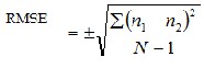 ………. (1)
Where,
n1 = differences value between two parametres n2 = mean differentiation
N = total no. of points
3 RESULTS
Based on the study, three sets of output are obtained. The first result is camera calibration parameter derived from camera calibration process and second is orthophoto of the digital aerial imagery. The last outcome is contour.
3.1 Camera Calibration Parameters
Table 2 shows the parameters of camera calibration parameters of Canon Pentax W90 digital camera. The camera calibration parameters consist of the focal length (c), principal point offset (xp, yp), radial (k1, k2, k3) and tangential (p1, p2) lens distortion, “affinity” (b1) and different in scale factor (b2).
TABLE 2.
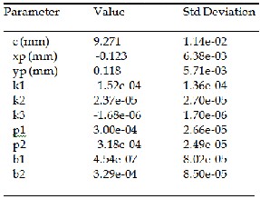
CAMERA CALIBRATION PARAMETERS
3.2 Orthopohoto
Subsequently, a series of digital aerial imagery of the small format non-metric camera was used to produce orthophoto. The orthophoto was created after the formation of aerial
IJSER © 2012 http://www.i jser.org
International Journal of Scientific & Engineering Research, Volume 3, Issue 11, November-2012, ISSN 2229-5518
triangulation of digital imagery with 60% endlap and 30% sidelap overlapping by using established GCPs. Figure 8 shows the orthophoto of UTM digital aerial imagery. The quality of the orthophoto is then validates with accurate Rapid Static GPS of check points (CP).
Fig. 9. Contour line of UTM precint
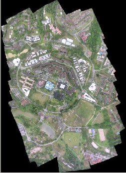
Fig. 8. Orthophoto of UTM digital aerial imagery
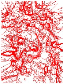
3.3 Contour
Apart from orthophoto, contour line is also generated. Figure 9 depicts the contour generated based on aerial triangulation process. Fine red color shows higher terrain elevation while thick red displays the lower terrain elevation of UTM precinct. The generated contour line is overlaid with orthophoto generated using the same digital photogrammetric software. The contour line interval generated for small format aerial photograph is 1 meter. In this study, the contour lines and the orthophoto should fit together. Figure 10 shows the contour lines overlaid with orthophoto produced in Ensomosaic for small format aerial photograph using ArcGIS.
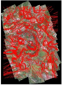
Fig. 10. Contour lines produced by Ensomosaic for small format aerial photograph are overlaid with Orthophoto in ArcGIS.
4 ANALYSIS
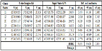
The orthophoto generated was analyzed by comparing with Rapid Static GPS coordinate. The accuracy of orthophoto planimetry and vertical is shown in Table 3. In planimetry accuracy, a sub-meter ±0.555m and ±0.624m were obtained for X and Y coordinates respectively. Meanwhile the RMSE for Z coordinates is ±1.117m. For average RMSE, ±0.766m was obtained by averaging the planimetry and vertical RMSE of small format digital imagery orthophoto.
IJSER © 2012 http://www.i jser.org
International Journal of Scientific & Engineering Research, Volume 3, Issue 11, November-2012, ISSN 2229-5518
TABLE 3.
RMSE OF DIGITAL AERIAL IMAGERY ORTHOPHOTO AND RAPID STATIC GPS
5 CONCLUSION
Based on this study, the digital aerial imagery of Cropcam UAV can be used for large scale mapping. The sub-meter accuracy produced by the data is relevant for various applications with low cost expenditure and less expert manpower. Besides, the flexibility and high efficiency of the UAV flight would be a solution for real-time mapping. It is because UAV can take-off and landing at limited open area with autopilot controlling. The map or the orthophoto produced from this system can be used in various fields such as Geographical Information System (GIS), geomatic, engineering, construction industry, planning etc. This study is more extensive if compared to the previous work done by [9]. The previous work used only two strips of digital photographs acquired using low cost digital camera mounted on fixed wing Cropcam UAV and then processed using Erdas Imagine software. The study is performs to assess the accuracy of DTM derived from UAV platform. The research output is then evaluated for planimetry and vertical accuracy using RMSE.
ACKNOWLEDGMENT
The authors would like to acknowledge the support of Faculty of Geoinformation & Real Estate, Universiti Teknologi
Malaysia in conducting this study. The authors also would like to express their great thanks to Universiti Malaysia Kelantan (UMK) for supporting this study. Further, authors would like to thanks the Research Management Center (RMC) of Universiti Teknologi Malaysia and Ministry of Higher Education Malaysia for guidance and supporting this study.
BIBLIOGRAPHY
[1] A.Ahmad, “Digital Mapping Using Low Altitude UAV,”Pertanika Journal of
Science and Technology. Vol. 19 (S): pg 51 – 58 Oct, 2011.
[2] A.Ahmad, “Mapping Using Small Format Digital Imagery and Unmanned Aerial Platform,”In South East Asia & Survey Congress, 4-6 August; Bali, Indonesia, 2009.
[3] A.Ahmad, K.A. Hashim, A.M. Samad, “Aerial Mapping using High Resolution Digital Camera and Unmanned Aerial Vehicle for Geographical Information System,”2010 6th International Colloquium on Signal Processing & Its Applications (CSPA). Pg 201 – 206, 2010.
[4] A.Laliberte, A.Rango and J.E. Herrick, “Unmanned AerialVehicles for Rangeland Mapping and Monitoring: A Comparison of Two Systems,” American Society for Photogrammetry and Remote Sensing Proceedings, May 7-11, 2007, Tampa, Florida. 2007.
[5] H.Eisenbeiss, “A Mini Unmanned Aerial Vehicle (UAV): System Overview and Image Acquisition,”International Workshop on Processing and Visualization Using High-Resolution Imagery. Nov 2004. Pitsanulok, Thailand, 2004.
[6] L.Z. Jian, “UAV for Mapping – Low Altitude Photogrammetric Survey,”The
International Archives of the Photogrammetry, Remote Sensing and Spatial
Information Sciences. Part B1. XXXVII, 1183-1186, 2008.
[7] R.B. Haarbrink and H.Eisenbeiss, “Accurate DSM Production from Unmanned Helicopter Systems,”The International Achieves of the Photogrammetry, Remote Sensing and Spatial Information Sciences. Vol. XXXVII, Part B1, Beijing, 2008.
[8] U.Coppa, A.Guarnieri, F.Pirotti and A.Vettore, “Accuracy Enhancement of Unmanned Helicopter Poisitioning with Low Cost System,”ISPRS (International Society of Photogrammetry and Remote Sensing. Vol. XXI Congress, Beijing, China, 2008.
[9] W.S. Udin, A.F. Hassan, A.Ahmad and K.N. Tahar, “Digital Terrain Model
Extraction Using Digital Aerial Imagery Of Unmanned Aerial Vehicle,” 2012
IEEE 8th International Colloquium on Signal Processing and Its Applications
(CSPA),Malacca,Malaysia2012.
IJSER © 2012 http://www.i jser.org