International Journal of Scientific & Engineering Research, Volume 4, Issue 4, April-2013 1189
ISSN 2229-5518
Kinetic Energy Regeneration System for Fuel
Efficiency and Performance Enhancement
Sidharth Dave, Aneesh Bhardwaj
*Both the authors have contributed equally to this paper
Abstract— Advancements in technology and ever increasing demands of the society are putting huge pressure on the existing fuel resources and are a constant threat to its sustainability. To bring out the best in automobile, optimum balance between performance and fuel efficiency is essential. In the present scenario, either of the above two factors are taken into consideration during the design and development process which jeopardises the other as increment in fuel efficiency leads to decrement in performance and vice -versa. In- depth analysis of the vehicle dynamics clearly shows that lar ge amount of energy is lost during braking and large quantity of fuel is consumed to regain the initial state, leading to lower fuel efficiency to gain same performance. Current Kinetic Energy Regeneration Systems are used for motorsports and are temporary in nature as power can be extracted during a small time interval only and use of superior parts leads to high cost, concentrating on performance only. In this paper Kinetic Energy Regeneration system for ha rnessing the power and then using the same while accelerating has been discussed. The major energy storing element in this system is a spring that will store energy by compression and torsion.
The use of spring ensures permanent storage of energy until called upon by the driver unlike current mechanical regeneration systems in which the energy stored reduces with time and is eventually lost. Continuously variable transmission will be used in order to make the energy release uniform which will lead to safe usage. The system can be used to improve fuel ef ficiency by assisting in overcoming the vehicle’s inertia after braking or to provide instant acceleration whenever required by the driver. This system allows the en ergy to be released either in a single pass or in varied intervals, complementing the versatility of the system. The performance characteristics of the system including the response time, accuracy and overall increase in efficiency are demonstrated. This technology makes the s ystem more flexible and dynamic allowing application specific implementation while at the same time increasing time frame and ease of usage
Index Terms— Energy, Power, Spring, Toroidal, Differential, Electric Control Unit, Continuously Variable Transmission.
—————————— ——————————
1 INTRODUCTION
uel efficiency and high performance are the two most im- portant requirements for the modern automobile buyers
and manufacturers. The attention of air quality regulators has been increasingly on the emissions from vehicles which has severely affected the performance of vehicles as in order to increase the fuel efficiency, performance is reduced. As a re- sult, there has been considerable Research and Development on systems to harness the energy which is being lost during braking and other vehicle maneuvers. A regenerative braking system is an effort in this direction so as to increase the per- formance of the vehicle without compromising the fuel effi- ciency.
The energy that is lost during braking is stored in a spring which stores the energy by the virtue of torsion which is de- veloped in the spring. The use of spring ensures permanent storage of energy until called upon by the driver. The energy absorption and release operations will be done gradually by the use of continuously variable transmission to make the use of system safe and user friendly. In this research paper, the
————————————————
Mr. Sidharth Dave is currently pursuing undergraduate program in Me- chanical and Manufacturing Engineering in Manipal Institute of Technol- ogy, Manipal , India, E-mail: sidharth.dave@gmail.com
Mr. Aneesh Bhardwaj is currently pursuing undergraduate program in
Mechanical and Manufacturing Engineering in Manipal Institute of Tech-
nology, Manipal, India. E-mail: bhardwaj.aneesh@gmail.com
major components of the system, detailed working and hin- drances encountered have been discussed.
2 DESCRIPTION
2.1 Kinetic Energy Recovery System
Kinetic Energy Recovery System is analogous to the flywheel energy system that is generally used in heavy machinery. The concept of this system is to store the energy that is being lost in some other form and then use whenever required. Various kinetic energy recovery systems differ from each other fun-
damentally because of the mode of energy storage. The system
under discussion makes use of spring as energy storing ele- ment and continuously variable transmission for transmission for power transfer to and from the spring to the shaft. Auto- motive kinetic energy recovery systems have following re- quirements-
1) Compact Shape for easy mounting
2) Lightweight
3) Continuous energy storage so that energy can be used whenever required so as to add to performance.
The power contribution of the kinetic energy recovery system to the power train will be controlled electronically so as to en- sure safe usage and performance enhancement wherever pos- sible. Instant power boost can also be given on the discretion of the driver.
IJSER © 2013
http://www.ijser.org
International Journal of Scientific & Engineering Research, Volume 4, Issue 4, April-2013 1190
ISSN 2229-5518
2.2 Energy Storing Element
The energy storing element that has been used for this pur- pose is a spring. The energy that has been harnessed from the braking action of the vehicle will be converted to torsional energy of the spring. The use of helical torsion spring ensures that the mechanical energy is stored when it is twisted and the amount of force that is exerted is proportional to the amount by which it has been twisted.
As long as the spring is not twisted beyond the elastic limit,
Hooke’s law is followed i.e.
=
Where ‘’ is the torsion in the spring, ‘’ is the angle of twist
and ‘’ is the constant.
While in operation, use of helical spring provides special ad-
vantages of storing large amount of energy that is given by –
U=1/2 2
The specific advantages using a helical torsion spring are-
1) The size is small and the weight is less in comparison to other methods to store energy
2) Large amount of energy can be stored
3) The energy stored is permanent as there are no rotat- ing or reciprocating elements.
4) In case of mechanical damage, the parts can be re- placed easily
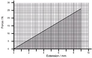
Fig. 1. Force vs. Extension graph for helical spring-(spaceflight.esa.int)
2.3 Transmission Assembly
The energy stored in a compressed spring is directly propor- tional to the extent of compression. As the spring relaxes the energy released by it decreases linearly. In order to make the energy release uniform, a toroidal continuously variable transmission (CVT) has been used. As the energy released by the spring decreases linearly, the gair ratio of the cvt is also correspondingly varied (lowered) to maintain the output shaft at a constant rpm.
Advantages of using a toroidal CVT;
1. High reliability thus requiring lesser maintenance and
providing longer service
2. Infinite gear ratios, thus providing a constant output.
3. High efficiency
4. Compact size and lower weight
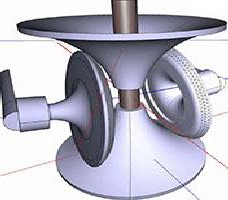
Fig .2. Toroidal CVT (http://www.engr.iupui.edu)
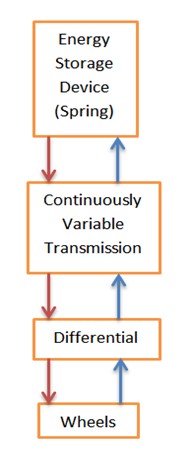
Fig. 3. Storage and release sequence.
2.4 Electronic Control Unit
In this system, the electronic control unit acts as the command center for rest of the mechanical systems. The functions that will be served by the unit are-
1) Controlling the action of CVT so that constant RPM is
maintained during the power release phase.
IJSER © 2013
http://www.ijser.org
International Journal of Scientific & Engineering Research, Volume 4, Issue 4, April-2013 1191
ISSN 2229-5518
2) To control the time at which the power stored in the
KERS will be released in automatic mode.
3) To accept trigger from the driver so as to use the en- ergy stored in spring in manual mode.
4) To determine the point at which the KERS system has to be disengaged so as to prevent over winding and eventual damage of spring.
5) To determine the nature in which the power will be supplied to the main drive train to obtain the maxi- mum efficiency.
.
3 SYSTEM WORKING
The electronic control unit of the system is responsible for timing the power absorption and release procedures. The power will be absorbed directly from the crown wheel of the differential of the vehicle using gears for power transmission from the differential to the power storing element i.e. the spring. However the power train consists of a continuously variable transmission so that the energy release and absorp- tion is uniform so that the mechanical parts are not damaged and also the system is safe to use.
A miter gear is used to transfer the power from the differential
to the CVT assembly which adjusts the input to pre-decided
rpm. The power from CVT is then sent to the secondary shaft of the system. The shaft has two spur gears which are free to rotate about the shaft unless engaged by the collar. The movement of the collar depends on whether power is being stored or released. If the power is being stored then the lower spur gear will be engaged by the collar so that the input power from secondary shaft is directly converted to the rotation of the gear. This gear is in turn meshing with another spur gear which is connected to the spring. Hence when the gear rotates, the spring is compressed to a particular limit as governed by ECU of the system. Power is hence stored in the spring. The collar then disengages from the spur gear.
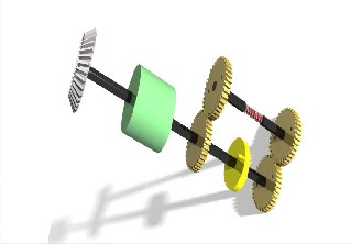
Fig. 4. Transmission Assembly
When the power enhancement of the vehicle is required or when the driver wishes to engage the KERS system then the
power collar shifts to the second gear on the secondary shaft. When the power is required by the user then signal from ECU causes the spring to unwind and hence rotate a spur gear. This spur gear is meshing with the second gear on the secondary shaft. The collar now shifts from the first gear to the second gear on the shaft, resulting in transmission of power from KERS to the main shaft via CVT.
4 ADVANTAGES
The advantages of using this system are-
1) The power storage is permanent and hence the power stored can be released whenever required.
2) Use of CVT ensures safe usage and higher life of me- chanical components
3) Use of the given gear arrangement allows power to be transmitted in the same sense of rotation as that of the main shaft.
4) The system is compact and can be mounted easily on vehicles
5 CHOICE OF PLATFORM
In this field of research, we have selected four wheelers particu- larly because-
1) The KERS system can be mounted easily
2) Latest pollution control norms require better fuel effi-
ciency of four wheeled vehicles.
3) Four wheelers are the most widely uses modes of transport and the use of this system will result in a huge impact.
6 CONCLUSION
The aim of this system is to increase the fuel efficiency of the system and also the performance of the vehicle by storing the energy which has been lost during braking in a spring and then using it when required. More research and development in this field will result in cost and size reduction of the compo- nents
References
[1] Kinetic Energy Recovery System by means of flywheel en- ergy storage
- J Cibulka
[2] Spring and Gear design, Design Data Handbook
-K.Mahadevan, K.Balveera Reddy
IJSER © 2013
http://www.ijser.org