International Journal of Scientific & Engineering Research, Volume 2, Issue 11, November-2011 1
ISSN 2229-5518
Investigation on Octagonal Microstrip Antenna for
RADAR & Space-Craft applications
Krishan Kumar, Er. Sukhdeep Kaur.
Abstract : In this paper octagon shape planar microstrip antenna is presented. Octagonal antenna can find applications in Radar and Space-crafts. The antenna is fed by a 50 Ω microstrip line and printed on a dielectric Fr4 substrate of dimension (22mm X 22 mm) perm ittivity εr =4.4 and height h = 1.6 mm. The optimization on the planar octagonal microstrip has been done to accomplish an -10 dB return loss bandwidth. Moreover, in comparison with a simple rectangular shaped antenna, the proposed design enhances the bandwidth and improves input return loss. Better than 83.54 % radiation efficiency has been achieved in the range 3.1 to 15 GHz. The parameters like substrate dimension, feed size and ground plane which affect the performance of the antenna in terms of its frequency domain and time domain characteristics are investigated.
—————————— ——————————
ICROSTIP antenna technology has progressed a lot and is still emerging in the field of radar , space-craft
,wireless & mobile communication. It has created increased interest in the planar forms of the MSA antennas can also be integrated between the radio frequency (RF) front end circuitry and the radiating structure. The simplest way to implementing planar forms of the antenna is using the microstrip feeding technology, which is widely used in radar & Space-craft applications.
Microstrip antenna in its simplest form consists of
a radiating patch on one side of a dielectric substrate and a ground plane on the bottom side of the substrate. However, many other shapes, such as the square, circular, triangular, semicircular, hexagonal, and annular ring shapes are also used. Microstrip antennas are popular because of its compact size, light weight, low cost, low profile, high efficiency and economical fabrication features [1], [2]. Out of the different forms the simplest form of the microstrip antennas is the microstrip slot antenna, which radiates omni-directional radiation patterns. Microstrip slot antennas fed by a microstrip line have shown wideband and ultra wideband performances [3][4].The simulation results of antenna design were obtained by employing the Ansoft Corporation High Frequency Structure Simulator (HFSS) v11.0 tools, which are finite element method (FEM), based commercial full wave analysis programs [5].
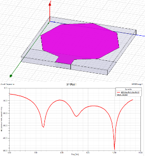
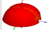
A. Antenna Geometry: Fig. 1 illustrates the evolution of
the proposed Microstrip Antenna on the Fr4 substrate.
Fig. 1 The proposed Octagonal Microstrip antenna (a) Simulation Model Fig.2.The reflection coefficient (S11, dB) versus frequency (GHz) plot for antenna design.
From the simulations & measurements of the microstrip antenna the optimized dimension are 22 mm x 22 mm (l x b) and thickness of 1.6mm. The offset feeding strip is generally 1.6 mm thick. Fig.1 (a) shows the microstrip antenna with octagonal structure and finite system ground plane. However the Efficiency Vs Frequency characteristics of microstrip antenna vary for the different frequency of simulation. In order to further reduce the overall size of the microstrip antenna structure a slot can be cut at the
IJSER © 2011 http://www.ijser.org
International Journal of Scientific & Engineering Research, Volume 2, Issue 11, November-2011 2
ISSN 2229-5518
octagonal radiator. As an example the microstrip antenna
fabricated on a Fr4, εr=4.4 & 1.6 mm in thickness. The position of feed point to the antenna structure can be varied to vary the result. The microstrip antenna substrate is enclosed in a radiation box. The radiation box of the antenna is generally larger in dimension (lxb) and it is approximate four times larger in height. The antenna structures are then assigned with the analysis set-up which encloses solution frequency, start & stop frequency of simulations, step size, Max. no. of passes etc..It should be noted that in the simulation process the microstrip antenna design structure was feed by a microstrip feeding with a 50 ohm internal resistance which is provided without any RF feeding cables. The ground plane size selection is also based on the study presented in [6], [7] on the microstrip slot antennas.
The electric field distributions of the octagonal microstrip antenna at the different frequency of simulation (5 GHz, 10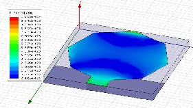
GHz & 15 GHz) are demonstrated as below: At 5 GHz
At 10 GHz
At 7 GHz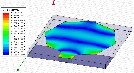
At 15 GHz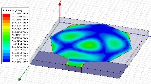
Fig. 3illustrates the simulated current distributions on the antenna at (a) 5GHz (b) 10 GHz (c) 15GHz
At 5 GHz, it can be observed that the majority of the electric currents is concentrated except around the central portion of the radiator Therefore, the effects of the RF cable and ground plane on the antenna performance at the lower frequencies can be minimized effectively[8]. At higher frequencies, most of the electric currents are distributed on the feeding strip, the junction of the heptagonal radiator, and the top strip. As a result, the currents on the ground plane are stronger than those at 5 GHz. At 15 GHz the field distribution are stronger as compared to 5 GHz. Feed size of antenna operates as a impedance matching circuit. Consequently, the feed gap greatly affects the impedance matching.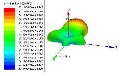
IJSER © 2011 http://www.ijser.org
International Journal of Scientific & Engineering Research, Volume 2, Issue 11, November-2011 3
ISSN 2229-5518
dB(rEPh1)
1. 18561!+001
-2. 7970e:+001
-6. 7796 e +001
-1. 07621!+002
-1. lt71f5e+002
-1. 8728e+002
-2. 27101!+002
-2. 6693e +002
-3. 06751!+002
-3. "1658e+002
-3. 86'+11! +002
-'+. 26231!+002
-'+ . 6606 e+002
-5. 05891!+002
-s. '+S71e:+002
-5. 855'+1! +002
-6. 2537e+002
d8(rE2')
1. 7134 e +001
1. 3848e +001
1.0562e +001
7. 2759e +000
3. 9899e +000
7.0381e-001
-2.5823e +000
-5. 8683e +000
-9.1 544 e +000
-1. 24 40e +001
-1.5727e +001
-1. 9013e +001
-2. 2299e +001
-2.SS85e +001
-2. 8871e +001
-3. 2157e +001
-3.5443e+001

dB ( rEThe'ta)
1_ 71"'l.fi':+AI?I1 z
.1. 't 7 9 Ch:::...0B.1
1.21.f 63e+001
:1.B:t.2 7••09:1
-8. 5580 ·000
-.1.00 9'to;:: ...00.1_
-1. 3229e +001
-:1- ssss·e<a:t
-:1.79ell.e+001
-2.0236e +001
z
1. 2SS8e+0e1
8. SG0')e • 000
'90G 0e•OC1.
Z: 't0-'e+E'ti::I:L
-- ::ltiFide+1:11:::1:l
-1.11.f9'ie+002
-1. 3621e+00 2
-1.. 5747e+B02
-1.. 787 4e+B02 y
-2.0001e+002
-2. 212 7e+002
-2.42S'+e+0e2
-2. 6381e+0e2
-? _ A."W''R""+"'A ?
-3_ 06'91.f ..•G121 2
-3. 2761.e• 092
1. 3066e+001
l.f'+'+3e+000
9957e+001
-s . 1 '+69 e+001
-7 . 2982 e+001
-9. l.f'+95e+001
-1. 1601e+002
-1. 3752e+002
-1. 5903e+00 2
-1. 605'te+002
-2. 0206e+002
-2 . 2357e+002
-2 . 4506e+002
-2. 6660e+002
-2. 8611e+002
-3. 0962e+002
-3. 3113e+002

![]()
9. 0983e +000
-1. 19Lt6e +001
![]()
![]()
-3. 2990e +001
-s. 403Se +001
-7. 5e79e +001
-9. 6123e +001
-1.1717e +002
-1. 3821e +00 2
-1. 5926e +002
-1. 0030e +002
-2. 013Se +002 y
-2. 2239e +00 2
-2. 43Lt 3e +002
-2. 64 Lt8e +002
-2. 8552e +002
-3. 0657e +002
-3. 2761e +002

1. 412'+e +001
1. 2'+19e+001
1. 0711+e +001
9. 0063e+000
7. 3032e+000
S. S960e+000
3. 6929e+000
2. 1877e+000
4. 8253e-001
-1. 2226e+000
-2. 9278e+000
-'+ . 6330e +0021
-6. 3381e+000
-B. 04 33e+000
-9. 748Se+00121
-1. 1'+5'+1!+001
-1. 3159e+001

_J,_ , 't.l. 2:7o;:...aeJJ_
:1. 2'+1 2e +001
1 .86 :7-•801
1:1 . ':lt11':1e + <Mid
7. 2668e•000
:::;; • .:::;:::;1; 7e...efle
3. 8366e•000
?_ 1 ?1_c:;;... l?ll?ll?l
-3 . "'238e•0Ca0
-<t . 730'3e +000
-6 . '+5'+0e +000
8. 16'31c • 000

1. 713'+ e +001
-3. 4691e•000
-2. 4072e+001
-4 . 4675e• 001
-6.5279e•001
-8.5882e+001
-1.0649e• 002
-1. 27e9e+002
-1. 4 769e+002
-1. 6829e +002
-1, 6890e+002
-2.09.50e+002
- 2.3010e +002
-2..5071e+002
-2. 7131e +002
-2. 9191e•002
![]()
-3.1252e+002
z
y
z
---._y
y
![]()
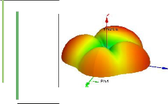
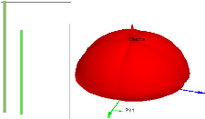
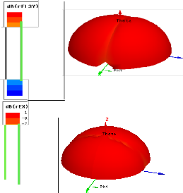
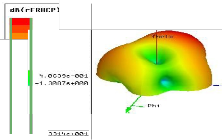
Fig.4 illustrates the effect of the different radiation pattern of Microstrip antenna.
IJSER IS) 2011
International Journal of Scientific & Engineering Research, Volume 2, Issue 11, November-2011 4
ISSN 2229-5518
This design of a compact size octagonal microstrip antenna
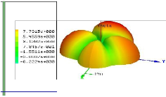
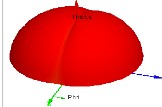
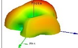
suitable to be used in mobile devices, where a three- dimensional (3-D) omni-directional radiation and high radiation efficiency are desirable. The 3-D radiation patterns for total radiated electric fields were measured at frequencies of 7 GHz ,where the red colour indicates the stronger radiated E-fields and the blue colour the weaker ones. It is seen from the figure that the radiation at 7 GHz is almost 3-D omni-directional, because the x and y– components of the electric currents on the antenna are both strong as shown in Fig. 4(a). The radiation pattern of antenna is slightly weak along the –y and –x axis directions. With the measured 3-D radiation patterns, the radiation efficiency can be attained. The measured radiation efficiency varies from 18.98 % at 3 GHz to 94.26% at 12GHz.
The directivity of the microstrip antenna can also be calculated with the following mathematical relationship:
D = 2.2W+6.6+10 log (![]() )
)
The gain of the antenna structure can be calculated as the mathematical derivation:
Gain = 4Π (![]() )
)
U: Radiation intensity in W ![]() : Accepted Power in w
: Accepted Power in w
Furthermore the efficiency of the antenna structure in its
symmetrical form can be estimated. The efficiency of the microstrip antenna can be expressed in terms of the peak directivity & peak realized gain of the antenna.
Efficiency = ![]() * 100
* 100
The VSWR or impedance BW of the microstrip antenna is defined as the frequency range over which it is matched with that of the feed line within specified limits. The BW of the microstrip antenna is inversely proportional to its quality factor Q and is given by
BW = ![]()
where VSWR is defined in terms of the input reflection
coefficient г as:![]()
VSWR =
The г is a measure of reflected signal at the feed-point of the antenna. It is defined in terms of input impedance Zin of the antenna and the characteristic impedance Z0 of the feed line as given below:
г = ![]()
The BW is usually specified as frequency range over which
VSWR is less than 2 (which corresponds to a return loss of
9.5 dB or 11% reflected power).
From the below graph of Frequency Vs Efficiency it has been observed that the max. efficiency of antenna i.e ( 84.53
%) obtained at 2 GHz & min. 63.35 at 15 GHz.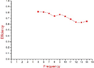
Fig. 5 The frequency (GHz) versus efficiency plot for the
Microstrip antenna design
From the below Graph of Frequency Vs Gain it has been observed that the max. gain of microstrip antenna i.e 4.65 obtained at 14 GHz.
IJSER © 2011 http://www.ijser.org
International Journal of Scientific & Engineering Research, Volume 2, Issue 11, November-2011 5
ISSN 2229-5518
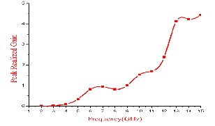
Fig.6 The frequency (GHz) versus Gain plot for the
Microstrip antenna design
A Effect of Substrate Material Fr4 & Roger4003 on S Parameter
In this antenna design we are taking the substrates Fr4 & Roger4003to calculate their effect on performance. From the below graph it has been observed that use of Fr4 as a substrate satisfy the -10dB return loss. With Fr4 first lobe of
-37dB occur at 7.2 GHz whereas with Roger4003 the first lobe of return loss of -30dB at a frequency of 8GHz. The use of Fr4 as a substrate provides the min. return loss of -43 dB at 10GHz whereas with Roger4003 the min. loss of -30dB at
8GHz. So it can be concluded that Fr4 act as better substrate material for satisfying the return loss.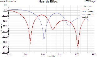
Fig.7.The reflection coefficient (S11, dB) versus frequency
(GHz) plot with FR4 &Roger4003 as a substrate material for the Microstrip antenna design
In this design of antenna we are taking two substrates to
calculate their effect on efficiency , realized gain & calculation of S11 parameter. With the use of FR4 as substrate the max. efficiency of antenna 94.26 % has been obtained whereas the use of Roger4003 as a substrate there is a reduction in efficiency i.e 87.49% .With Roger as a substrate there are also reduction in lobe size in the calculation of S11 parameter. With the use of Fr4 the max. peak realized gain of 4.65 has been obtained whereas the use of Roger4003 as a substrate reduces the max. peak realized gain to 3.4.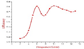
Fig.8The frequency (GHz) versus efficiency plot with FR4 as a substrate for the Microstrip antenna design
B Effect of Substrate thickness:
In this antenna design we are taking the different substrate thickness to analyse its effect on performance of antenna. In accordance with FCC rules & standards of microstrip antenna substrate thickness < 2mm to maintain the compactness of antenna.In this antenna design the substrate thickness of 1.6 mm provides the -10dB return loss requirements. With substrate thickness of 1 mm the antenna design requirement of -10dB return loss does not met.
IJSER © 2011 http://www.ijser.org
International Journal of Scientific & Engineering Research, Volume 2, Issue 11, November-2011 6
ISSN 2229-5518
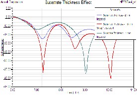
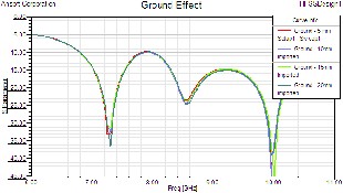
Fig.10.The reflection coefficient (S11, dB) versus frequency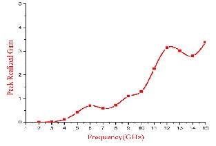
(GHz) plot with Ground size of 5,10,15 & 20 mm for the
Microstrip antenna design.
Fig.9 The frequency (GHz) versus Gain plot with Roger4003 as a substrate for the Microstrip antenna design.
C. Effect of Ground Size on performance:
In this design variation of ground size has a little effect on the efficiency. The S parameter value also have a little variation due to ground size. So it can be concluded that the ground size have small effect on the performance of antenna. In this antenna design we are taking the different size of ground to investigate its effect on performance of antenna. In this design we are taking ground size of 5, 10,
15 &20mm.From the below graph it has been concluded that the variation of ground size has a negligibly small effect on antenna performance.
At 5,10,15 & 20 mm
D Effect of Feed size on antenna performance: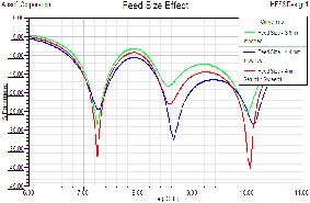
In this design of microstrip antenna we are taking the different feed size to calculate their effect on performance. The feed size of antenna influences the impedance of antenna. In this antenna design the feed size of 4mm satisfy the requirement of -10dB. The feed size has inversely proportional effect with the port impedance. With increase in feed size of antenna the input impedance of antenna decreases.
IJSER © 2011 http://www.ijser.org
International Journal of Scientific & Engineering Research, Volume 2, Issue 11, November-2011 7
ISSN 2229-5518
In this paper, a planar octagonal shape microstrip slot
antenna is investigated for the impedance matching and radiation pattern characteristics. The antenna can find applications in radar & Space –craft applications. However, the antenna designs almost met the frequency range requirements and provides the omni-directional patterns. From the octagonal microstrip antenna design it has been observed that the max. omni-directional pattern is obtained at the central solution frequency (7 GHz) of simulation.
Investigations have also been carried out in this paper to analyze the design parameters of octagonal Microstrip Antenna. With the use of octagonal as a radiating element in UWB antenna efficiency up-to 94.26% has been achieved. Octagonal Microstrip antenna can also provide directivity up-to 4 & impedance bandwidth > 110% as the requirement of UWB technology [9]. The feed size of antenna is inversely proportional to the port impedance. The dimension of the microstrip antenna also has an impact on the antenna performance because the current is mainly distributed along the edge on the radiator. In a broad sense, the ground plane of the antenna design perform operation as an impedance matching circuit, and it tunes the input impedance and hence changes the operating bandwidth with variation of antenna feed size. Octagonal microstrip antenna provide the characteristics with nearly omnidirectional radiation patterns over the entire bandwidth.
I would also like to thank Er. Naresh Kasnia Assistant Professor at JCDM College of Engineering, Sirsa for their help to provide the basic knowledge about the software HFSS 11.
[1] R Garg, P. Bhartia, I. Bahl, and A. Ittipiboon, Microstrip
Antenna Design Handbook.Norwood, MA: Artech House,
2001.
[2] J. L. Volakis, Antenna Engineering Handbook, 4th ed. New York: McGraw Hill, 2007.
[3] A. A. Eldek, A. Z. Elsherbeni, and C. E. Smith,
“Microstrip-fed printed lotus antenna for wideband wireless communication system,” IEEE Antennas Propag. Mag., vol. 46, no. 6, pp. 164–173, Dec. 2004.
[4] A. M. Abbosh, M. E. Bialkowski, J. Maziersha, and M. V. Jacob, “A planar UWB antenna with signal rejection capability in the 4–6 GHz band,” IEEE Microw. Wireless Co
[5] Ansoft Corporations, Designer and High Frequency Structure Simulator (HFSS) [Online]. Available: www.ansoft.com
[6] S. I. Latif, L. Shafai, and S. K. Sharma, “Bandwidth enhancement and size reduction of microstrip slot antennas,” IEEE Trans. Antennas Propag., vol. 53, no. 3, pp.
994–1003, Mar. 2005.
[7] Y. F. Liu, K. L. Lau, Q. Xue, and C. H. Chan, “Experimental studies of printed wide-slot antenna for wide-band applications,” IEEE Antennas Wireless Propag. Lett., vol. 3, pp. 273–275, 2004
[8] Zhi Ning Chen, Senior Member IEEE & Terence S. P See and Xianming Qing “Small printed UWB Antenna with reduced Ground Plane effect” IEEE transactions on Antenna & Propagation Vol. 55 No. 2, February 2007
[9] Sunil Kumar Rajgopal and Satish Kumar Sharma, Senior Member, IEEE “Investigation on UWB Pentagon Shape Microstrip Slot Antenna for Wirelss Communications” IEEE Transactions On Antenna And Propagation, Vol. 57, No.5, May 2009.
IJSER © 2011 http://www.ijser.org