International Journal of Scientific & Engineering Research, Volume 6, Issue 1, January-2015
ISSN 2229-5518
1932
SUMIT SHARMA, AJAY SHARMA*
*Department of Mechanical and Automation Engineering
ASET, Noida, Amity University Uttar Pradesh.
The sliding of metal parts when they are unlubricated is important in many mechanical devices covering a wide range of velocities, but the sliding velocity of the unlubricated metals which are tribological in behavior. A tribometer is an instrument that measures the tribological properties such as co-efficient of friction, wear volume between two surfaces in contact2, 8. There are various types of tribometer four ball, pin on disc, block on ring, bouncing ball and twin disc. In this paper we have focused or taken aluminum (Al) disc and other mating part is of high speed steel (H.S.S) pin which makes point contact, which is a very common combination. With the help of the
apparatus we find different variations such that load and wear rate and time and wear rate variations when load is constant and also pin radius and wear rate variations. In this paper, we calculate the wear rate by using two equations such as Archards equation considering the wear rate with respect to the time and also by using the Archards and Holm equation considering the wear rate with respect to the sliding speed and volume loss. These wear testers are generally used in light truck brake pads, on railway tracks, disc brakes.
Wear can be defined as the phenomenon of removing the material from the surface due to interaction with a mating surface. There is a fact that almost all the machines due to wear lose their durability and reliability. Hence there is a possibilities of inventing new machines which are more advanced are reduced because of wear problems. Wear rates can be changed drastically between the range of (10-15-10-1)
mm3/Nm which depends upon the selection of the materials, components and methods
used. Wear can be either good or bad. Examples of productive wear are shaving, writing with a pencil, polishing. Wear is undesirable in almost all machine application
IJSER © 2015 http://www.ijser.org
International Journal of Scientific & Engineering Research, Volume 6, Issue 1, January-2015
ISSN 2229-5518
1933
such as bearings, seals, gears and cams. In well designed tribological system, the removal of material is a very slow process but it is very continuous, and steady. Many of us would think that it is the property of material but fact is that it is not the property of the material but it is a complex response of the material in which it operates to the solicitations induced by the systems. Many scientists are working on wear phenomenon from many years. (Burwell-1957/1958, Kragelski-1965, Engel, Eyre-
1976, Suh-Saka-1980, Rigney-1981, Loomis-1985, Hutchings-1992, Bayer-1994, Rabinowikz-1995, Bhushan-1996, Shipley and Becker-2002). The foreign wear machines are costly, rarely available in the market and beyond the reach of the researchers which cannot be very easily affordable3, 6, 5, 9. Hence it is necessary to evolve effective machine with perfect materials and components which will be cheap and readily available in the market and will improve good quality control, good
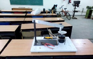
manufacturing practice, and productivity in building the industries and also by evolving these machines it would increase our National Economical Growth and would contribute in the progress of our country. Hence for this purpose we make pin on disc apparatus in which the pin is in continuous contact with the rotating disc when we applied the constant normal load. . In this operation the weight loss is continuously measured and by the help of which we can find the wear rate using Archards Equation. We also calculate the wear rate by considering the volume loss of the materials. The aim of our project is to evaluate the effect of load and wear variation; also evaluate the time and wear variation on the same load; and also evaluate the pin radius and wear variations by considering the weight losses and volume losses.
The first method that we have used to find the wear rate is Archards Equation. By using this equation we have find the wear rate with respect to time and the unit of
wear rate is mm/sec. The Archards Equation1 is given as-: m’/p.v.t.A
Where m’- weight loss which is in gm; p- Average density of aluminum; v- Velocity at which the disc is rotating or the velocity at which the motor is running; t-
Time; A-Area when the pin is just touching the disc or apparent area;
IJSER © 2015 http://www.ijser.org
International Journal of Scientific & Engineering Research, Volume 6, Issue 1, January-2015
ISSN 2229-5518
1934
Now for more accuracy and also we want to find the wear rate on the basis of the volume loss of the material not considering the wear rate with respect to time. Then, we have used Holm and Archards Equation4 which is given as -:
Q = k W/3 p = k W/ H and unit is mm/met.
Where Q is given as wear rate; k is the wear coefficient; W is the normal load; H is the hardness;
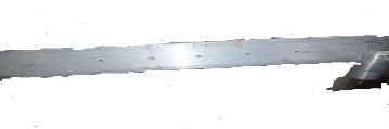
Fig1: Aluminium Flexible Arm

IJSER © 2015 http://www.ijser.org
International Journal of Scientific & Engineering Research, Volume 6, Issue 1, January-2015
ISSN 2229-5518
1935
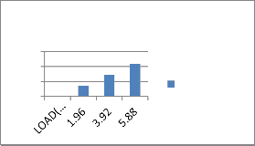
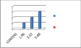
1.) We have found the wear rate with respect to the changing of load using weight
loss and volume loss of the material. For first hole
1500
1000
500
0
WEAR(MM/S EC.
0.4
0.3
0.2
0.1
0
WEAR(mm^3
/met.)
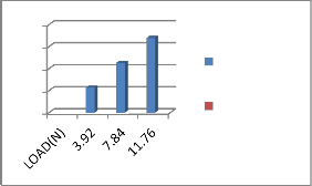
For second hole
1500
1000
500
0
WEAR(MM
/SEC.
0.4
0.3
0.2
0.1
0
WEAR(mm^3
/met.)
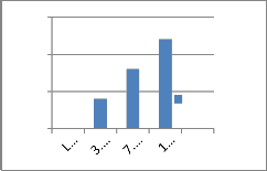
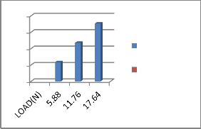
For third hole

1500
1000
500
0
WEAR(MM/ SEC.
0.4
0.3
0.2
0.1
0
WEAR(mm^3/
met.)
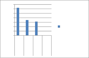
(B) Graph between time and wear for different holes
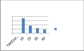
2.) We have found the wear rate with respect to time considering the weight loss.
For first hole
400
300
200
100
0
WEAR(mm/sec
.)
IJSER © 2015 http://www.ijser.org
International Journal of Scientific & Engineering Research, Volume 6, Issue 1, January-2015
ISSN 2229-5518
1936
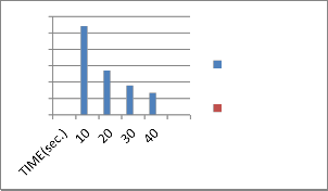
For second hole
800
600
400
200
0
WEAR(mm/se c)
For third hole
1200
1000
800
600
400
200
0
WEAR(mm/sec
.)
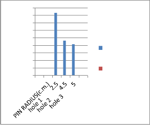
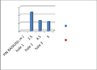
3.) We have found the wear rate with respect to the pin radius on holes considering weight loss and volume loss.
© Graph between pin radius and wear for different holes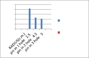
For first hole
500
400
300
200
WEAR(mm/sec
0.12
0.1
0.08
0.06
0.04
0.02
100
0
.) 0
WEAR(mm^3/m
et.)
IJSER © 2015 http://www.ijser.org
International Journal of Scientific & Engineering Research, Volume 6, Issue 1, January-2015
ISSN 2229-5518
1937
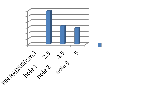
For second hole
900
800
700
600
500
400
WEAR(mm/se
0.3
0.2
0.1
WEAR(mm^3/me
300
200
100
0
c.) 0
t.)

For third hole
1400
1200
1000
800
600
400
200
0
2.5 4.5 5
WEAR(mm/sec
.)
0.4
0.3
0.2
0.1
0
WEAR(mm^3/
met.
hole
1
hole
2
hole
3
Result
After making calculations and drawing the graphs by using both the two methods we have found that:
As the load increases then the wear rate also increases and as the load decreases, the wear rate also decreases when we lift the weights on the same hole or on the different holes.
As the time increases, the wear rate decreases and as the time decreases, the wear rate increases when we lift the weights on same holes and when we lift the weights on the different holes then as we increase the time, the wear rate
also increases and as the time decreases, the wear rate also decreases.
IJSER © 2015 http://www.ijser.org
International Journal of Scientific & Engineering Research, Volume 6, Issue 1, January-2015
ISSN 2229-5518
1938
By fixing the holder pin at different holes, wear rate increases.
By fixing the holder pin at different holes and by putting the same load the wear rate decreases.
As the pin radius increases, the wear rate decreases on the same load and as the pin radius decreases, the wear rate increases on the same load.
If the pin radius is at the same hole then applying different loads and as loads increases, the wear rate also increases.
Conclusion
![]() We have found different variations of wear rate with respect to the loads, time, holder pin, and pin radius.
We have found different variations of wear rate with respect to the loads, time, holder pin, and pin radius.
![]() We have also successful in achieving our objective or aim to find out the accuracy of our readings, wear tester as compare to the results of the other researchers.
We have also successful in achieving our objective or aim to find out the accuracy of our readings, wear tester as compare to the results of the other researchers.
![]() We have got the perfect accuracy of the wear rate as compare to the foreign wear tester. We have developed our tester at small scale which gives the perfect values of the wear rate as compare to the large tester machines.
We have got the perfect accuracy of the wear rate as compare to the foreign wear tester. We have developed our tester at small scale which gives the perfect values of the wear rate as compare to the large tester machines.
Implications for future research:
By making some more corrections like selection of the perfect materials, and maintaining the working temperature it would be the successful analytical tool which can be used to measure the wear rate.
By the addition of temperature sensor and a digital display device can also help us to know the characteristics of temperature with wear and friction.
By using paced sensors, wireless devices, we can improve the life span and quality of the wear testing machine.
By doing the study on wear testers we have come to know the by the mixing or use of the ceramics, polymers, plastics, crystalline materials in the metals and components we will obtain perfect materials and components for the making of the perfect wear testers because these all materials have some in them which would help in building the perfect metals and components which would further help in making the accurate, perfect wear tester on a small as
well as large scale.
IJSER © 2015 http://www.ijser.org
International Journal of Scientific & Engineering Research, Volume 6, Issue 1, January-2015
ISSN 2229-5518
1939
References:
[1] Amal Ebrahim Nassar and Eman Ebrahim Nassar, Design and Fabrication of a Wear Testing Machine, Leonardo Electronic Journal of Practices and Technologies (ISSN 1583-1078), 19 July- December 2011 p.39-48
[2] Ajay Sharma, Narendra Singh, P.k. Rohtagi, Study of Wear Pattern and Behaviour of Aluminum and Mild Steel Discs using Pin on Disc Tribometer, European Journal of Applied Engineering and Scientific Research, 2013 2(4): 37-43
[3] Bharat Bhushan, Introduction to Tribology ( John Wiley and Sons, New York, 2002)
[4] Surfaces, Interfaces and their Applications-2 (Introduction to Wear) – Nicholus Spencer
[5] Kenneth C. Ludema, Friction, Wear, Lubrication: A textbook in Tribology (1996)
[6] Designation: G99-95a (Reapproved 2000), Standard Test Method for Wear Testing with a Pin on
Disc Apparatus
[7] Tribology International Vol.29 NO. 5, PP. 415-423, 1996, Characteristics of Wear results tested by
Pin on Disc at moderate to high speeds
[8] Intensity of Interactions – Friction, Wear and Lubrication (1918)
[9] Wear Mechanisms (Kodi Kato and Koshi Adachi, Tohoku University), 2001
IJSER © 2015 http://www.ijser.org