INTRODUCTION
I
N these days the demand of multiband antennas are in- creasing rapidly in various communication services like:- (a) WiMAX (Worldwide Interoperability for Microwave Ac- cess) (b) WLAN (Wireless Local Area Network) (c) GSM(Global System for Mobile communications) (d) UMTS (Universal Mobile Telecommunications System) (e) DCS (Digi- tal Communication Systems) and many other wireless appli- cations.These wireless communication services require the broadband and multiband antennas in place of narrowband
antennas for better performances [1].
So, the modern wireless communication devices want the sin-
gle one antenna which can operate more than one frequency
band. For multiband operation mainly ultra wideband anten-
na is designed. When antenna works for the good perfor-
mance then the miniaturization is the main issue in these an-
tennas. To minimize this issue in multiband antennas we use
the planar printed monopole antennas due to its simple struc-
ture and low cost, these antennas also have the feature of ease
of fabrication, wide bandwidth and Omni-directional radia- tion pattern [2],[3],[4],[5],[6],[7].
Bandwidth also a main parameter in the multiband antennas so there are so many techniques are use for increasing the bandwidth of these antennas . Some techniques use in the ground plan of the antenna like L-shaped notch in the lower corner is use in the truncated ground plane [8],[9] and in the middle of the ground an inverted T-shaped notch in the mid- dle of the truncated ground plane is used for enhancing the bandwidth of the antenna[10].
Recently, the enhancement of the resonant frequency band also become popular parameter in the communication devices for this two slot are used in the ground plane and the band- width of antenna is also enhanced [11].
These antennas are not sufficient for filling the all requirement of the multiband operation so for increasing the band of the antenna a new technique used in this is a T-slit on the top of
PRPOSED ANTENNA DESIGN
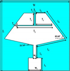
The proposed diamond shaped microstrip patch antenna is fed by the rectangular feeding line with the quarter wave transformer as shown in Fig.1.This proposed antenna is print- ed on the FR-4 substrate with the dimension of 22 X 16 mm2 and the thickness of 1 mm. The FR-4 substrate which is used for the designing of antenna has the relative permittivity of
4.05 with the loss tangent of 0.02.
The diamond shaped antenna has the inverted T-slot on the
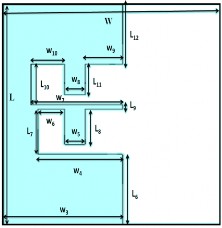
radiating patch and the E-slot in the partial ground of the an-
tenna. The microstrip feeding line is fixed at the width W2 = 0.7mm and the length L2 = 4 mm. The length of the quarter wave length transformer has L1 = 4 mm and the width W1 =3mm is used for the impedance matching between the
input port of the signal and the output port of the signal to
the radiating patch of the antenna. The matching impedance of the proposed antenna structure is 60.67 ohm.
The diamond shape patch antenna with full ground is oper- ate signal band of frequency when there is no inverted T-slot in the patch when we use the inverted T-slot in the radiating patch of the antenna than it operates as the dual band antenna thus this T-slot is responsible second band of the antenna. Now we change the dimension of this T-slot and also design
IJSER © 2013
(a)
(b)
Fig. 1. (a) Proposed antenna design (top view), (b) Bottom.
TABLE 1
DIMANSIONS OF PROPOSED ANTENNA DESIGN
an E-slot in the radiating patch of the antenna than this anten- na work at the triple frequency band. These bands are cen- tered at the frequency 3.4069 GHz, 7.4132 GHz and the 10.678 GHz, these bands are useful for the communication applica- tion, the first band is cover the range of Wimax, second oper- ates at C-band and third band is used for the fixed satellite service.
The dimension of this inverted T-slot is responsible for the second and the third band of the antenna, these bands of fre- quency can be changed by the changing the dimension of the T-slot T2 , T3, T4, T5 and W .These bands also depends on the dimensions of the E-slot in the ground plan so they can also change by varying the parameter of the E-slot of the ground plan.
MODIFIED DESIGN OF PROPOSED ANTENNA
The modified structure of the proposed antenna is shown in the Fig.2. In this design the dimension of the E-slot of the ground plan is optimized and the T-slot of the radiating patch is fixed.
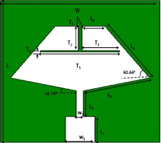
(a)
![]()
Antenna
Value Antenna
Value
parameter parameter
L 22mm T 3 3.8mm
L1 4mm T 4 0.2mm
L2 4mm T 5 8mm
L3 6.94mm W 16mm
L4 9.178mm W1 3mm
L5 2.3mm W2 0.7mm
L6 7mm W3 8.75mm
L7 4.5mm W4 6.25mm
L8 3mm W5 1.5mm
L9 0.5mm W6 2mm
L10 3mm W7 6.75mm
![]()
L11 6mm W8 1.5mm
![]()
T1 0.4mm W9 1.25mm
![]()
T2 3.8mm W10 2.5mm
(b)
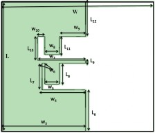
Fig. 2. (a) Modified antenna design (top view), (b) Bottom.
By changing the little dimension of the E-slot of the ground plan we increases the one frequency band of the proposed antenna and this modified structure workable up to four fre- quency band. This band is controlled by the dimension of the
IJSER © 2013
E-slot in the ground plan. This modified antenna covers the four frequency bands which are centered at the resonant fre- quency 4.4322 GHz, 5.3943 GHz, 8.6262 GHz and the 11.262 GHz. These bands are useful for the communication applica- tion, the first band is cover the range of 4generation system (4.6-5.2 GHz), second operates for WLAN(5.15-5.823 GHz) , third band is use for the ITU band application and the fourth band is used for the fixed satellite services(10.567-11.43 GHz).
TABLE 2
DIMANSIONS OF MODIFIED ANTENNA DESIGN
![]()
Antenna
Value Antenna
Value
parameter parameter
L8 3.5mm W4 4.55mm
![]()
W6 0.3mm W7 5.05mm W8 2.75mm W10 0.8mm
Fig. 4. VSWR of the proposed antenna structure.
RESULT AND DISCUSSION
The proposed antenna is simulated by the help of the Electromagnetic (EM) simulation software. The microstrip patch antennas are simulated and optimized with the help of this software. The E-field and H-field radiation patterns, VSWR, return loss, surface current and Gain of both antennas are discussed in this section.
Case-I Simulated Results of Proposed Structure
The designed proposed antenna works for the triple band of frequency with the operating frequency range from 3.4069 GHz to 10.678 GHz. These three bands of frequency are cen- tered at the 3.4069 GHz, 7.4132 GHz and 10.678 GHz and all bands are lies below than -10 dB so these bands are workable for the proposed antenna. The return loss of this antenna shows in the Fig.3.
From the Fig.3 it is very clear that this antenna is work at the resonant frequencies 3.4069 GHz, 7.4132 GHz and 10.678 GHz, which are useful for the Wimax, and fixed satellite service. The VSWR of this antenna is shown by the Fig.4 and this figure indicates that the impedance bandwidth of the proposed an- tenna.
The simulated radiation patterns of the proposed antenna are shown in the Fig.5, 6 and 7. The radiation pattern of the an- tenna is simulated for the E-plane and H-plane. These radia- tion patterns of the antenna are simulated for all the operating frequency of the antenna. From the Fig.5, 6 and 7 it is clear that the antenna is radiated in all direction because the radiation pattern of antenna is Omni directional in nature.
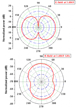
Fig. 5. Radiation pattern of proposed antenna structure at 3.4069 GHz.
The radiation pattern shown in Fig.5, 6 and 7 are shows the frequency band of 3.4069 GHz, 7.4132 GHz and 10.678 GHz respectively show the good agreement.
When the E-slot of the ground plan and inverted T-slot of the
Fig. 3. Return loss of proposed antenna structure.
IJSER © 2013

antenna has any change than the radiation pattern of antenna can be change linearly.The E-plane radiation pattern of the antenna is working as y-z plane with the feeding line and normal to the substrate of the antenna while H-plane radiation pattern in x-z plane working normal to the feeding line.
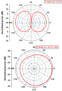
Fig. 6. Radiation pattern of proposed antenna structure at 7.4132 GHz.
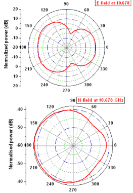
Fig. 7. Radiation pattern of proposed antenna structure at 10.678 GHz.
Fig. 8 shows the main parameter of the antenna, known as the antenna gain. The simulated gain of proposed antenna is cov- ering the range of frequency from 0 to 12 GHz. The gain of antenna for the 0-12 GHz is achieved from -20 dBi to 8 dBi.
Fig. 8. Gain of proposed antenna structure.
The surface current of the antenna is also a useful and im- portant parameter for the antenna. The Fig.9, 10 and 11 shows the surface current for the proposed antenna at the centered frequency at 3.4069 GHz, 7.4132 GHz and 10.678 GHz.
From the Fig.9 and 10 it is very clear that the mainly current flow in the antenna at the 3.4069 GHz and 7.4132 GHz is due to E-slot in the ground plan and this current flows from up- ward direction in the edges of the E-slot and downward to- wards the feeding line, at the edges of the E-slot the surface current is flows its maximum values while in the feeding line the surface current is reduce and there is very small current flows in the T-slot in the coming direction. At the center fre- quency 10.678 GHz, the current flow to the upward direction at its lowest value in the E-slot and the feeding line and these current flows up to its maximum value in the T-slot of the ra- diating patch in the outward direction.
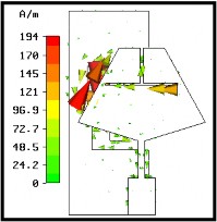
Fig. 9. Current distribution of proposed antenna structure at 3.4069 GHz.
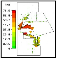
Fig10. Current distribution of proposed antenna structure at 7.4132 GHz.
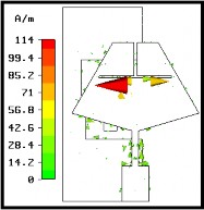
Fig. 11. Current distribution of proposed antenna structure at 10.678 GHz.
Case-II Simulated Results of Modified Structure
This modified antenna works for the four band of frequency with the operating frequency range from 4.432 GHz to 11.62 GHz. These four bands of frequency are centered at the 4.432 GHz, 5.39 GHz, 8.6278 GHz and 11.26 GHz and all bands are lies below than -10 dB so these bands are workable for the modified antenna. The return loss of this antenna shows in the Fig.12.
Fig. 12. Return loss of modified antenna structure.
From the Fig.12, it is very clear that this antenna is work at the resonant frequencies 4.432 GHz, 5.39 GHz and 8.6278 GHz and 11.26 GHz, which are useful for the 4G system, WLAN, ITU band application and the fixed satellite services.
The VSWR of this antenna is shown by the Fig.13 and this fig- ure also indicates that the impedance bandwidth of the pro- posed antenna.
Fig. 13. VSWR of modified antenna structure.
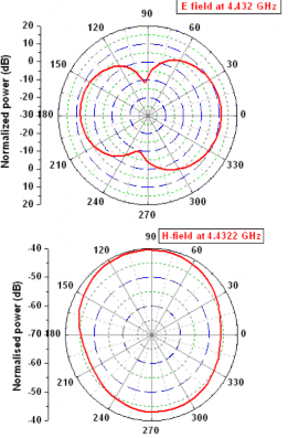
Fig. 14. Radiation pattern of modified antenna structure at 4.4322 GHz.
The simulated radiation patterns of the proposed antenna are shown in the Fig.14, 15, 16 and 17. The radiation pattern of the modified antenna is simulated for the E-plane and H-plane.
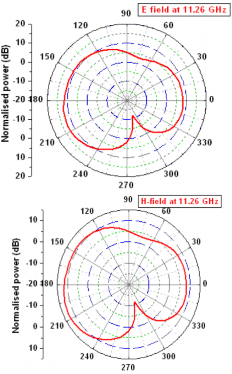
Fig. 15. Radiation pattern of Tetra-band antenna structure at 5.39 GHz. Fig. 17. Radiation pattern of Tetra-band antenna structure at 11.26
GHz.
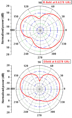
Fig. 16. Radiation pattern of modified antenna structure at 8.6278 GHz.
These radiation patterns of the antenna are simulated for all the operating frequency of the antenna. From the Fig.14, 15, 16 and 17 it is clear that the antenna is radiated in all direction because the radiation pattern of antenna is Omni directional in nature.
Fig. 18. Gain of modified antenna structure.
The radiation pattern shown in Fig.14, 15, 16 and 17 are shows the frequency band of 4.432 GHz, 5.39 GHz, 8.6278 GHz and
11.26 GHz respectively show the good agreement When the E-slot of the ground plan and inverted T-slot of the antenna has any change than the radiation pattern of antenna can be
change linearly. The E-plane radiation pattern of the antenna is working as y-z plane with the feeding line and normal to the substrate of the antenna while H-plane radiation pattern in x-z plane working normal to the feeding line.
Fig. 18 shows gain parameter of the antenna. The simulated gain of proposed antenna is covering the range of frequency from 0 to 12 GHz. The gain of antenna for the 0-12 GHz is achieved from -20 dBi to 8 dBi.
The surface current of the antenna is also a useful and im- portant parameter for the antenna. The Fig. 19, 20, 21 and 22 shows the surface current for the proposed antenna at the cen- tered frequency at 4.432 GHz, 5.39 GHz, 8.6278 GHz and 11.26 GHz.
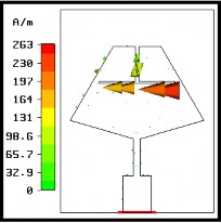
Fig. 19. Current distribution of proposed antenna structure at 4.4322 GHz.
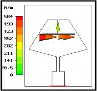
Fig. 20. Current distribution of proposed antenna structure at 5.39 GHz.
From the Fig.18 and 19 it is very clear that the mainly current flow in the antenna at the 4.432 GHz, 5.39 GHz and 11.26
Fig. 21. Current distribution of proposed antenna structure at 4.4322 GHz.
Fig. 22. Current distribution of proposed antenna structure at 8.2678 GHz.
GHz is due to inverted T-slot in the radiating patch and this current flows clockwise direction in 4.432 GHz, and anti- clockwise in 5.39 GHz, the current flowing at this frequency is very strong current and there is a very small current flowing in the edges of the E-slot in the ground plan. At the center fre- quency 8.6278 GHz and 11.26 GHz a very small current is flowing in the inverted T-slot and there is also a small current flowing in the E-slot of the ground plan.
4.3 Case-III Comparision of Case-I and Case-II
Fig. 23 shows the comparison of the simulated return losses of the proposed and modified structure of the antenna. From the above Figure it is clear that by the modified the E-slot of the ground plan the numbers of the frequency bands are in- creased.
Fig. 23. Comparison of return losses of proposed and modified struc- ture.
FABRICATED STRUCTURE AND RESULTS
Both antennas proposed and modified shown are fabricated on the FR-4 substrate. For designing of these structure FR-4 substrate of thickness h = 1 mm with Dielectric constant = 4.05 and loss tangent of the antenna is 0.02 is used.
For the measurement of the both antennas the vector network analyzer is used. The fabricated proposed and measured an- tenna structures are shown in Fig. 24.
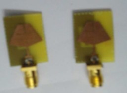
(a)
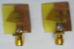
(b)
Fig. 24. (a) Fabricated structure of the of proposed and modified struc- ture (top view), (b) Bottom view
From the Fig.25, it is clear that the fabricated structure of the proposed antenna gives the approximately similar result to the simulated result of this antenna. First band of the simulat- ed and fabricated structure is centered exact value of the cen- ter frequency 3.4069 GHz while the second and the third band of the antenna are shifted to their point of the center frequen- cy. The second band shifted from to the 7.4132 GHz to 7.9547 GHz and third band is shifted from 10.678 GHz to 11.59 GHz.
Fig. 25. Comparison of simulated and measured return losses of pro- posed antenna structure
Fig. 26. Comparison of simulated and measured return losses of mod- ified structure
The simulated return loss of the modified antenna structure is compared from the measured result of the fabricated modified structure is shown in Fig.26. From the Fig.26, it is clear that the fabricated structure of the proposed antenna gives the approx- imately similar result to the simulated result of this antenna. First and second band of the fabricated structure is centered at the 4.0197 GHz and second band 4.850 GHz while the third band occur exactly the same center frequency 8.6730 GHz and the last band of the frequency is shifted from 11.26 GHz to 11.9542 GHz.