
International Journal of Scientific & Engineering Research, Volume 4, Issue 4, April-2013 428
ISSN 2229-5518
Debasmita Hazra Nekhil Baid Harshita Pal
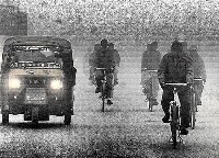
Abstract-Adverse atmospheric conditions such as fog, haze, rain modulate the information carried form a certain point in any scene to the observer such that the colour of landscape and the image contrast are eventually degraded. The resulting image has vague and covered features, thereby hampering the proper functioning of outdoor vision and transport systems. Using region growth method, the sky region is removed and then POSHE is applied on the remaining part of the image. Any blocking effect that might be caused, is removed by using BERF (blocking-effect reduction filter), thereby improving the image quality. This paper also demonstrates that image enhanced by POSHE algorithm has better clarity and definition than enhanced by Histogram Equalization.
Index Terms: POSHE, histogram equalization, BERF, low pass filter, mask, contrast enhancement.
—————————— ——————————
One of the major challenges in image processing, especially in case of backlit images is to enhance the contrast of images. In case of a fog image, concentration of pixel grey levels is observed with the strengthening and weakening of the lower and higher ones grey levels respectively. Hence, the cleanliness of such a fog image demands efficient image contrast enhancement.
Contrast enhancement is acquiring clear image through brightness intensity value redistribution[1]. In other words, that is enhancing features as stretching interval between dark and brightness area. Enhanced image which was result of contrast enhancement processing in preprocessing stage will provide clear image to eyes or assist feature extraction processing in computer vision system.
Image enhancement is majorly classified into two categories: space domain processing and frequency domain processing. Atmospheric physics model under the former category is not always feasible in real time application as it requires the depth of the scene as a complementary information, which can only be obtained with sensor technologies.![]()
Debasmita Hazra is pursuing final year of Electronics & Communication Engineeering at Vellore Institute of Technology, Vellore, India, E- mail:dhazra91@gmail.com
Nekhil Baid is pursuing final year of Electronics & Communication Engineeering at Vellore Institute of Technology, Vellore, India, E- mail:nekhil@gmail.com
hrshtapal @mail.com
Hence, this paper is concentrated on the usage of histogram equalization which comes under the second category.
Here, a novel method called the POSHE algorithm is used to extract fog from the input image.It aims to achieve a non- overlapped sub-block histogram-equalization function, by employing a mask in the form of a low pass filter. This report ensures not only the high contrast associated with local histogram equalization but also the simplicity of global histogram equalization. This low-pass filter-mask eliminates the blocking effect created due to non-overlapped sub-block histogram-equalization. The mask is realized by partially overlapped sub-block histogram-equalization (POSHE). If small blocking effect still generated at the sub-block boundaries, a blocking-effect reduction filter is activated. Since the proposed method involves much less overlapped sub-blocks , it aims at reducing the computation overhead by a factor of about 100 compared to that of local histogram equalization while still achieving high contrast.
The paper analyzes the results obtained by applying regular histogram equalization and POSHE algorithm on a fog image and then compares the result. The proposed algorithm can be used for commercial purposes that demands high efficiency, such as camcorders, closed-circuit cameras, etc.
IJSER © 2013 http://www.ijser.org
International Journal of Scientific & Engineering Research, Volume 4, Issue 4, April-2013 429
ISSN 2229-5518
In order to reduce the calculation complexity, the sky region is separated first. This is done by determining a certain grey threshold value for the sky region and any region that is within the purview of this threshold is removed.
The histogram of image can be seen as a region in the plane. Due to the light scattered by fog, the image of the sky region has higher gray value, thereby presenting a more prominent peak. The appropriate threshold to separate the image is determined by analyzing the concavo-convex distributing of histogram. The convex hull and its maximum convex deficiency are calculated Since the maximum convex deficiency mostly appears in the shoulder of the histogram peak, the gray value of maximum convex deficiency is used as a threshold, T to split the image.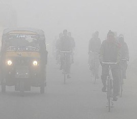
Fig 1:Original Image
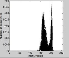
Fig 2:Histogram of the original Image
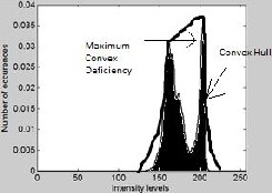
Fig 3:Convex Hull & Maximum Convex Deficiency
Region growth is a method to gather the pixels in the image under observation. It can also be defined as the method based on the clustering of neighboring pixels of a region that verify specific assumptions or conditions. The ultimate aim is to form a group of pixels and take them as seeds, and then use the similarity of the pixels to add the contiguous to the seed. This way the seed grows and expands around in compliance with some predefined rules until the pixels ,in accordance with the rules do no longer exist. The growth stops when the region is non-continuous according to the connectivity of sky region. Thus, the formed region is the result of separation.
A threshold is selected at the initial state to provide edges without taking into consideration the noise in the image. Since the sky region often appears in the top of the image, and considering the possible guarding objects, before selecting the seed ,the location will be decided necessarily.
Region growth has the following properties:
The arrangement of the initial seeds affects the output's quality
The pixel clustering order affects the output
The region growth technique is comparatively simple and the algorithm is comparatively fast.
Histogram equalization is a contrast enhancement technique whereby pixel intensities are adjusted in order to obtain a new enhanced image with increased local contrast. Thus, the intensities can be better distributed on the histogram. Several varieties of different non-adaptive and adaptive techniques exist
for histogram equalization[2].
IJSER © 2013 http://www.ijser.org
International Journal of Scientific & Engineering Research, Volume 4, Issue 4, April-2013 430
ISSN 2229-5518
Contrast enhancement includes both contrast stretching and non-linear contrast enhancements such as histogram equalization[3]. In local (or adaptive) contrast enhancement a sliding m x n window (or sub-block) is repeatedly considered. For each position that the sliding window passes through the contrast enhancement procedure is performed based on the window content, a new grey level being assigned to the central pixel. Since in local contrast enhancement, the transformation for each pixel is obtained from almost overlapped neighbouring sub blocks ,the shape difference of the transformation functions are very small and blocking effects can be ignored. In this case, the difference in contrast enhancement between objects and background can be omitted. The disadvantage of local contrast enhancement is its significant computational overhead.
In POSHE, a sliding window moves from the left side to the right side of the image horizontally in steps (typically a step might be ½, ¼, 1/8 of sub-block width). After window reaches the right side, it returns to the left side and moves down a step. The process is repeated until the sliding window reaches the right-bottom corner of the image[5].
In Figure 1, A, B, C and D are 4 sub-blocks and represent the positions of the sliding window at different stages. The window at B has moved on from A by 1/4 of a sub-block in horizontal direction. Besides horizontal differences, D has been moved 1/4 of a sub-block in the vertical direction. Adding together all of the sub-block contrast enhanced images will form a grid image because of blocking effects. The size of a grid is equal to 1/4 sub-block width by ¼ sub-block height. Unlike conventional adaptive contrast enhancement, in POSHE, the histogram equalisation is performed over the whole sliding widow, and the results accumulated in the output image array.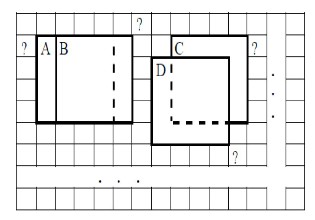
Fig 4: Process depicting the POSHE Algorithm
By employing the weighted sum of neighboring sub- blocks’ histograms ,the transformation function for the current sub-block can be generated in order to reduce the shape difference in non-overlapped sub-block histogram equalization[5]. Here, from the masked histogram of itself and its eight neighboring sub-blocks, the central sub- block’s transformation function is obtained. The mask resembles a low-pass image filter (LPF), and operates is in a way similar to that of an LPF. Image LPF reduces the difference in brightness between neighboring pixels, with the result that the resultant image is blurred. This low- pass filtering for sub-block histograms produces neighboring transformation functions that are similar to each other, thereby resulting in a reduction of the blocking effect.
Fig 5:Transformation Function Generated for the given Image
POSHE includes a BERF (blocking-effect reduction filter) to reduce the blocking effects caused by shape differences between contrast enhancement functions of neighbouring sub- blocks. BERF is a kind of lowpass filter and is only applied to the blocked-boundaries. In the input image, adjacent subblocks have similar brightness and the grey levels of neighbouring pixels at the boundaries of the sub-blocks change gradually. After non-overlapped or partially overlapped sub-block contrast enhancement is performed, their brightness values are changed by each transformation function. Since these transformation functions are obtained from each sub-block's histogram, they have shape differences. The shape differences depend on the overlapping extent among sub-blocks. The more sub-blocks overlap, the less the shape differences and blocking effects.
The size of sub-block has an impact on blocking effects; larger sub-blocks generate smaller blocking effects and vice versa.
IJSER © 2013 http://www.ijser.org
International Journal of Scientific & Engineering Research, Volume 4, Issue 4, April-2013 431
ISSN 2229-5518
At the same time, the size of sub-block affects the results of contrast enhancement; smaller sub-blocks achieving stronger contrast than larger sub-blocks. Using a large sub-block for adaptive contrast enhancement might make the processed image blur even though the blocking effects might almost be negligible, while small sub-block might sharpen the image but generate strong blocking effects.
It is observed that the blocking effects can be decreased by increasing the mask size, at the cost of increased computation complexity. For mask sizes larger than 15X 15, blocking effects are undetectable with simple filtering and performance is compatible with that of block-overlapped histogram equalization.
The basic BERF procedure is as follows.
(1) Sub-block boundaries are checked for blocking effect. To exclude the original object edge on each sub-block boundary, the original edge information at sub-block boundaries must be checked as well. That is,if there exists some level of discontinuity at sub- block boundaries in the POSHE processed image but not in the original image, a blocking effect is generated.
(2) When a blocking effect is detected, filtering starts from each sub-block boundary. An average of the two adjacent boundary pixels is calculated and the brightness values of these two pixels are replaced by this average.
(3) In a perpendicular direction to the boundary, pixel values in an increasing/decreasing
order are replaced by slowly changing values. This replacement value starts from the average, increases by predetermined step size for the brighter sub-block, and
decreases for the darker sub-block. This
filtering ceases when the termination condition is met.
The increasing/decreasing brightness step size is selected so that the human eyes cannot differentiate the discontinuity in brightness at the sub-block boundaries. This unrecognizable brightness level is known to be about 3-4 levels in 8 bit grey- level image6. These procedures are repeated for all sub-block boundaries.
(1) Assuming that the image size is M × N, and the
threshold determined in section 2 is T, starting from the pixel (x0, y0) at left corner of the image, in accordance with the sequence from left to right, top to bottom, find the first pixel (the seed) which gray value is greater than T, and set Flag(x0, y0) = 1;
(2) Judge if the gray value of (xi, yj) is greater than T or not, where (xi, yj) is the neighborhood pixel around the seed;
(3) If it is true, then Flag(xi, yj) = 1, or Flag(xi, yj) = 0; (4) Mark the determined pixels, Mark(xi, yj) = 1;
(5) In the condition of Mark(xi, yj) = 0, determine the neighborhood pixel (xi, yj) of all the pixels with Flag
= 1, and execute (2), (3), (4) circularly, until no more pixels can grow so far.
(1) Let us consider an image m with size a*b.
(2) Determine the number of different intensities present nk, where k is the intensity values of the image ranging from k=0,1,2,….255.
(3) Find the total number of intensities n by adding all the nk values.
(4) The probability of each intensity k, given by pk is then calculated by pk =nk /n.
(5) The cumulative distribution function cdf of pk is then calculated.
(6) After the above steps are done, the mapping function s can be calculated using s=cdf*(l-1) where l is the
number of gray levels.
(7) After calculating the mapping function, the original image is mapped with the new values from the mapping function to give g.
(1) The output image g is initialized to zero, and set the number of computing count as well as the cycle variables i, j as zero;
(2) Determine whether (i, j) belong to the sky region, if
so, then the pixel will be unchanged, if not, then enter step (3);
(3) Set (i, j) as the vertex, from the input image f the corresponding sub-block fB was taken out;
(4) Do the histogram equalization of the sub-block fB, and add the result to the output image, and record the number of operation of each pixel
gB = gB + THE(fB), count(x, y) = count(x, y) + 1 (5) where x, y is the coordinates of pixel;
(6) If j < N -n, move the sub-block horizontally by the step hstep, namely:
(7) set j = j + hstep, repeat Step (4); Otherwise, enter the next step;
(8)If i < M -m, move the sub-block vertically by the step vstep, namely: set i = i + vstep, repeat steps (4); Otherwise, enter the next step;
IJSER © 2013 http://www.ijser.org
International Journal of Scientific & Engineering Research, Volume 4, Issue 4, April-2013 432
ISSN 2229-5518
(9).After the above steps are completed, the gray value of each pixel of the output image divided by the number of computing, the output image g(x, y) = g(x, y) / count(x, y)
(1) Determine whether the blocking effect on the point at the border of the sub-block exists.
(2) When the blocking effect is detected, the smoothing filter is used starting from the border of sub-block.
Fig 6(a)
Fig 6(b)
Fig 6: (a) Histogram Equalization on Unfiltered Image
(b) Histogram Equalization on Filtered Image
Fig 7:Normalized Histogram Equalization of the image changed by the transformation function
Fig 8(a)
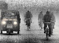
Fig 8(b)
Fig 8: (a) POSHE on Unfiltered Image before using BERF (b) POSHE on Filtered Image before using BERF
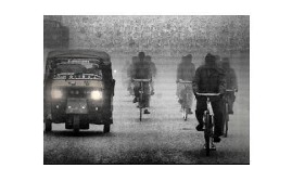
Fig 9(a)
Fig 9(b)
Fig 9: (a) POSHE on Unfiltered Image after using BERF (b) POSHE on Filtered Image after using BERF
IJSER © 2013 http://www.ijser.org
International Journal of Scientific & Engineering Research, Volume 4, Issue 4, April-2013 433
ISSN 2229-5518
The image is analyzed by both the regular Histogram Equalization technique and POSHE Algorithm by using the functions and instructions of MATLAB. It is observed that the image enhanced by POSHE has better clarity and definition and that BERF removes any additional blocking effect that might be caused during the implementation of POSHE. This algorithm with the help of image enhancement techniques can give high definition images.
[1] Kim Tae Keun, Paik Joon Ki, Kang Bong Soon. “Contrast enhancement system using spatially adaptive histogram equalization with temporal filtering”, IEEE Transactions on Consumer Electronics,
1998, 44 (1) ,pp. 82-86.
[2] J. B. Zimmerman, S. M. Pizer, “An evaluation of the effectiveness of adaptive histogram equalization for contrast enhancement”, IEEE ransactions on Medical Imaging, 1988, 7(4), pp. 304-312
[3] J. A .Stark, W. J. Fitzgeralid, “An Altenrative Algorithm for Adaptive
Histogram Equalization”, Graphical Models and Image Processing,
1996, 58 (2), pp. 180-185
[4] Image Segmentation Based On Genetic Algorithm for Region Growth and Region Merging Angelina.S', L.Padma Suresh2, .H.Krishna Veni3 IpG Student, EEE Department, NICHE. ;2Professor, EEE department, NICHE, Kumaracoil;3Professor, IT Department, NICHE, Kumaracoil.
[5] Joung-Youn Kim, Lee-Sup Kim, Seung-Ho Hwang, “An Advanced
Contrast Enhancement Using Partially Overlapped Sub-Block
Histogram Equalization”, IEEE Transactionson Circuits and Systems for Video Technology
IJSER © 2013 http://www.ijser.org