International Journal of Scientific & Engineering Research Volume 2, Issue 4, April-2011 1
ISSN 2229-5518
Improvement of Power System Stability by
Simultaneous AC-DC Power Transmission
T.Vijay Muni, T.Vinoditha, D.Kumar Swamy
Abstract— This paper presents the concept of simultaneous ac-dc power transmission.Long extra high voltage (EHV) ac lines cannot be loaded to their thermal limits due to this instability occurs in the power system.W ith the scheme proposed in this paper,it is possible to load these lines very close to their thermal limits.The conductors are allowed to carry usual ac along dc superimposed on it.The advantage of parallel ac-dc transmission for improvement of transient stability and dynamic stability and dampout oscillations have been established.Simulation study is carried out in MATLAB software package.The results shows the stability of power system when compared with only ac transmission.
Index Terms— — Extra high voltage (EHV) transmission, flexiable ac transmission system (FACTS), HVDC, MATLab, simultaneous ac-dc transmission, Power System Stability, Transmission Efficeincy
1 INTRODUCTION
— — — — — — — — — — • — — — — — — — — — —
VDC transmission lines in parallel with EHV ac lines are recommended to improve transient and dynamic stability as well as to damp out oscilla-
tions in power system. Long EHV ac lines can not be loaded to its thermal limit to keep sufficient margin against transient instability. But for optimum use of transmission lines here is a need to load EHV ac lines close to their thermal limits by using flexible ac trans- mission system (FACTS) components .Very fast control of SCRs in FACTS devices like state VAR system (SVS), controlled series capacitor (CSC), static phase shiftier (SPS) and controlled braking resistors oscillations as well as to control the voltage profile of the line by con- trolling the total reactive power flow. Only the basic idea is proposed along with the feasibility study using elementary laboratory model. The main object is to emphasize the possibility of simultaneous ac-dc transmission with its inherent advantage of power flow control improves stability and damps out oscilla- tions in power system.
EHV ac line may be loaded to a very high val- ue if the conductors are allowed to carry superimposed dc current along with ac current. The added dc power flow does not cause any transient instability.
————————————————
T.Vijay Muni received Masters Degree in Power & Industrial Drives from JNT University, Kakinada, India in 2010.Presently he working as Assis- tant Professor in Electrical and Electronics Department,Sri Sarathi Insti- tute of Engineering & Technology, Nuzvid,India.PH-09000055144.
E-mail: www.vijaymuni@gmail.com
T.Vinoditha is currently pursuing master’s degree program in Electrical
Power Systems in JNT University, Hyderabad, India. PH-09052352600. E-mail: tadanki_vinoditha@yahoo.com
D.Kumar Swamy recwived Masters Degree in EPSHV from JNT Universi- ty, Kakinada, India .Presently he working as Associate Professor & Head in Electrical & Electronics Engineering Department,Dr.Paul Raj Engineering College,Bhadrachalem, India.PH-09866653638.
E-mail: dkswamy@yahoo.co.in
This paper presents a simple scheme of simul- taneous EHV ac-dc power flow through the same transmission line with an object to achieve the advan- tages of parallel ac-dc transmission. Simultaneous ac- dc transmission may also claim advantages in some specific applications LV (low voltage) and MV (Me- dium voltage) system.
The flexible ac transmission system (FACTS) con- cepts, based on applying state-of-the-art power elec- tronic technology to existing ac transmission system, improve stability to achieve power transmission close to its thermal limit. Another way to achieve the same goal is simultaneous ac–dc power transmission in which the conductors are allowed to carry superim- posed dc current along with ac current. Ac and dc power flow independently, and the added dc power flow does not cause any transient instability.
2 COCEPT OF SIMULTANEOUS AC-DC
TRANSMISSION
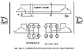
The circuit diagram in Figure1 shows the basic scheme for simultaneous ac-dc transmission. The dc power is obtained through the rectifier bridge and in-
IJSER © 2011 http://www.ijser.org
International Journal of Scientific & Engineering Research Volume 2, Issue 4, April-2011 2
ISSN 2229-5518
jected to the neutral point of the zigzag connected sec- ondary of sending end transformer, and again it is re- converted to ac by the inverter bridge at the receiving end. The inverter bridge is again connected to the neu- tral of zigzag connected winding of the receiving end transformer. Star connected primary windings in place of delta-connected windings for the transformers may also be used for higher supply voltage. The single cir- cuit transmission line carriers both 3 –phase ac and dc
er at the sending end is converted into dc by the ter- tiary winding of the transformer connected to rectified
are neglected can be written as
Sending end voltage:
Vs = AVR + BIR (1)
Sending end current:
Is = CVR + DIR (2)
Sending end power:
R)/B* + (D*/B*) Vs2 (3)
Receiving end power:
* V )/B* - (A*/B*)V
(4)
bridge. The same dc power is reconverted to ac at the
received end by the tertiary winding of the receiving
end transformer connected to the inverter bridge.
Each conductor of the line carries one third of the total
dc current along with ac current Ia .The return path of the dc current is through the ground. Zigzag con- nected winding is used at both ends to avoid satura-
tion of transformer due to dc current flow. A high val- ue of reactor, X d is used to reduce harmonics in dc cur- rent.
In the absence of zero sequence and third harmon- ics or its multiple harmonic voltages, under normal operating conditions, the ac current flow will be re- stricted between the zigzag connected windings and the three conductors of the transmission line. Even the presence of these components of voltages may only be able to produce negligible current through the ground due to high of Xd.
Assuming the usual constant current control of rec-
tifier and constant extinction angle control of inverter,
the equivalent circuit of the scheme under normal
steady state operating condition is shown in Fig.2.
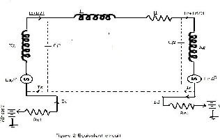
The dotted line in the figure shows the path of ac re- turn current only. The ground carries the full dc cur- rent Id only and each conductor of the line carries Id/3 along with the ac current per phase
The expressions for ac voltage and current and the power equations in terms of A,B,C and D parameters of each line when the resistive drop in transformer winding and in the line conductors due to dc current
PR+jQR = (VS R R2
The expressions for dc current and the dc power, when
the ac resistive drop in the line and transformer are
neglected,
Dc current:
Id = (Vdrcosa - Vdicosy)/(Rer+(R/3) – Rci) (5) Power in inverter:
Pdi = Vdi x Id (6) Power in rectifier:
Pdr = Vdr x Id (7)
Where R is the line resistance per conductor, Rcr and Rci commutating resistances, a andy, firing and extinction angles of rectifier and inverter respectively and Vdr and Vdi are the maximum dc voltages of rectifier and inver- ter side respectively. Values of Vdr and Vdi are 1.35 times line to line tertiary winding ac voltages of re- spective sides.
Reactive powers required by the converters are:
Qdi = Pdi tan8I (8) Qdr = Pdr tan8r (9) Cos8I = (cosy + cos (y + 1-i) )/2 (10) Cos8r = (cosa + cos (a + 1-r) )/2 (11)
Where 1-I and 1-r are commutation angles of inverter and rectifier respectively and total active and reactive powers at the two ends are
Pst = Ps + Pdr and Prt = PR + Pdi (12) Qst = Qs + Qdr and Qrt = QR + Qdi (13)
Total transmission line loss is:
PL = (Ps + Pdr) – (PR + Pdi) (14) Ia being the rms ac current per conductor at any point
of the line, the total rms current per conductor be-
comes:
I = sqrt (Ia2 + (Id/3)2) and PL = 3I2R (15) If the rated conductor current corresponding to its al-
lowable temperature rise is Ith and
Ia = X * Ith; X being less than unity, the dc current be- comes:
Id = 3 x (sqrt (1-x2) ) Ith (16) The total current I in any conductor is asym-
metrical but two natural zero-crossings in each cycle in
IJSER © 2011 http://www.ijser.org
International Journal of Scientific & Engineering Research Volume 2, Issue 4, April-2011 3
ISSN 2229-5518
current wave are obtained for (Id/3Ia) <1.414.
The instantaneous value of each conductor voltage with respect to ground becomes the dc voltage Vd with
a superimposed sinusoidally varying ac voltages hav- ing rms value Eph and the peak value being:
Emax = V + 1.414 Eph
Electric field produced by any conductor vol-
tage possesses a dc component superimposed with
sinusoidally varying ac component. But the instanta-
neous electric field polarity changes its sign twice in
cycle if (Vd/Eph) < 1.414.Therefore, higher creepage distance requirement for insulator discs used for
HVDC lines are not required.
Each conductor is to be insulated for Emax but the line to line voltage has no dc component and
ELL(max) = 2.45 Eph.Therefore, conductor to conductor separation distance is determined only by rated ac vol- tage of the line.
Assuming Vd/Eph = k
Pdc/’Pac = (Vd * Id)/(3 * Eph * Ia * cos8) = (k * sqrt(1- x2))/(x * cos8 ) (17)
Total power
Pt = Pdc + Pac = (1 + [k * sqrt (1-x2)]/(x * cos8)) * Pac (18)
Detailed analysis of short current ac design of protective scheme, filter and instrumentation network required for the proposed scheme is beyond the scope of present work, but preliminary qualitative analysis presented below suggests that commonly used tech- niques in HVDC/ac system may be adopted for this purposes.
In case of fault in the transmission system, gate signals to all the SCRs are blocked that to the bypass SCR s are released to protect rectifier and inverter bridges. CBs are then tripped at both ends to isolate the complete system. As mentioned earlier, if (Id3Ia) <1.414, CBs connected at the two ends of transmission line inter- rupt current at natural current zeroes and no special dc CB is required. To ensure proper operation of trans- mission line CBs tripping signals to these CBs may only be given after sensing the zero crossing of current by zero crossing detectors. Else CB’s connected to the delta side of transformers (not shown in figure1) may be used to isolate the fault. Saturation of transformer core, if any, due to asymmetric fault current reduces line side current but increases primary current of trans- former. Delta side CBs, designed to clear transformers terminal faults and winding faults, clear these faults easily.
Proper values of ac and dc filters as used in HVDC system may be connected to the delta side and zigzag neutral respectively to filter out higher harmon- ics from dc and ac supplies. However, filters may be omitted for low values of Vd and Id.
At neutral terminals of zigzag winding dc cur-
rent and voltages may be measured by adopting com-
mon methods used in HVDC system. Conventional
cvts as used in EHV ac lines are used to measure ac component of transmission line voltage. Superimposed dc voltage in the transmission line does not affect the working of cvts. Linear couplers with high air-gap core may be employed for measurement of ac component of line current as dc component of line current is not able to saturate high air-gap cores.
Electric signal processing circuits may be used to generate composite line voltage and current wave- forms from the signals obtained for dc and ac compo- nents of voltage and current. Those signals are used for protection and control purposes.
3 SELECTION OF TRANSMISSION VOLTAGE
The instantaneous value of each conductor voltage with respect to ground becomes more in case of simul- taneous ac-dc transmission system by the amount of the dc voltage superimposed on ac and more discs are to be added in each string insulator to withstand this increased dc voltage. However, there is no change re- quired in the conductor separation distance, as the line-to-line voltage remains unaltered. Therefore, tower structure does not need any modification if same conductor is used.Another possibility could be that the original ac voltage of the transmission be reduced as dc voltage is added such that peak voltage with re- spect to ground remain unchanged. Therefore, there would be no need to modify the towers and insulator strings.
4 PROPOSED APPLICATIONS
1.Long EHV ac lines can not be loaded to their ther- mal limit to keep sufficient margin against transient instability and to keep voltage regulation within al- lowable limit, the simultaneous power flow does not imposed any extra burden on stability of the system, rather it improves the stability. The resistive drop due to dc current being very small in comparison to im- pedance drop due to ac current, there is also no appre- ciable change in voltage regulation due to superim- posed dc current.
2. Therefore one possible application of simultaneous ac-dc transmission is to load the line close to its ther- mal limit by transmitting additional dc power. Figure3 shows the variation of Pt/Pac for changing values of k and x at unity power factor. However, it is to be noted that additional conductor insulation is to be provided due to insertion of dc.
3. Necessity of additional dc power transmission will be experienced maximum during peak load period which is characterized with lower than rate voltage. If dc power is injected during the peak loading period only with V d being in the range of 5% to 10% of E ph, the same transmission line without having any en- hanced insulation level may be allowed to be used For
IJSER © 2011 http://www.ijser.org
International Journal of Scientific & Engineering Research Volume 2, Issue 4, April-2011 4
ISSN 2229-5518
a value of x=0.7 and V d =0.05 E ph or 0.10 E ph, 5.1% or
10.2% more power may be transmitted.
4.By adding a few more discs in insulator strings of
each phase conductor with appropriate modifications
in cross-arms of towers insulation level between phase
to ground may be increased to a high value, which permits proportional increase in Emax, Therefore high- er value of Vd may be used to increase dc and total power flow through the line. This modification in the
exiting ac lines is justified due to high cost of a sepa- rate HVDC line.
5. With the very fast electronic control of firing angle (a ) and extinction angle (y ) of the converters, the fast control of dc power may also be used to improve dy- namic stability and damping out oscillations in the system similar to that of the ac-dc parallel transmission lines.
6. Control of a and y also controls the rectifier and in- verter VAR requirement and therefore, may be used to control the voltage profile of the transmission line dur- ing low load condition and works as inductive shunt compensation. It may also be considered that the capa- citive VAR of the transmission line is supplying the whole or part of the inductive VAR requirement of the converter system. In pure HVDC system capacitance of transmission line cannot be utilized to compensate inductive VAR.
7. The independent and fast control of active and reac- tive power associated with dc, superimposed with the normal ac active and reactive power may be consi- dered to be working as another component of FACTS.
8. Simultaneous ac-dc power transmission may find its
are used at each end. A supply of 3-phase, 400V, 50Hz are given at the sending end and a 3-phase, 400 V, 50
Hz,1 HP induction motor in addition to a 3-phase,
400V, 0.7 KW resistive load was connected at the re-
ceiving end. A 10 A, 110 Vdc reactor (Xd) was used at
each end with the 230V zigzag connected neutral. Two identical SCR bridges were used for rectifier and inver- ter. The dc voltages of rectifier and inverter bridges were adjusted between 145 V to135 V to vary dc cur-
rent between 0 to 3A.
The same experiment was repeated by replacing the
rectifier at the sending and and the inverter at receiv-
ing end by 24V battery and a 5A, 25 rheostat respec-
tively, between Xd and ground.
The power transmission with and without dc com-
ponent was found to be satisfactory in all the cases. To
check the saturation of zigzag connected transformer
for high value of Id, ac loads were disconnected and dc current was increased to 1.2 times the rated current for a short time with the input transformer kept energized
from 400V ac. But no changes in exciting current and terminal voltage of transformer were noticed verifying no saturation even with high value of I d.
6 SIMULATION RESULTS
The loadability of Moose (commercial name), ACSR, twinbundle conductor, 400-kV, 50-Hz, 450-km double circuit line has been computed.
power upgrading by combining ac dc transmission
application in some special cases of LV and MV distri- bution system.
a3 A+ B+
b3 C+ A-
B-
A+ a3
B+
C+ b3
A-
B-
C- c3
When 3-phase power in addition to dc power is sup- plied to a location very near to a furnace or to a work place having very high ambient temperature, rectifica- tion of 3-phase supply is not possible at that location
c3 C-
Zigzag
Phase-Shi fting T ransformer
500kV, 60 Hz
5000 MVA equivalent
Di stributed Parameters Line
Zigzag
Phase-Shifting T ransformer1
using semiconductor rectifier. In such place simultane- A A A
a A A
b B B
+ i
+ -
Current Measurement Scope
+ A Aa
B Bb
A A A
B B B
ous ac-dc transmission is advantageous.
C C C
c C -
- C Cc
C C C
In air craft 3-phase loads are generally fed with higher frequency supply of about 400Hz and separate line is used for dc loads. Skin effect restricts the optimum use of distribution wires at high frequency. Simultaneous
phi = 80 deg. 3rd harm.
Open this block
Brect
Rectifier
a3 b3
A+ B+
C+ A-
Inverter
A+ B+ C+ A-
B-
Binv
a3 b3
phi = 80 deg. 3rd harm.
ac-dc power transmission reduces both volume and
to visualize
recorded s ignals
B- c3 C-
Zigzag
Distributed Parameters Li ne1
C- c3
Zi gzag
weight of distributors.
9. Another possible application is the transmission of
dc power generated by PV solar cells directly to re-
mote dc loads through 3-phase ac line. In all cases of
separate dc supply filter networks are not required.
Data Acquis ition
AC fi lters
60 Hz
600 Mvar
Phase-Shifting T ransformer2
Rectifier
Control and Protection
Mas ter Control
Mas ter Control
Phase-Shifting T ransformer
AC fil ters
50 Hz
600 Mvar
Discrete, T s = s.
5 EXPERIMENTAL VERIFICATION
The feasibility of the basic scheme of simultaneous ac-dc transmission was verified in the laboratory. Transformer having a rating of 2 kVA, 400/230/110V
Inverter
Control and Protection
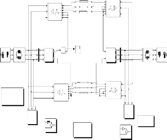
Fig 3: Simulink Model of Simultaneous AC-DC Trans- mission
IJSER © 2011 http://www.ijser.org
International Journal of Scientific & Engineering Research Volume 2, Issue 4, April-2011 5
ISSN 2229-5518
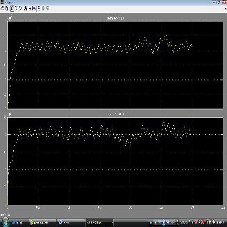
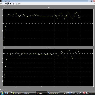
Fig 4 Sending end and receiving end voltages
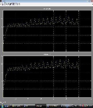
Fig 5: Sending and receiving currents
Fig 6: Combined AC-DC currents
TABLE I
COMPUTED RESULTS
Power Angle | 30 | 45 | 60 | 75 |
AC Current(kA) | 0.416 | 0.612 | 0.80 | 0.98 |
DC Current(kA) | 5.25 | 5.07 | 4.80 | 4.50 |
AC Power(MW) | 290 | 410 | 502 | 560 |
DC Power(MW) | 1685 | 1625 | 1545 | 1150 |
Total Power(MW) | 1970 | 2035 | 2047 | 1710 |
TABLE II
SIMULATION RESULTS
Power Angle | 30 | 45 | 60 | 75 |
PS (MW) | 2306 | 2370 | 2380 | 2342 |
Pac (MW) | 295 | 410 | 495 | 540 |
Pdc (MW) | 1715 | 1657 | 1585 | 1498 |
Pac loss (MW) | 12 | 30 | 54 | 82 |
Pdc loss (MW) | 280 | 265 | 241 | 217 |
PR (MW) | 1988 | 2050 | 2060 | 1995 |
7 CONCLUSION
A simple scheme of simultaneous EHV ac-dc power transmission through the same transmission line has been presented. Expressions of active and reactive powers associated with ac and dc, conductor voltage level and total power have been obtained for
IJSER © 2011 http://www.ijser.org
International Journal of Scientific & Engineering Research Volume 2, Issue 4, April-2011 6
ISSN 2229-5518
steady state normal operating condition. The possible applications of the proposed scheme may be listed as: loading a line close to its thermal limit, improvement of transient and dynamic stability and damping of os- cillations. In LV and MV distribution system the pro- posed scheme may be applied in a workplace having high ambient temperature or fed with high frequency supply or with PV solar cells. Only the basic scheme has been presented with qualitative assessment for its implementation. Details of practical adaptation are beyond the scope of the present work.
ACKNOWLEDGMENT
We are thankful to Department of Electrical and Electonics Engineering of Sri Sarathi Institute of Engineering and Technology, Nuzvid, India & Dr.Paul Raj Engineering College, Bhadrachalem, India with whom we had useful discussions regarding HVDC, Performance of transmissions lines. Any suggestions for further improvement of this topic are most wel- come
REFERENCES
[1] N. G. Hingorani, “FACTS—flexible A.C. transmission system,” in Proc. Inst. Elect. Eng. 5th. Int. Conf. A.C. D.C. Power Trans- mission,
[2] Padiyar.’HVDC Power Transmission System.’ Wiley East- ern, New Delhi, 1993)
[3] H. Rahman and B H Khan “Stability Improvement of Power
Systemby Simultaneous AC-DC Power Transmission” Electric Power System Research Journal, Elsevier, Paper Editorial ID No. EPSRD- 06-00732, Press Article No. EPSR-2560— Digital Object.
[4] I W Kimbark.’Direct Current Transmission Vol-I.’Wiley,
New York, 1971.
IJSER © 2011 http://www.ijser.org