The research paper published by IJSER journal is about Improvement of System Reliability & Power Transfer Capability using Distributed Power- Flow Controller 1
ISSN 2229-5518
Improvement of System Reliability & Power Transfer Capability using Distributed
Power- Flow Controller (DPFC)
P.RAMESH1, Dr.M.DAMODARA REDDY2
1Research Scholar, Department of Electrical and Electronics Engineering, SVU College of Engineering, S V University, Tirupati, A.P., India.
2Associate Professor, Department of Electrical and Electronics Engineering, SVU College of Engineering, S V University,
Tirupati, A.P., India.
E-mail: pramesheee@yahoo.co.in,mdreddy999@rediffmail.com
Abstract---The present paper describes the modeling of Distributed Power Flow Controllers (DPFC) for studying the steady-state response and behavior of Transmission networks equipped with FACTS devices. Detailed simulations are carried out on two- machine systems to illustrate the control features of these devices and their influence to increase power transfer capability and improve system Reliability. The DPFC is derived from the unified power-flow controller (UPFC) and DPFC has the same control capability as the UPFC. The DPFC can be considered as a UPFC with an eliminated common dc link. The active power exchange between the shunt and series converters, which is through the common dc link in the UPFC, is now through the transmission lines at the third-harmonic frequency. As the D-FACTS converters are single-phase and floating with respect to the ground, there is no high-voltage isolation required between the phases. The interaction between the DPFC, the network and the machines are analyzed.
Index Terms—FACTS,DPFC, device modeling, power transmission AC–DC power conversion, power semiconductor
devices, power system control, power - transmission control.
1. INTRODUCTION
—————————— ——————————
Synchronous series compensator (SSSC) [2] is a series
Now-a-days in power systems, there is a great desire of a fast and reliable control of the power flow controller because of the growing demand of energy, the aging of networks flow and distributed generations [1] .The flexible ac transmission system (FACTS) technology is the application of power electronics in transmission systems [1]. The main purpose of this technology is to control and regulate the electric variables in the power systems.
This is achieved by using converters as a controllable
interface between two power system terminals. The resulting converter representations can be useful for a variety of configurations. Basically, the family of FACTS devices based on voltage source converters (VSCs) consists of a series compensator, a shunt compensator, and a shunt/series compensator. The static Compensator (STATCOM) [2] is a shunt connected device that is able to provide reactive power support at a network location far away from the generators. Through this reactive power injection, the STATCOM can regulate the voltage at the connection node. The static
device which injects a voltage in series with the transmission line. Ideally, this injected voltage is in quadrature with the line current, such that the SSSC behaves like an inductor or a capacitor for the purpose of increasing or decreasing the overall reactive voltage drop across the line, and thereby, controlling the transmitted power. In this operating mode, the SSSC does not interchange any real power with the system in steady- state. The unified power-flow controller (UPFC) [2] is the most versatile device of the family of FACTS devices, since it is able to control the active and the reactive power, respectively, as well as the voltage at the connection node.
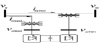
Fig.1 Schematic representation of the UPFC
IJSER © 2012
http://www.ijser.org
The research paper published by IJSER journal is about Improvement of System Reliability & Power Transfer Capability using Distributed Power- Flow Controller 2
ISSN 2229-5518
The Unified Power Flow Controller (UPFC) is comprised of a STATCOM and a SSSC [3], coupled via a common DC link to allow bi-directional flow of active power between the series output terminals of the SSSC and the shunt output terminals of the STATCOM [4].Each converter can independently generate (or) absorb reactive power at its own AC terminal. The two converters are operated from a DC link provided by a DC storage capacitor. The configuration of a UPFC is shown in Fig 1.
The UPFC is not widely applied in practice, due to their high cost and the susceptibility to failures. Generally, the reliability can be improved by reducing the number of components; however, this is not possible due to the complex topology of the UPFC. To reduce the failure rate of the components, selecting components with higher ratings than necessary or employing redundancy at the component or system levels. Unfortunately, these solutions increase the initial investment necessary, negating any cost related advantages. Accordingly, new approaches are needed in order to increase reliability and reduce cost of the UPFC.
After studying the failure mode of the combined FACTS devices, it is found that a common DC link between converters reduces the reliability of a device, because a failure in one converter will pervade the whole device through the DC link. By eliminating this DC link, the converters within the FACTS devices are operated independently, thereby increasing their reliability.
The same as the UPFC, the DPFC is able to
control all system parameters like line impedance, transmission angle & bus voltage. The DPFC eliminates the common dc link between the shunt and series converters. The active power exchange between the shunt and the series converter is through the transmission line at the third-harmonic frequency. The series converter of the DPFC employs the distributed FACTS (D-FACTS) concept [5]. Comparing with the UPFC, the DPFC have two major advantages: 1) low cost because of the low-voltage isolation and the low component rating of the series converter and 2) High reliability because of the redundancy of the series converters and high control capability. DPFC can also be used to improve the power quality and system stability
such as power oscillation damping [6], Voltage sag restoration or balancing asymmetry.
II. DPFC Topology
The flow chart for DPFC is shown in fig.2. Similar as the UPFC, the DPFC consists of shunt and series connected converters. The shunt converter is similar as a STATCOM, while the series converter employs the Distributed Static series compensator (DSSC) concept, which is to use multiple single-phase converters instead of one three-phase converter. Each converter within the DPFC is independent and has its own DC capacitor to provide the required DC voltage. The configuration of the DPFC is shown in Figure 3.
As shown, besides the key components- shunt
and series converters, a DPFC also requires a high pass filter that is shunt connected to the other side of the transmission line and a Y- Δ transformer on each side of the line. The reason for these extra components will be explained later.
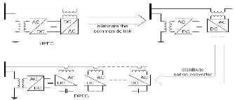
Fig. 2 Flowchart from UPFC to DPFC.
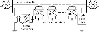
Fig. 3 DPFC configuration.
III. DPFC Operating Principle
1. Active power exchange with eliminated DC link:
Within the DPFC, the transmission line presents a common connection between the AC ports of the shunt and the series converters. Therefore, it is possible to exchange active power through the AC ports. The method is based on power theory of non-sinusoidal
components. According to the Fourier analysis, non-
IJSER © 2012
http://www.ijser.org
The research paper published by IJSER journal is about Improvement of System Reliability & Power Transfer Capability using Distributed Power- Flow Controller 3
ISSN 2229-5518
sinusoidal voltage and current can be expressed as the sum of sinusoidal functions in different frequencies with different amplitudes. The active power resulting from this non-sinusoidal voltage and current is defined as the mean value of the product of voltage and current. Since the integrals of all the cross product of terms with different frequencies are zero, the active power can be expressed by:
P Vi Ii cos i ………… (1)
i 1
Where Vi and Ii are the voltage and current at the ith
Fig. 4 Active power exchange between DPFC
converters.
The high-pass filter within the DPFC blocks the fundamental frequency components and allows the harmonic components to pass, thereby providing a return path for the harmonic components. The shunt and series converters, the high pass filter and the ground form a closed loop for the harmonic current.
2. Using third harmonic components
Due to the unique features of 3rd harmonic frequency components in a three phase system, the 3rd harmonic is
selected for active power exchange in the DPFC. In a
harmonic frequency respectively, and i
is the
three-phase system, the 3rd harmonic in each phase is
corresponding angle between the voltage and current.
Equation (1) shows that the active powers at different frequencies are independent from each other and the voltage or current at one frequency has no influence on the active power at other frequencies. The independence of the active power at different frequencies gives the possibility that a converter without a power source can generate active power at one frequency and absorb this power from other frequencies.
By applying this method to the DPFC, the shunt converter can absorb active power from the grid at the fundamental frequency and inject the power back at a harmonic frequency. This harmonic active power flows through a transmission line equipped with series converters. According to the amount of required active power at the fundamental frequency, the DPFC series converters generate a voltage at the harmonic frequency, thereby absorbing the active power from harmonic components.
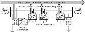
Neglecting losses, the active power generated at the fundamental frequency is equal to the power absorbed at the harmonic frequency. For a better understanding, Fig 4. indicates how the active power is exchanged between the shunt and the series converters in the DPFC system.
identical, which means they are ‗zero-sequence‘ components. Because the zero-sequence harmonic can be naturally blocked by Y- Δ transformers and these are widely incorporated in power systems (as a means of changing voltage), there is no extra filter required to prevent harmonic leakage.
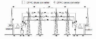
Fig.5 3rd Harmonic Current flow in DPFC
As introduced above, a high-pass filter is required to make a closed loop for the harmonic current and the cutoff frequency of this filter is approximately the fundamental frequency. Because the voltage isolation is high and the harmonic frequency is close to the cutoff frequency, the filter will be costly. By using the zero- sequence harmonic, the costly filter can be replaced by a cable that connects the neutral point of the Y- Δ transformer on the right side in Fig 6. with the ground. Because the Δ -winding appears open-circuit to the 3rd harmonic current, all harmonic current will flow through the Y-winding and concentrate to the grounding cable as
shown in Fig 5.
IJSER © 2012
http://www.ijser.org
The research paper published by IJSER journal is about Improvement of System Reliability & Power Transfer Capability using Distributed Power- Flow Controller 4
ISSN 2229-5518
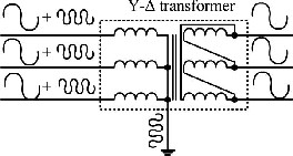
Fig. 6 Utilize grounded Y- Δ transformer to filter zero- sequence harmonic.
The harmonic at the frequencies like 3rd, 6th, 9th... are
all zero-sequence and all can be used to exchange active power in the DPFC. However, the 3rd harmonic is selected, because it is the lowest frequency among all zero-sequence harmonics.
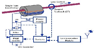
IV. Distributed Series Converter
This paper introduces the concept of a Distributed Static Series Compensator (DSSC) which is shown in fig. 7. That uses multiple low-power single- phase inverters that attach to the transmission conductor and dynamically control the impedance of the transmission line, allowing control of active power flow on the line [4]. The DSSC inverters are self-powered by induction from the line itself, float electrically on the transmission conductors, and are controlled using wireless or power line communication techniques. Implementation of system level control uses a large number of DSSC modules controlled as a group to realize active control of power flow.
The DSSC can be used to either increase or decrease the effective line impedance, allowing current to be ‗pushed‘ away from or ‗pulled‘ into a transmission line. The DSSC concept overcomes some of the most serious limitations of FACTS devices, and points the way to a new approach for achieving power flow control—the use of Distributed FACTS or D-FACTS devices.
Fig. 7 DSSC Circuit schematic [7]
V. DPFC Control
To control multiple converters[8], a DPFC consists of three types of controllers: central control, shunt control and series control, as shown in Figure 8.
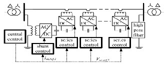
Fig. 8 DPFC control block diagram.
A. Central Control
The central control generates the reference signals for both the shunt and series converters of the DPFC. It is focused on the DPFC tasks at the power-system level, such as power-flow control, low-frequency power oscillation damping, and balancing of asymmetrical components. According to the system requirement, the central control gives corresponding voltage reference signals for the series converters and reactive current signal for the shunt converter. All the reference signals generated by the central control are at the fundamental frequency.
B. Series Control
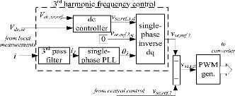
Each DPFC series converter is locally controlled by its own controller, and the scheme for each series control is identical. To control the series converter, separate control loops are employed for the two frequency components. The 3rd harmonic control loop is used for DC voltage control. The block diagram of the
DPFC series converter control is shown in fig. 9.
IJSER © 2012
http://www.ijser.org
The research paper published by IJSER journal is about Improvement of System Reliability & Power Transfer Capability using Distributed Power- Flow Controller 5
ISSN 2229-5518
transmission line have no loss, the total active power generated by the two voltage sources will be zero. The multiple series converters are simplified as one large converter with a voltage that is equal to the voltages of all series converters. Consequently, a simplified
representation of the DPFC is shown in Fig 11.[13]
Fig.9. Block diagram of the series converter control [9].
C. Shunt Control
The shunt converter contains two converters. The single- phase converter injects the constant 3rd harmonic current into the grid. The three-phase converter maintains the DC voltage at a constant value and generates reactive power to the grid. The control of each converter is independent. A block diagram of the shunt converter control is shown in Fig 10.
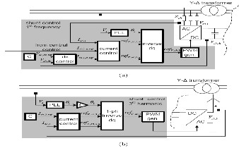
Fig. 10 Control scheme of the shunt converter[10] (a)for the fundamental frequency components; (b) for the 3rd harmonic frequency components
VI. DPFC Steady-State Analysis
In this section, the steady-state behavior of the DPFC is analyzed and the control capability of the DPFC is expressed in the parameters of both the network and DPFC itself[11]
DPFC Simplification and Equivalent Circuit
To simplify the DPFC, the converters are replaced by controllable voltage sources in series with impedance.[12] Since each converter generates voltages at two different frequencies, they are represented by two
series connected controllable voltage sources, one at the
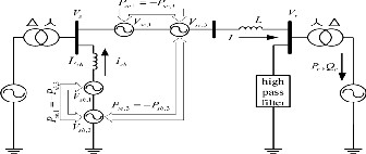
Fig. 11 DPFC simplified representation.
This representation consists of both the fundamental frequency and 3rd harmonic frequency components. For an easier analysis, based on the superposition theorem, the circuit in Fig 11. Can be further simplified by splitting it into two circuits at different frequencies. The two circuits are isolated from each other, and the link between these circuits is the active power balance of each converter, as shown in Fig 12.
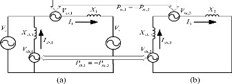
Fig. 12 DPFC equivalent circuit: (a) the fundamental frequency; (b) the 3rd harmonic Frequency
VII. Power flow control capability
The power flow control capability of the DPFC can be illustrated by the active power Pr and reactive power Qr at the receiving end, shown in Figure 12(a). With reference to this figure, the active and reactive power flow can be expressed as follows:
P jQ V I *
V V V

r
fundamental frequency and the other at the 3rd harmonic
where the phasor valujXes1
are used for voltages and
frequency. Assuming the converters and the
currents, * means the conjugate of a complex number
IJSER © 2012
http://www.ijser.org
The research paper published by IJSER journal is about Improvement of System Reliability & Power Transfer Capability using Distributed Power- Flow Controller 6
ISSN 2229-5518
and X1 = ωL is the line impedance at the fundamental frequency. The power flow (Pr,Qr) consists of two parts: the power flow without DPFC compensation (Pr0,Qr0) and the part that is varied by the DPFC (Pr,c,Qr,c). The power flow without DPFC compensation (Pr0,Qr0) is given by:[13]
*
Vs Vr

Pr 0 jQr 0 Vr
jX1
………. (3)
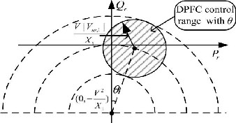
Fig. 13 DPFC active and reactive power control range
Accordingly, by substituting (3) into (2), the DPFC
control range on the power flow can be expressed as:
with the transmission angle θ.
P jQ
*
V Vse

r ,c r ,c r
jX1
…….. (4)
As the voltage at the receiving end and the line impedance are fixed, the power flow control range of the
DPFC is proportional to the maximum voltage of the
series converter. Because the voltage
*
se,1
can be
rotated 360◦, the control range of the DPFC is a circle in the complex PQ-plane, whose center is the uncompensated power flow (Pr0,Qr0) and whose radius is equal to |Vr||Vse,1|/X1. By assuming that the voltage magnitude at the sending and receiving ends are both V, the control capability of the DPFC is given by the
following formula
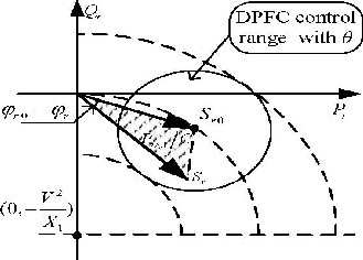
Fig. 14 Relationship between Pse,1 and the power flow at the receiving end
(P P
)2 (Q Q

2
V V
)2 se,1
r r 0
r r 0
X1
...(5)
In the complex PQ-plane, the locus of the power flow without the DPFC compensation f(Pr0,Qr0) is a


2
circle with radius V
/ X1
around its center (defined by


2
coordinates P = 0 and Q = V
/ X1 ). Each point of this
circle gives Pr0 and Qr0 values of the uncompensated system[13] at the corresponding transmission angle θ. The boundary of the attainable control range for Pr and Qr is obtained from a complete rotation of the voltage Vse,1 with its maximum magnitude. Figure 13 shows the power flow control range of the DPFC with the
transmission angle θ.[13]
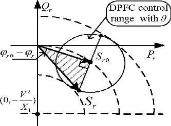
Fig.15 Maximum active power requirement of the series converters.
IJSER © 2012
http://www.ijser.org
The research paper published by IJSER journal is about Improvement of System Reliability & Power Transfer Capability using Distributed Power- Flow Controller 7
ISSN 2229-5518
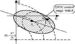
Fig. 16 DPFC power-flow control range.
VIII. Simulation Results
To simulate the effect of the DPFC on Distributed system is processed using MATLAB. One shunt converter and two single phase series converters are built and tested. The specifications of the DPFC in MATLAB are listed below.
Parameter | Value |
Sending end voltage (Vs) | 200 V |
Receiving end voltage (Vr) | 200 V |
Series converter voltage (Vse) | 120 V |
Shunt converter voltage (Vsh) | 120 V |
Line Resistance (r) | 0.3864 Ω/km |
Line inductance (L) | 4.1264 mH/km |
Source resistance (rs) | 0.8929 Ω |
Source Inductance (Ls) | 16.58 mH |
Series capacitor (Cse) | 1 μF |
Shunt capacitor (Csh ) | 1 μF |
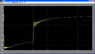
Fig.17Voltage across the Capacitor of shunt converter
Fig.17 Consists of the DC voltage has a small oscillation, however does not influence the DPFC
control.
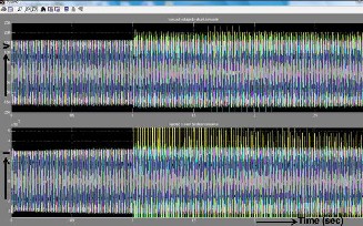
Fig.18 Injected voltage and current injected by shunt converter
Fig.18 contains two frequency components
ie.,fundamental and Third harmonic frequency components. The constant 3rd harmonic current injected by the shunt converter is evenly dispersed to the 3 phases and is superimposed on the fundamental voltage and current.
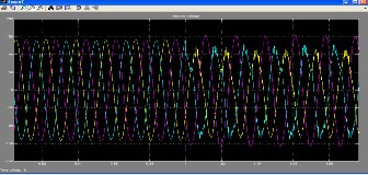
Fig.19 Injected Voltage by Series Converter
Fig.19 contains two frequency components i.e., fundamental and Third harmonic frequency components as shown in Fig.4. The constant 3rd harmonic voltage injected by the series converter is evenly dispersed to the
3 phases and is superimposed on the fundamental voltage.
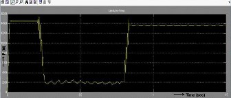
Fig.20: Line active power for without DPFC
IJSER © 2012
http://www.ijser.org
The research paper published by IJSER journal is about Improvement of System Reliability & Power Transfer Capability using Distributed Power- Flow Controller 8
ISSN 2229-5518
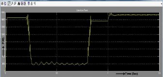
Fig.21: Line active power for with DPFC
Fig.20 and 21 illustrates the line active power of transmission system without and with DPFC. The series converters are able to absorb and inject active power in the line at the fundamental frequency.
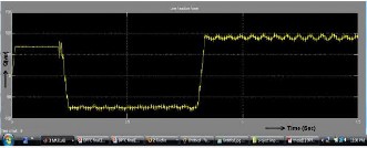
Fig.22: Line reactive power for without DPFC
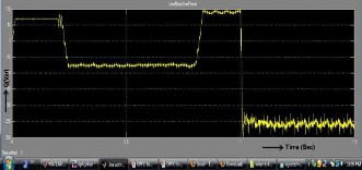
Fig.23: Line reactive power for with DPFC
Fig.22 and 23 illustrates the line reactive power for without and with DPFC.The series converters are able to absorb and inject reactive power in the line at the fundamental frequency and increase the active power flow in the system.
IX. CONCLUSION
The DPFC emerges from the UPFC and inherits the control capability of the UPFC, which is the simultaneous adjustment of the line impedance, the transmission angle, and the bus-voltage magnitude. The common dc link between the shunt and series converters, which is used for exchanging active power in the UPFC, is eliminated. This power is now transmitted through the
transmission line at the third-harmonic frequency. The
series converter of the DPFC employs the D-FACTS concept, which uses multiple small single-phase converters instead of one large-size converter. The reliability of DPFC is higher than UPFC because of redundancy in large number of series converters. The total cost of the DPFC is also much lower than the UPFC, because no high-voltage isolation is required at the series-converter part and the rating of the components is low. The simulation results, obtained by MATLAB show the efficiency of DPFC, in controlling line both active and reactive power flow. It is proved that the shunt and series converters in the DPFC can exchange active power at the third-harmonic frequency, and the series converters are able to inject controllable active and reactive power at the fundamental frequency.
REFERENCES
[1] Y.-H. Song and A. Johns, Flexible ac Transmission
Systems (FACTS) (IEE Power and Energy Series), vol.
30. London, U.K.: Institution of Electrical Engineers,
1999.
[2] N. G. Hingorani and L. Gyugyi, Understanding FACTS : Concepts and Technology of Flexible AC Transmission Systems. New York: IEEE Press, 2000.
[3] K. K. Sen, ―Sssc-static synchronous series compensator: Theory, modeling, and application,‖ IEEE Trans. Power Del., vol. 13, no. 1, pp. 241–246, Jan.
1998.
[4] A.-A. Edris, ―Proposed terms and definitions for flexible ac transmission system (facts),‖ IEEE Trans. Power Del., vol. 12, no. 4, pp. 1848–1853, Oct. 1997.
[5] M. D. Deepak, E. B. William, S. S. Robert, K. Bill, W. G. Randal, T. B. Dale, R. I. Michael, and S. G. Ian,
―A distributed static series compensator system for realizing active power flow control on existing power lines,‖ IEEE Trans. Power Del., vol. 22, no. 1, pp. 642–
649, Jan.2007.
[6] Y. Zhihui, S.W. H. de Haan, and B. Ferreira,
―Utilizing distributed power flow controller (dpfc) for power oscillation damping,‖ in Proc. IEEE Power Energy Soc. Gen. Meet. (PES), 2009, pp. 1–5.
[7] D. Divan and H. Johal, ―Distributed facts—A new concept for realizing grid power flow control,‖ in Proc. IEEE 36th Power Electron. Spec. Conf. (PESC), 2005, pp. 8–14.
IJSER © 2012
http://www.ijser.org
The research paper published by IJSER journal is about Improvement of System Reliability & Power Transfer Capability using Distributed Power- Flow Controller 9
ISSN 2229-5518
[8] Y. Zhihui, S. W. H. de Haan, and B. Ferreira, ―Dpfc control during shunt converter failure,‖ in Proc. IEEE Energy Convers. Congr. Expo. (ECCE), 2009, pp. 2727–
2732.
[9] Y. Sozer and D. A. Torrey, ―Modeling and control of utility interactive inverters,‖ IEEE Trans. Power Electron., vol. 24, no. 11, pp. 2475–2483, Nov. 2009. [10] L. Huber, B. T. Irving, and M. M. Jovanovic,
―Review and stability analysis of pll-based interleaving
control of dcm/ccm boundary boost pfc converters,‖
IEEE Trans. Power Electron., vol. 24, no. 8, pp. 1992–
1999, Aug. 2009.
[11] M. Mohaddess, A. M. Gole, and S. Elez, ―Steady state frequency response of statcom,‖ IEEE Trans. Power Del., vol. 16, no. 1, pp. 18–23, Jan. 2001.
[12] N. Mohan, T. M. Undeland, and W. P. Robbins, Power Electronics : Converters, Applications, and Design, 3rd ed. Hoboken, NJ: Wiley, 2003.
[13]Zhihui Yuan,Sjoerd W.H.de Haan,Jan Braham
Ferreira,Dalibor Cvoric‖A FACTS Device:Distributed Power Flow Controller(DPFC)‘‘ IEEE Transactions Power Electronics, vol. 25, no.10,October 2010. BIOGRAPHIES

P.Ramesh was born in Andhra Pradesh, India, 1982. He received the B.E degree in Electrical and Electronics Engineering from University of Madras, India, in
2003, and the M.Tech. degree in
Power electronics and drives from
Bharath University, India, 2005.From 2005 to 2010 he worked as a faculty in the field of Electrical and
Electronics Engineering Since August, 2010, he has been working toward the Ph.D. degree in the field of Flexible AC Transmission Systems, Sri Venkateswara University College of Engineering, Sri
Venkateswara University, India.

M.Damodara Reddy was born in Andhra Pradesh, India, 1967. He received the B.Tech. degree in Electrical and Electronics Engineering, M.Tech .degree in
Power System Operation & Control
and Ph d from Sri Venkateswara University,Tirupati, India in the area of power systems in 2010.At present he is working as Associate Professor, Department of Electrical and Electronics Engineering in Sri Venkateswara University. He has 17 years teaching experience.
IJSER © 2012
http://www.ijser.org