International Journal of Scientific & Engineering Research, Volume 4, Issue 8, August-2013 220
ISSN 2229-5518
Improved performance of Sierpinski Carpet
Based Fractal Antenna using Stacked
Configuration
Anuj Attri, Ankush Kansal
Abstract—In today’s world of increasing wireless communication, there is a need of more compact and mutiband antennas for Personal Communication Systems. Fractal Antennas can help in meeting these requirements. This paper analyse the performance of Sierpinski Carpet antenna and correspondingly its stacked configuration. The multiband properties and improvement in Bandwidth has been observed, allowing a single antenna to be used in integrated applications device,thus allowing the device to be miniaturised in context of antennas. The return Loss and the Radiation Pattern of different configurations are analysed in particular.
Index Terms— Fractal shaped antennas, Microstrip Antennas, Multi-Band, Sierpinski Carpet, Bandwidth, Ultra W ide Band range, Return
Loss, Radiation Pattern.
—————————— ——————————
1 Introduction.
S part of an effort to improve modern communication system technology, researchers are studying many different approaches for
creating new and innovative antennas. One technique that has received much recent attention involves combining aspects of the modern theory of fractal geometry with antenna design [1].
So far, most of the studies carried out are on monopole
fractal antennas [2]-[4]. These antennas generally give good radiation and bandwidth performance and are relatively cheap to produce. However, usually these antennas protude from the system and therefore, they are vulnerable to accidental damages. One way to replace the monopole is microstrip fractal antenna. However, like conventional microstrip antennas, bandwidth of fractal microstrip antenna is small. Therefore, Walker and James [5] have proposed a stacked microstrip antenna, such that high-frequency impedance matching bandwidth can be improved. Fractal technology allowed us to design miniature antennas and integrate multiple band into a single device.
2. FRACTALS
The term fractals, which means broken or irregular
fragments, was originally coined by Malderbrot [6] to describe a family of complex shapes that possess an inherent self-similarity or self affinity in their geometrical structure. These are used to define the structures whose dimensions are not a whole number. The original inspirations for the development of fractal geometry came largely from an in-depth study of the patterns of nature. Traditional approaches to the design
and analysis of antennas were based on the Euclidean geometry. There has been a considerable amount of recent interest, however, in the study of designing antennas, employing fractal shapes. Fractal geometry is basically an extension of classical geometry, thus, availing the researchers with a limitless no. of possible configurations for the development of innovative designs. Some of the fractal shapes that exist in nature are shown below. These shapes, when viewed as magnified, look the same as before. This is one of the properties of fractal curves, quite important in the context of antennas.
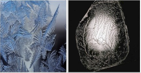
Fig. 1. Fractals occurring in nature by default.
In addition to the simplicity and self similarity, fractal curves have the additional property of approximately filling a plane, which makes them the attractive candidate for use in the design of the antennas [7].
IJSER © 2013 http://www.ijser.org
International Journal of Scientific & Engineering Research, Volume 4, Issue 8, August-2013 221
ISSN 2229-5518
2.1. FRACTAL AS ANTENNA
Fractal geometry is a very good solution to fabricate multiband and low profile antennas. Applying fractals to antenna elements allow for smaller size, multiband and broadband properties. Using the above properties a single
fractal antenna can be used for a all-in-one wireless device, thus allowing the services to be integrated in a better and cheaper way, which is the current demand in respect to antennas. Several UWB antenna configurations based on fractal geometries have been investigated including Koch, Sierpinski, Minkowski, Hilbert, Cantor and fractal tree antennas in recent years. However, fractal antenna structures-inspite of their apparent geometrical complexity- can br built and studied recursively according to various transformations from one scale to another [8], usine their interesting auto similarity property. Fractal loops have the characteristics that the perimeter increases to infinity while maintaining the volume occupied. This increase in length decreases the required volume occupied for the antenna at resonance. For a small loop, this increase in length improves the input resistance. By raising the input resistance, the antenna can be more easily matche to a feeding transmission line.
3. ANTENNA DESIGN.
In this paper, first a Sierpinski carpet antenna using microstrip line feeding is shown. It was made upto first iteration. The radiating elements were base on a copper clad material called FR-4. The simulation of the basic
structure resulted in an antenna size of 38.04mm ×
29.46mm. Figure 2 shows the design of a Sierpinski Carpet
fractal antenna starting with a rectangular geometry of
single patch antenna.
The model of the antenna is as shown in the Figure 3. As
shown in the figure, initial design, rectangular Sierpinski Carpet (dimensions described above for patch) is modeled. This antenna is designed upto first iteration.
To improve the characteristics further, stacked configuration of this square patch is modeled and
simulated. The stacked patch is shown in the Fig. 4. The dimension of the initial design was calculated using the microstrip design equations for rectangular microstrip antennas. Further, to obtain the impedance matching in both the cases, quarter wave transformer is used to match the load to the transmittion line. The dimensions calculated using the equations come out be 6.034 mm× 0.52 mm. The transformer is connected to 50Ω transmittion line to one end and to the patch at the another end providing impedance matching between the two and less power reflections from the output side to the load. Further, two stacked configurations are shown in the paper. First, there is no feed attached to the parasitic patch while in the second, there is a proper feed
Stage 0 stage 1
Stage 3
Fig. 2 : The stages iteration of Sierpinski carpet fractal antenna.
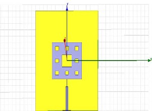
Fig. 3 : Sierpinski Carpet First iteration microstrip antenna.
, including the quarter wave transformer is attached to the parasitic patch. In the first case, the parasitic patch is solely driven by the electromagnetic coupling from the driven patch. It is necessary here to add that, the driven substrate has a dielectric constant as compared to the parasitic substrate, to enhance the fringing field [9]. A decrease in the dielectric constant will increase the ratio hi/lo [10]. In turn, this will increase the resonance frequency of the antenna and widens the operating bandwidth. In the stacked configuration, the lower substrate is chosen to be of FR_epoxy having a dielectric constant of 4.4 and the upper to be of Arlon Diclad 880 (tm), having a dielectric constant of 2.2. The stacked configuration is shown below.


IJSER © 2013 http://www.ijser.org
International Journal of Scientific & Engineering Research, Volume 4, Issue 8, August-2013 222
ISSN 2229-5518
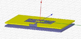
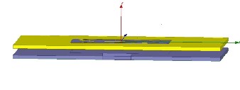
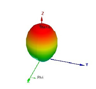
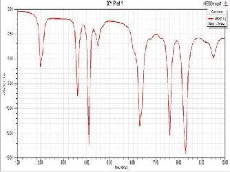
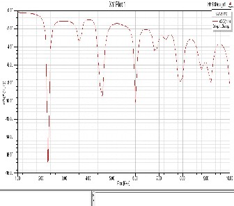
Fig 5.1. Return Loss(in dB’s) for First iteration Sierpinski Carpet Antenna.
Fig. 4. : Stacked Sierpinski carpet With (1)NO FEED for parasitic patch and (2) FEED for parasitic patch.
4. Results and Discussion.
The designed antennas are simulated with the help of simulation software Ansoft HFSS. The Stacked
configuration is having a sandwiched layer of air in between the upper and lower models. First, simulation of simple Sierpinski carpet is done. The return loss and radiation pattern is shown below in Fig.5. This antenna is showing resonance at frequencies 4.1, 6.3, 7.6 and 8.3 GHz. The return loss and the radiation pattern of stacked configuration is shown in Fig.6. for with feed and without feed respectively. From Fig.7.1, it is clearly shown that the frequency resonance is from 4.4 to 4.8 GHz i.e a bandwidth of 400 MHz. The increase in the frequency resonance of 4.1
GHz to 4.4 to 4.8 GHz may be accounted for the stacking and having a low dielectric constant for the parasitic patch.
Fig 5.2. 3-D Polar plot for for First iteration
Sierpinski Carpet Antenna.
This increase in bandwidth may be used in a variety of wireless devices using the UWB range for its operations. Further, one of the reasons for the return loss of Fig. 7.2 is the destructive interference. 3 D polar plots are also shown showing the three dimensional radiation patterns for the two antennas.
IJSER © 2013 http://www.ijser.org
International Journal of Scientific & Engineering Research, Volume 4, Issue 8, August-2013 223
ISSN 2229-5518
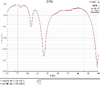
Fig.7.1 Return Loss for Stacked Antenna with electromagnetically coupled parasitic patch
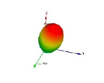
Fig.7.13 Radiation pattern for Stacked Antenna with electromagnetically coupled parasitic patch.
Fig.7.2 Return Loss for Stacked Antenna with having a feed for parasitic patch
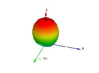
Fig.7.4 Radiation pattern for Stacked Antenna with having a feed for parasitic patch.
5. Conclusion.
Stacking of the antennas, keeping the dielectric constants of the parasitic and driven substrates to a suitable value,
increases the resonance frequency and the bandwidth of the antenna. The air gap sandwiched between the upper and
IJSER © 2013 http://www.ijser.org
International Journal of Scientific & Engineering Research, Volume 4, Issue 8, August-2013 224
ISSN 2229-5518
lower models is also a factor determining the important
characteristics of the antenna.
References
[1] S. J. Petko and D. Werner “Miniature rconfigurable three-dimensional fractal tree antennas”, IEEE Transactions on Antennas and Propagation. , Vol. 52, No. 8 , August 2004.
[2] C. Peunte, J. Romeu, R.Pous,X. Garcia, and F. Benitez “Fractal
mutiband antenna based on the Sierpinski gasket” Electron. Lett., Vol. 32, pp. 1-2, 1996.
[3] C. Peunte, J. Romeu, R.Pous and A. Cardama, “On the behaviour of the Sierpinski multiband fractal antenna”, IEEE Trans. Antennas Propag,, Vol 46, pp. 514-524, 1998.
[4] C.T.P.Song, P.S.Hall, H. Ghafouri Shiraz, and D. Wake, “Fratctal stacked monopole with very wide bandwidth” Electron. Lett., Vol
35, pp. 945-946, 1999.
[5] G.J.Walker and J.R.James, “ Fractal volume antennas”, Electronic
Lett., Vol. 34, pp. 1536-1537, 1998.
[6] B.B.Malderbrot, “ The Fractal geometry of nature, New York, W.H.Freeman, 1983.
[7] J. Geanvitorio and Y. Rahmat, “Fractal antennas : A novel antenna miniaturization technique and applications”, IEEE Antennas and Propagation Magazine, Vol 44, No. 1, February 2002.
[8] B. Malderbrot, “ Fractal objects”, Flammarion, 1975.
[9] M. F. M. Yosuf, I. P. Pohan, M. Esa, N. A. Murad and Y. E. Chuan, “Stacked square fractal antenna with improved bandwidth for wireless LAN access point”,International RF and Microwave Conference Proceedings, Malaysia, 2006.
[10] Waterhouse, R. B., Stacked patches using high and low dielectric constant material combinations, IEEE Transactions on Antennas and Propagations, Vol 47, No. 19, Nov 1999.
IJSER © 2013 http://www.ijser.org