International Journal of Scientific & Engineering Research, Volume 4, Issue 1,January-2013 1
ISSN 2229-5518
Improve WiMAX Network Performance Using Cross-Layer Framework B.Kharthika,G.M.Vigneswari
Abstract — W iMAX OFDMA downlink subframes have a special 2-D channel time structure. The resource allocations from this structure incur extra control overheads that hurt network performance. Existing solutions try to improve network performance by designing either the scheduler in the MAC layer or the burst allocator in the physical layer, but the efficiency of overhead reduction is limited. In this paper, we point out the necessity of “co- designing”(i.e.) both the scheduler and the burst allocator are combined. For that, we propose a cross-layer framework under the PUSC model. It covers overhead reduction, real-time and non-real-time traffic scheduling, and burst allocation .The framework includes a two-tier priority-based scheduler and a bucket-based burst allocator. By coupling these scheduler and burst allocator, it solves the problem of resource allocation for data traffic. By co- designing the scheduler and burst allocator, the scheduler can well utilize the frame space and, reduce IE overheads with the help of burst allocator. The burst allocator satisfy traffic requirements such as real-time delay constraints ,the burst allocator has to arrange bursts based on the traffic scheduling knowledge from the scheduler. and maintain fairness. Through analysis, the cross-layer framework significantly increases network throughput maintain its long-term fairness, alleviates real-time traffic delays, and enhances frame utilization.
Index Terms — Burst allocation, cross-layer design, fair scheduling,IEEE 802.16, W orldwide Interoperability for Microwave Access orthogonal frequency-division multiple access (W iMAX OFDMA).
—————————— ——————————
1 INTRODUCTION
The IEEE 802.16 standard has been developed for wide- range broadband wireless access. The physical (PHY) layer employs the orthogonal frequency-division multiple access (OFDMA) technique, where a basestation (BS) can simultaneously communicate with multiple mobile subscriber stations (MSSs) through a set of orthogonal sub channels. The standard supports the frequency-division duplex (FDD) and the time-division duplex (TDD). This paper aims at the TDD mode. Under the TDD mode, the following two types of subcarrier grouping models are specified: 1) adaptive modulation and coding (AMC) and 2) partial usage of subcarriers (PUSC).This paper adopts the PUSC model.
The BS manages network resources for MSS data traffic, which is classified into real-time traffic [e.g., unsolicited grant service (UGS), real-time polling service (rtPS), and extended real-time polling service (ertPS)] and non-real-time traffic [e.g.non-real-time polling service (nrtPS) and best effort (BE)].These network resources are represented by frames. Each frame consists of a downlink subframe and an uplink subframe. Each downlink subframe is a 2-D array over channel and time domains, as shown in Fig1. The resource unit that the BS allocates to MSSs is called a burst. Each burst is a 2-D subarray and needs to be specified by a downlink map information element (DL-MAP_IE or simply IE) in the downlink map (DLMAP) field. These IEs are encoded by the robust
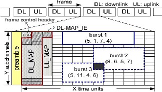
quaternary phase-shift keying (QPSK) 1/2 modulation and coding scheme (MCS) for reliability. Because the IEs occupy frame space and do not carry MSSs’ data, they are considered control overheads.These overheads affect network performance, because it determines frame utilization. To manage resources to all data traffic, the standard defines a scheduler in the medium access control (MAC) layer and a burst allocator in the PHY layer. Here the efficiency of overhead reduction is limited. This aims at the codesigning of both scheduler and burst allocator. Structure of an IEEE 802.16 OFDMA downlink subframe under the TDD mode as shown in fig.1 and the design of the scheduler and burst allocator consider the following issues. The design of these scheduler and burst allocator depends on each other.
Fig1. Structure of an IEEE 802.16 OFDMA downlink subframe under the TDD mode.
IJSER © 2013 http://www.ijser.org
International Journal of Scientific & Engineering Research, Volume 4, Issue 1,January-2013 2
ISSN 2229-5518
The design of the scheduler should consider the following three issues.
The scheduler should improve network throughput while maintaining long-term fairness.
The scheduler should satisfy the delay constraints of real-time traffic to avoid packet-dropping ratios.
To well utilize the limited frame space, the scheduler has to reduce IE overheads when assigning resources to MSSs data traffic.
On the other hand, the design of the burst allocator should address the following three issues.
The burst allocator should utilize the frame space and reduce the control overhead.
The burst allocator has to arrange bursts based on
the traffic scheduling knowledge from the scheduler.
Simplicity is a critical concern, because a frame is typically 5 ms , which means that the burst allocation scheme needs to be executed every 5 ms.
In prior studies design solely either the scheduler or the burst allocator to address the reduction of IE overheads. Nevertheless, we point out the necessity of the cross-layer design by the following three reasons. First, the amount of IE overheads highly depends on the number of scheduled MSSs and the number of fragmented bursts, where prior work handles the two issues by the scheduler and the burst allocator, respectively. However, if we only consider either issue, the efficiency of overhead reduction is limited. Second, without considering burst arrangements, the scheduler may fail to satisfy MSSs’ requirements, because extra IE overheads will occupy the limited frame space. Third, without considering the scheduling assignments, the burst allocator may kick out some important data of MSSs (due to out-of-frame space).This case may cause unfairness among MSSs and high packet dropping ratios of real-time traffic. Therefore, it is necessary to codesign both the scheduler and the burst allocator due to their inseparable dependency.
In this system cross-layer framework that contains
a two-tier priority-based scheduler and a bucket-based burst allocator. The scheduler assigns priorities to MSSs’ traffic in a two-tier manner and allocates resources to the traffic based on its priority. In the first tier, traffic is differentiated by its type. Urgent real-time traffic is assigned with the highest level-1 priority to avoid its packets being dropped in the next frame. Then, a γ ratio (0
< γ < 1) of nonurgent real-time traffic is assigned with level-
2 priority, and non-real-time traffic is given level-3 priority. The aforementioned design has two advantages. First, we
can avoid generating too much urgent real-time traffic in
the next frame. Second, non-real-time traffic can have opportunity to be served to avoid being starved. In the second tier, traffic of the same type (i.e., the same priority level in the first tier) is assigned with different priorities calculated by the following four factors.
1) Current transmission rates;
2) average transmission rates;
3) admitted data rates;
4) queue lengths.
The BS can have the knowledge of the aforementioned four factors, because all downlink traffic is queued in the BS, and MSSs will report their average channel qualities to the BS. The scheduler can adjust the number of MSSs to be served and assign resources to traffic according to the burst arrangement manner (from the burst allocator) to significantly reduce IE overheads.
On the other hand, the burst allocator divides the free
space of each downlink subframe into a special structure that consists of several “buckets” and then arranges bursts in a bucket-by-bucket manner. Given k requests to be filled in a subframe, we show that this burst allocation scheme generates at most k plus a small constant number of IEs. In addition, the burst allocator will arrange bursts according to the priority design from the scheduler so that the burst allocation can satisfy MSSs’ traffic requirements. The aforementioned bucket-based design incurs very low computation complexity and can be implemented on most low-cost Worldwide Interoperability for Microwave Access (WiMAX) chips. Explicitly, in our cross-layer framework, both the scheduler and the burst allocator are tightly coupled together to solve the problems of overhead reduction, real-time and non-real-time traffic scheduling, and burst allocation.
2 RESOURCE ALLOCATION PROBLEM
The BS has to arrange the radio resource to the MSSs according to their traffic demands. The radio resource is divided into frames. A downlink subframe is modeled by a
2D array with X time units (in the time domain) and Y
subchannels (in the frequency domain). The basic unit in the X × Y array is called a subchannel time slot (or simply a slot). Each downlink subframe is composed of the following three portions: 1) preamble; 2) control; and 3) data. The control portion contains a DL-MAP and an uplink map (UL-MAP) to indicate the downlink and uplink resource allocation in the current frame, respectively. The downlink allocation unit is a subarray, called a downlink burst (or simply a burst), in the X × Y array. Each burst is
IJSER © 2013 http://www.ijser.org
International Journal of Scientific & Engineering Research, Volume 4, Issue 1,January-2013 3
ISSN 2229-5518
denoted by (x, y, w, h), where x is the starting time unit, y is the starting subchannel, w is the burst’s width, and h is the burst’s height. An MSS can own more than one burst in a subframe. However, no two bursts can overlap with each other. Each burst requires one IE in the DL-MAP to describe its size and location in the subframe. According to the standard, each burst carries the data of exact one MSS. Explicitly, from the scheduler’s perspective; the number of bursts (and, thus, IEs) will increase when more MSSs are scheduled. The resource allocation problem is formulated as follows.
The fairness index (FI) in is adopted to evaluate the

long-term fairness of a scheme as follows:

Where SDi is the shared degree of Mi, which is calculated by
SDi=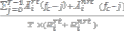
Āirt(x) and Āinrt(x) are the amounts of real-time and non- real-time traffic allocated to Mi in the xth frame, respectively, fc is the current frame index, and T is the window size(in frames), over which we measure fairness.
3 CROSS-LAYER FRAMEWORK
Figure2 shows the system architecture of our cross-layer framework, which is composed of the following two components: 1) the two-tier priority-based scheduler and
2) the bucket-based burst allocator.
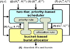
Fig2. System architecture of the proposed cross-layer framework.
The transmission rate Ci for each MSS Mi (see Fig2, label 1) is periodically reported to the scheduler and the
burst allocator. Each Mi’s admitted rates Rirt and Rinrt (see Fig2, label 2) are sent to the scheduler when Mi first associates with the BS or when Rirt and Rinrt change. The scheduler also monitors the current amounts of queued realtime and non-real-time data Birt and Binrt(see Fig2, label
3). The burst allocator informs the scheduler of the bucket
size Δbkt and the available free-space FS in the current downlink subframe (see Fig2, label 4) to help the scheduler distribute resources among MSSs’ traffic, where
FS = X × Y - (FCH size) - (UL_MAP size) - (size of
DL_MAP control fields)
where FCH is the frame control header. The UL- MAP size can be known in advance, because the uplink subframe is allocated before the downlink subframe. The DL-MAP control fields contain all parts of DL-MAP, except for IEs, which are yet to be decided by the burst allocator.
In cross-layer framework, the priority rule defined
in the scheduler helps the burst allocator determine how bursts can be arranged for MSSs’ traffic. On the other hand, the allocation rule defined in the burst allocator also helps the scheduler to determine how resources can be assigned to MSSs’ traffic. Both the priority and allocation rules are similar to tenons in the cross-layer framework, which make the scheduler and the burst allocator tightly cooperate with each other. Due to the NP-complete nature of the burst allocation problem and the hardware constraints of low- cost WiMAX chips, it is inefficient and yet infeasible to derive an optimal solution for arranging IEs and bursts in a short frame duration. Therefore, to keep our burst allocator simple and efficient, we adopt a bucket concept as follows. The available free-space FS in the current subframe is horizontally sliced into a number of buckets.

Fig.3. Example of bucket based burst allocation with three buckets and four resource assignments.
3.1 Two-Tier Priority-Based Scheduler
To generate these assignments, the scheduler adopts a two- tier priority rule. In the first tier, traffic is differentiated by
IJSER © 2013 http://www.ijser.org
International Journal of Scientific & Engineering Research, Volume 4, Issue 1,January-2013 4
ISSN 2229-5518
its type and is given priority levels according to the following order.
– P1: urgent real-time traffic whose packets will pass their
deadlines at the end of this frame;
– P2: real-time traffic ranked top γ ratio sorted by their importance;
– P3: non-real-time traffic sorted by their importance.
Then, in the second tier, traffic of the same type is assigned with different priorities by its importance, which is calculated by the following four factors:
1) current transmission rates;
2) average transmission rates;
3) admitted data rates;
4) queue lengths;
Assign resource to MSS
To summarize, our scheduler generates the resource assignment according to the following three priorities:
P1) urgent traffic;
P2) real-time traffic; and
P3) non-real-time traffic.
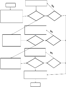
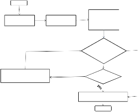
Fig.4.illustrates the flowchart of the scheduler. Step
1 first schedules MSSs with urgent traffic to alleviate their real-time traffic delays. Step 2 schedules the top γ ratio of MSSs to reduce the number of MSSs that may have urgent traffic in the following frames. This step also helps reduce the IE overhead of future frames caused by urgent traffic, which is neglected by prior studies. Step 3 schedules MSSs with lower non-real time satisfaction ratios to prevent them from starvation. Finally, step 4 reshapes all assignments.
This step will help the burst allocator fully utilize a
start
Sort MSS by their current
urgent traffic
Pick
success no
downlink subframe.
3.2 Bucket-Based Burst Allocator
txn rate in decreasing order
MSS FS>0?
fail
Step 1
start
Step 1 Step 2
Step 3
Sort resource
Assign resource to MSS
realtime traffic
Slice FS into buckets
Reserve slots for
IEs
assignments based on priorities
Sort MSS by their
importance of real
time data
Pick
MSS
fail
success
FS>0?
no Step 2
Pick resource allocation for rt and
Assign resource to MSS
non realtime traffic
Fill resource allocation of
nrt data
success
all
fail
Sort MSS by their
Pick
success
no Step 3
data into current bucket and
switch to next bucket no
buckets are full?
importance of non real
time data
.
MSS FS>0?
fail
Do fine tuning on the total resource assignment
end
Step 4
Step 4
Feed back actual allocations to the scheduler
end
Fig5. Flow chart of the Bucket based Burst allocator.
Fig4. Flow chart of the two-tier priority-based scheduler.
The aforementioned two-tier priority rule not only prevents urgent real-time traffic from incurring packet dropping (through the first tier) but maintains long-term fairness (through the second tier) as well. The network throughput is also improved by giving a higher priority to MSSs that use higher transmission rates (in the second tier). In addition, by giving a γ ratio of nonurgent real-time traffic with level-2 priority, the amount of urgent real-time traffic in the next frame can be reduced, and non-real-time traffic can have opportunity to send their data.
However, because the burst allocation problem is NP-complete, our bucket-based heuristic will try to squeeze as more MSSs’ assignments into FS as possible and allocate one burst per assignment with a very high possibility. If more than one burst is required, more IEs are needed, in which case, some assignments that were originally arranged by the scheduler may be trimmed down or even kicked out by the burst allocator.
The proposed scheduler and burst allocator are dependent on each other by the following two designs. First, the scheduler reserves the extra IE space caused by the bucket partition and arranges resources to MSSs’ traffic
so that the resource assignments can align to buckets. Thus,
IJSER © 2013 http://www.ijser.org
International Journal of Scientific & Engineering Research, Volume 4, Issue 1,January-2013 5
ISSN 2229-5518
we can enhance the possibility that the burst allocator fully satisfies the resource assignments from the scheduler. Second, the burst allocator follows the priority rule in the scheduler to arrange bursts. Thus, even if the frame space is not enough to satisfy all traffic, urgent real-time traffic can still be arranged with bursts to catch their approaching deadlines.
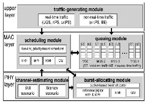
4 PERFORMANCE EVALUATION
To verify the effectiveness of our cross-layer framework, we develop a simulator in C++ based on the architecture as shown in Fig. 6. The simulator contains three layers: The traffic-generating module in the upper layer creates the MSSs’ demands according to their real-time and non-real- time traffic requirements. In the MAC layer, the queuing module maintains the data queues for each MSS and the scheduling module conducts the actions of the scheduler. In the PHY layer, the channel-estimating module simulates the channel conditions and estimates the transmission rate of each MSS, and the burstallocating module conducts the actions of the burst allocator. The arrows in Fig. 6 show the
4.1 Network Throughput
We first compare the network throughput under different number of MSSs (i.e., n), where the network throughput is defined by the amount of MSSs’ d ata (in bits) transmitted by the BS during 1000 frames. We observe the case when the network becomes saturated, where there are 60 ~ 90
MSSs to be served. Fig. 7 shows the simulation results under the Markov scenario. Explicitly, when the number of MSSs grows, the throughput increases but will eventually become steady when there are too many MSSs (i.e., n ≥ 80). The throughput under the SUI scenario is lower than the throughput under the Markov scenario, because some MSSs may move around the boundary of the BS’s coverage, leading to a lower SNR and, thus, a lower MCS. In particular, our cross-layer framework has the highest throughput in most cases because of the following two reasons. First, our scheduler assigns a higher priority to MSSs with higher Ci and Ci/Ciavg values and thus makes MSSs receive their data in higher transmission rates. Second, both our scheduler and burst allocator can effectively decrease the number of IEs and acquire more subframe space for data transmission.


ours HRF MPF
references. In addition, the scheduling and the burst- allocating modules will interact with each other,
particularly for our scheme.
60 70 80 90
Number of MSSs


RMF QG
We compare our cross-layer framework with the high-rate first (HRF) scheme, the modified proportional fair (MPF) scheme, the rate maximization with fairness consideration (RMF) scheme, and the QoS guarantee (QG) scheme.
Fig7. Comparison on network throughput.
When n = 90, our cross-layer framework will try to satisfy a large number of urgent traffic to avoid their packets being dropped. In this case, its throughput is slightly lower than the throughput of MPF, but our cross-layer framework can
significantly reduce the real-time packet-dropping ratio.
Fig 6. Architecture of our C++ simulator.
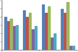
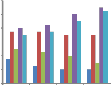
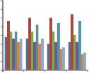
4.2 IE Overheads and Subframe Utilization
Figure8 shows the average number of IEs in each downlink subframe. HRF, RMF, and QG do not consider IE overheads; therefore, they will generate a large number of IEs. The situation becomes worse when the number of MSSs grows, because each MSS needs to be allocated with at least one burst (and, thus, one IE). By considering IE overheads in the scheduler, MPF can reduce the average number of IEs per frame. It can be observed that, when the number of MSSs grows, the number of IEs in MPF reduces.
IJSER © 2013 http://www.ijser.org
International Journal of Scientific & Engineering Research, Volume 4, Issue 1,January-2013 6
ISSN 2229-5518
The reason is that MPF allocates more resources to MSSs in a frame to reduce the total number of scheduled MSSs, thus reducing the number of allocated bursts (and IEs). In Fig.
9,our cross-layer framework generates the smallest number
of IEs per frame, because both the proposed scheduler and burst allocator consider IE overheads, and the framework can adjust the number of non urgent real-time traffic to be served to avoid generating too many bursts. IE overheads have a strong impact on the utilization of downlink subframes, as reflected in Fig.9. Because HRF, RMF, and QG generate a large number of IEs, their subframe utilization will be lower than MPF and our cross-layer framework. It can be observed that the number of buckets B significantly affects the subframe utilization of our cross- layer framework.
4.3 Long-Term Fairness
Next, we verify whether each scheme can guarantee longterm fairness under a highly congested network, where there are 140 ~ 200 MSSs. Fig. 10 shows the fairness indices (FI) of all schemes.Based on Fig. 10, HRF incurs the lowest index, because it always serves MSSs that use higher transmission rates. By considering the amount of allocated data of each MSS, MPF can have a higher index than HRF. QG and RMF try to satisfy the minimum requirement of each traffic in every frame, thus leading to higher indices. Because RMF allocates the resources to MSSs sorted by their transmission rates, its index will be lower than QG.
1
0.9
In particular, a very large B (e.g., 30) will reduce
the amount of data carried in each bucket and thus generate many small bursts. On the other hand, a very small B (e.g.,
1) may degrade the functionality of buckets, and thus, some
resource assignments may not fully utilize the bursts allocated to them. Based on Fig. 10, we suggest setting B = 5 to get the best utilization.
0.8
0.7
0.6
0.5
0.4
0.3
0.2
0.1
0
140 150 160 170 180 190 200
Number of MSSs


ours QG RMF MPF HRF
120
100
80
60
40
20
0
60 70 80 90
Number of MSSs


ours HRF MPF RMF QG
Fig. 10. Comparison on long-term fairness.
Our cross-layer framework has the highest FI due to the following two reasons. First, our priority-based scheduler only schedules γ ratio of nonurgent real-time traffic to avoid starving non-real-time traffic. Second, our cross-layer framework tries to reduce the IE overheads and acquire more frame space to allocate bursts for MSSs’ traffic. In this case, we have more resources to fairly distribute among MSSs. Thus, our cross-layer framework can maintain long-term fairness, even in a highly congested
network.
.
1
0.95
0.9
0.85
0.8
0.75
0.7
0.65
0.6
Fig. 8. Comparison on IE overheads.


 ours(B=1) ours(B=5) ours(B=30)
 HRF
HRF

MPF
60 70 80 90
 RMF
RMF
Number of MSSs
 QG
QG
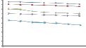
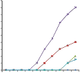
4.4 Packet-Dropping Ratios of Real-Time Traffic
We then observe the packet-dropping ratios of real- timetraffic, where each MSS will generate 0 ~ 2Rirt real-time data in each frame. When a real-time packet is not transmitted within 6 frames (i.e., 30 ms) after being generated, it will be dropped. Fig. 11 shows the real-time packet-dropping ratios of all schemes under 10 ~ 110 MSSs. Both HRF and MPF distribute resources to MSSs based on the transmission rates without considering the traffic types; therefore, their ratios begin raising when n ≥ 50. In this case, a large amount of non-real-time traffic will compete with real-time traffic for the limited resource. On the other hand,
the ratios of RMF and QG begin raising when n ≥ 90.
Fig. 9. Comparison on subframe utilization.
Because both RMF and QG try to satisfy the minimum requirements of all traffic in each frame, they can avoid
IJSER © 2013 http://www.ijser.org
International Journal of Scientific & Engineering Research, Volume 4, Issue 1,January-2013 7
ISSN 2229-5518
real-time packet dropping when the network is not saturated (i.e., n < 90). Our cross-layer framework can have almost zero ratio due to the following three reasons. First, our priority-based scheduler assigns urgent real-time traffic with the highest priority. In addition, it schedules a γ ratio of nonurgent real-time traffic to avoid generating too many urgent traffic in the following frames. Second, our bucket- based burst allocator arranges bursts based on the priorities from the scheduler; therefore, the bursts of the urgent real- time traffic can first be allocated to avoid packet dropping. Third, both our scheduler and burst allocator try to reduce IE overheads, and thus, more urgent real-time traffic can be served in each frame.
Allocation in IEEE 802.16 OFDMA Networks” IEEE
transactions on vehicular technology, vol. 60, no. 4, may
2011.
[2] B. Rong, Y. Qian, and H. H. Chen, “Adaptive power allocation and call admission control in multiserviceWiMAX access networks,” IEEE Wireless Commun., vol. 14, no. 1, pp.
14–19, Feb. 2007.
[3] K. Sundaresan and S. Rangarajan, “Efficient algorithms for leveraging spatial reuse in OFDMA relay networks,” in Proc. IEEE INFOCOM, 2009, pp. 1539–1547.
[4] Y. Ben-Shimol, I. Kitroser, and Y. Dinitz, “Two-dimensional mapping for wireless OFDMA systems,” IEEE Trans. Broadcast., vol. 52, no. 3, pp. 388–396, Sep. 2006.
1
0.9
0.8
0.7
0.6
0.5
0.4
0.3
0.2
0.1
0
Number of MSSs


ours HRF MPF RMF QG
[5] H. S. Kim and S. Yang, “Tiny MAP: An efficient MAP in IEEE 802.16/WiMAX broadband wireless access systems,” Comput. Commun., vol. 30, no. 9, pp. 2122–2128, Jun. 2007.
[6] Y. Ma and D. Kim, “Rate-maximization scheduling schemes for uplink OFDMA,” IEEE Trans. Wireless Commun., vol. 8, no. 6, pp. 3193–3205, Jun. 2009.
[7] J. Shi and A. Hu, “Maximum utility-based resource allocation algorithm in the IEEE 802.16 OFDMA system,” in Proc. IEEE ICC, 2008, pp. 311–316.
Fig. 11. Comparison on real-time packet-dropping ratios under different numbers of MSSs.
5 CONCLUSION
A cross-layer framework that covers the issues of overhead reduction, real-time and non-real-time traffic scheduling, and burst allocation in an IEEE 802.16 OFDMA network. Scheduler reduces potential IE overheads by adjusting the number of MSSs to be served. With a two-tier priority rules, it guarantees real-time traffic delays, ensures satisfaction ratios of non-real-time traffic, and maintains long-term fairness. On the other hand, burst allocator incurs low complexity and guarantees a bounded number of IEs to accommodate data bursts. In addition, it follows the priority rule from the scheduler to avoid packet dropping of urgent real-time traffic. We have also analyzed the impact of the number of buckets on the throughput loss. For future work, we will investigate how we can optimize the scheduler and burst allocator for some particular cases, e.g., various traffic Characteristics and MSS densities.
REFERENCES
[1] Jia-Ming Liang, Jen-Jee Chen, You-Chiun Wang, Member, and Yu-Chee Tseng, IEEE “A Cross-Layer Framework for Overhead Reduction, Traffic Scheduling, and Burst
[8] R. Pitic and A. Capone, “An opportunistic scheduling scheme with minimum data-rate guarantees for OFDMA,” in Proc. IEEE WCNC, 2008, pp. 1716–1721.
[9] N. A. Ali, M. Hayajneh, and H. Hassanein, “Cross-layer scheduling algorithm for IEEE 802.16 broadband wireless networks,” in Proc. IEEE ICC, 2008, pp. 3858–3862.
[10] J. Kim, E. Kim, and K. S. Kim, “A new efficient BS scheduler and scheduling algorithm in WiBro systems,” in Proc. IEEE ICACT, 2006, vol. 3, pp. 1467–1470.
[11] T. Wang, H. Feng, and B. Hu, “Two-dimensional resource allocation for OFDMA system,” in Proc. IEEE Int. Conf. Commun. Workshops, 2008, pp. 1–5.
[12] T. Ohseki, M. Morita, and T. Inoue, “Burst construction and packetmapping scheme for OFDMA downlinks in IEEE
802.16 systems,” in Proc. IEEE GLOBECOM, 2007, pp. 4307–
4311.
[13] X. Perez-Costa, P. Favaro, A. Zubow, D. Camps, and J. Arauz, “On the challenges for the maximization of radio resources usage in WiMAX networks,” in Proc. IEEE CCNC, 2008, pp.
890–896.
[14] A. Erta, C. Cicconetti, and L. Lenzini, “A downlink data region allocation algorithm for IEEE802.16e OFDMA,” in Proc. IEEE Int. Conf. Inf., Commun. Signal Process., 2007, pp. 1
IJSER © 2013 http://www.ijser.org