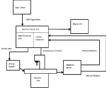
Fig.1 Basic block diagram of CNC machine
This includes brief explanation of the computerized Nu-
International Journal of Scientific & Engineering Research, Volume 5, Issue 7, July-2014 277
ISSN 2229-5518
Implementation of PLC for CNC Flame cutting machine
1Harshitha N, 2S M Narasimhan
1PG Student (M.Tech) E&E Dept., The National Institute of Engineering, Mysore, Karnataka, India
2Prof. E&E Dept., The National Institute of Engineering, Mysore, Karnataka, India
Abstract— In this modern era where everything is becoming automated, the business sector especially the manufacturing companies have gained so many benefits from using machines and technology to increase their profits and productivity rate.This paper presents Implementation of PLC logic for CNC flame cutting machine. And it involves the implementation of the hardware and software for CNC system i.e. development of PLC logic for CNC flame cutting machine and designing of circuit for interfacing of CNC System to the Flame cutting Machine. CNC Flame cutting Machines are automated that make Industrial components with less human interaction. Computer is used for processing of data and controlling various activities of the machine. PLC interfaces the Machine and the System. A great level of accuracy and speedier cycle times can be gained with the use of a CNC machine. Since this automation has a high repeatability, it can increase the consistency and yield.
Index Terms— Computerized Numerical Control (CNC), Distributed Numerical Control (DNC), Flame cutting machine, FAGOR CNC 8037, KeyCF, Numerical control (NC), Programmable Logic Controller (PLC),
—————————— ——————————
odern precision manufacturing demands extreme di- mensional accuracy and surface finish. Such perfor- mance is very difficult to achieve manually, even with
expert operators. In cases where it is possible, it takes much higher time due to the need for frequent dimensional meas- urement to prevent overcutting. It is thus obvious that auto- mated motion control would replace manual “hand wheel” control in modern manufacturing. Development of computer numerically controlled (CNC) machines has also made possi- ble the automation of the machining processes with flexibility to handle production of small to medium batch of parts. [1]
In this paper, a new controlling system topology is pro- posed for Flame cutting machine. i.e., Computerized Numeri- cal Control system is proposed for flame cutting machine. It involves the implementation of the hardware and software for CNC system i.e. development of PLC logic for CNC flame cut- ting machine and designing of circuit for interfacing of CNC System. The selected CNC system is FAGOR CNC
8037/Spain machine.
The CNC is prepared to be used in industrial environ-
ments, especially on milling machines, lathes, etc. The CNC
can control machine movements and devices.The Computer-
ized Numerical Control (CNC) machine makes use of comput-
er for processing of data and controlling various activities of
the flame cutting machines. This system the actions are con-
trolled by the direct insertion of numerical data at some point.
The system must automatically interpret portion of this data.
The CNC system receives numerical data, interpret the data
and then control the action accordingly.
Computerized Numerical Control (CNC) is a specialized
and versatile form of soft automation and its applications cov-
er many kinds, although it was initially developed to control
the motion and operation of machine tools. Computerized
Numerical Control may be considered to be means of operat-
ing a machine through the use of discrete numerical values fed
into the machine, where the required ‘input’ technical infor- mation is stored on a kind of input media such as hard disk, CD ROM, DVD, USB flash drive, or RAM card etc. The ma- chine follows a predetermined sequence of machining opera- tions at predetermined speeds necessary to produce a work piece of the right shape and size. [1],[2],[3],[7].
Fig.1 Basic block diagram of CNC machine
This includes brief explanation of the computerized Nu-
IJSER © 2014 http://www.ijser.org
International Journal of Scientific & Engineering Research, Volume 5, Issue 7, July-2014 278
ISSN 2229-5518
merical Control (CNC) system and its parts, with the help of a block diagram and required system specifications, technical specifications, and its parts. [fig.1]
CNC machine system consists of following sub systems:
2.1 Input Device:
The methods of loading the input to the system were as fol- lows:
• Manual Entry: The program generated by the AutoCAD is taken and loaded into the CNC machines for the pro- duction of a work piece manually.
• Serial port programming: Loading of programs on the CNC machine is done using RS232 protocol and line driv- er through RS232 port.
• External hard drives: The programs can be copied from the DNC system to the CNC flame cutting machines using pen drives.
2.2 Feedback Devices:
In order to have a CNC machine operating accurately, the positional values and speed of the axes need to be constantly updated. Two types of feedback devices are normally used. They are positional feedback device and velocity feedback device.
• Positional feedback devices: There are two types of positional feedback devices i.e. A linear transducer, which is used for direct positional measurement and rotary en- coder for angular (or indirect linear measurement).
• Velocity feedback devices: The actual speed of the mo- tor can be measured in terms of voltage generated.
2.3 Display Unit (Monitor):
The Display Unit serves as an interactive device between the machine and the operator. When the machine is running, the display unit displays the present status such as the posi- tion of the machine slide, the feed rate, the part programs, etc. It also shows the graphics simulation of the tool path so that part programs can be verified before the actual machining.
2.4 Machine Control Unit (MCU):
The machine control Unit is the heart of the CNC sys- tem.
There are two sub-units in the MCU: the Data Processing
Unit (DPU) and the Control Loop Unit (CLU).
• DPU : receiving a part program, the DPU firstly in- terprets and encodes the part program into internal machine tools
• CLU :The data from the DPU are converted into elec- trical signals in the CLU to control the driving system to perform the required motions
2.5 Machine Tool:
This can be any type of machine tool or equipment, in order to obtain high accuracy and repeatability.
2.6 Driving System:
The driving system is an important component of a CNC
machine as the accuracy and repeatability depend very much
on the characteristics and performance of the driving system. The requirement is that the driving system has to respond ac- curately according to the programmed instructions.
The input given to the system can be either through Manual Entry or programs can be loaded onto the CNC system. In order to have a CNC machine operate accurately, the positional values and speed of the axes feedbacks of the cutting machine are need to be constantly updated. The driving system has to response accurately according to the programmed instructions. The Display Unit acts as an interactive device between the machine and the operator. When the machine is running, the display unit displays the present status such as the position of the machine slide, feed rate, part programmes, etc. It also shows the graphics simulation of the tool path so that part programmes can be verified before the actual machining. The basic Block diagram depicting the working principle of the CNC Flame cutting Machine is shown in the fig 2.
Fig 2. Working Principle of CNC Flame Cutting Machine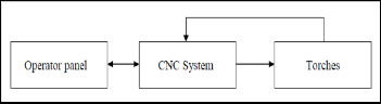
There are various valid reasons for the popularity of the CNC
machines are;
1. CNC machines can be used continuously 24 hours a day,
365 days a year and only need to be switched off for
occasional maintenance.
2. CNC machines are programmed with a design which can
then be manufactured hundreds or even thousands of
times. Each manufactured product will be exactly the same.
3. Less skilled/trained people can operate CNCs unlike manual flame cutting machines need skilled engineers.
4. CNC machines can be updated by improving the
software used to drive the machines
5. Training in the use of CNCs is available through the use
of „virtual software‟. This is software that allows the operator to practice using the CNC machine on the screen of a computer.
6. CNC machines can be programmed by advanced design
IJSER © 2014 http://www.ijser.org
International Journal of Scientific & Engineering Research, Volume 5, Issue 7, July-2014 279
ISSN 2229-5518
software such as Pro/DESKTOP®, enabling the manufacture of products that cannot be made by manual machines, even those used by skilled designers / engineers.
7. Modern design software allows the designer to simulate the manufacture of his/her idea. There is no need to make a prototype or a model. This saves time and money.
8. One person can supervise many CNC machines as once they are programmed they can usually be left to work by themselves. Sometimes only the cutting tools need replacing occasionally.
9. A skilled engineer can make the same component many
times. However, if each component is carefully studied, each one will vary slightly. A CNC machine will manufacture each component as an exact match.
The PLC program (PLC_PRG) may be edited at the front panel or copied from the hard disk or from a peripheral device or PC.
The PLC program (PLC_PRG) is stored in the internal CNC memory with the part-programs and it is displayed in the program directory (utilities) together with the part- programs.
Before executing the PLC_PRG program, it must be com- piled. Once it is done compiling, the CNC requests whether the PLC should be started or not.
To make the operator life easier and avoid new compilations, the source code generated at each compilation is stored in memory.
After power-up, the CNC acts as follows:
1. If there is an executable program stored in memory, it executes it (RUN).
2. If there is no executable program, but there is a PLC_PRG in memory, it compiles it (COMPILE) and executes it (RUN).
3. If there is no PLC_PRG in memory, it looks for it in the hard disk (KeyCF). If it is there, it compiles it (COMPILE) and executes it (RUN). If it is not there, it does nothing. Later on, when accessing the Jog mode, Execution mode, etc. the CNC will issue the corre- sponding error message.
Once the program has been compiled, it is not neces- sary to keep the source program (PLC_PRG) in memory be- cause the PLC always executes the executable program.
The PLC has 512 inputs and 512 outputs. Some of them, depending on the CNC configuration, communicate with external devices.
There is an exchange of information between the CNC and the PLC which is done automatically and the system has a series of commands which allow the following to be done quickly and simply:
• The control of Logic CNC inputs and outputs by means of an exchange of information between both systems.
• The transfer from the CNC to the PLC of M, S and T
auxiliary functions.
• To display a screen previously defined by the user, as
well as generating messages and errors in the CNC.
• Read and modify internal CNC variables from the
PLC.
• Access all PLC resources from any part-program.
• Monitor PLC resources on the CNC screen.
• Access to all PLC variables from a computer, via DNC
and through the RS 232 C serial line. [5], [6].
6.1 Inputs (I): They are elements that provide information to the PLC on the signals they receive from the outside world. They are represented by the letter I and there are 512 inputs available.
6.2 Outputs (O): They are elements that let the PLC acti-
vate or deactivate the various devices of the electrical
cabinet. These are represented by the letter O and there
are 512 outputs available.
6.3 Marks (M): These are elements capable of memorizing
in one bit (as if it were an internal relay) the status of
the different internal variables of the CNC (information
of the logic outputs received in the Communication be-
tween the CNC and the PLC of the CNC) and the sta- tus of the different variables of the PLC, whether these are internal or established by the user. They are repre- sented by the letter M, and there are 3999 user marks
and other special marks.
6.4 Registers (R): These are elements which allow a nu-
merical value to be stored in 32 bits or facilitate CNC-
PLC communication with the Logic CNC inputs and
outputs. They are represented by the letter R and there
are 256 user registers and other special registers.
6.5 Timers (T): These are elements which, once activated,
alter the status of their output for a specific time (time
constant). They are represented by the letter T, and there are 512 timers.
6.6 Counters (C): They are elements capable of counting up
or down a preset amount of events. They are repre-
sented by the letter C and there are 256 counters.
IJSER © 2014 http://www.ijser.org
International Journal of Scientific & Engineering Research, Volume 5, Issue 7, July-2014 280
ISSN 2229-5518
The PLC executes the user program cyclically. In other words, once it executes the complete program, it restarts running this program from the first instruction. [Fig 3]
Fig. 3 PLC program execution
This cyclic processing of the program is done as follows:
1) At the beginning of the cycle, PLC’s “I” resources are
assigned the current values of the physical inputs (con-
nectors). For example, if the physical input I10 is at 24V,
the PLC sets the I10 resource to "1".
2) It allocates the current values of the logic CNC out-
puts (CNCREADY, START, FHOUT, etc.) to PLC re- sources M5500 thru M5957 and R550 thru R562.
3) It runs the program cycle. The following sections in- dicate how the PLC program is structured and which are its execution modules.
4) After executing the cycle, it updates the Logic CNC inputs (/EMERGEN, /STOP, /FEEDHOL, etc.) with the current values of PLC resources M5000 thru M5465 and R500 thru R505.
5) It assigns the current values of the PLC’s “O” re- sources to the physical outputs (connectors). For example, if the "O5" resource is at "1", the PLC sets physical output O5 (connector) to 24V.
6) The cycle ends and is ready for the next scan. Bear in
mind that all the actions of the program executed by the
PLC alter the status of its resources.
Example: I10 AND I20 = O5
When this condition is met [resource I10 is "1" and I20 is
also "1"], the PLC sets resource "O5" to "1". If this condi-
tion is not met, the PLC sets resource "O5" to "0".
Therefore, the status of a resource may change during the
execution of the PLC program.
Example, assuming that the initial status of resource M100
is "0":
M100 AND I7 = O3
Resource M100 = "0"
I10 = M100
M100 takes the value of resource I10
M100 AND I8 = M101
The value of M100 depends on the previous instruction.
The program to be executed by the PLC consists of a series of modules which are appropri- ately defined by means of direct- ing instructions.
The modules which can make up the program are:
a) Main module (PRG)
b) Periodic execution module
(PE)
c) First cycle module (CY1)
Each module must begin with
the directing instruction which defines it (PRG, PE, CY1) and
end with the directing instruction END. Should the main pro-
gram contain the main module only it is not necessary to place
the instructions PRG and END.
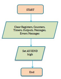
8.1 First cycle module (CY1):
This module is optional and will only be executed when the PLC is turned on. It is used to initialize the different resources and variables with their initial values, before pro- ceeding to execute the rest of the program.
This module operates by default with the real values of re- sources I, O, M. It is not necessary for this to be at the begin- ning of the program, but must always be preceded by the in- struction CY1.
8.2 Main module (PRG):
This module contains the user program. It will be executed cyclically and will be given the task of analysing and modify- ing CNC inputs and outputs. This module operates by default with the image values of resources I, O, M. There can only be one main program and this must be preceded by the instruc- tion PRG. It is not necessary to define it if it starts on the first line.
8.3 Periodic execution module (PE t):
This module is optional and will be executed every period of time t indicated in the directing instruction defining the module. This module may be used to process certain criti- cal inputs and outputs which cannot be checked or updated properly in the body of the main program due to its extended execution time.
Another application for this module is for those cases where specific tasks need not be evaluated at every PLC pro- gram cycle. Those tasks would be programmed in the periodic module and they would be executed with the frequency estab- lished by the execution time assigned to this module
Every time the PLC program is started (command RUN)
the first module to be executed is the first cycle module (CY1).
IJSER © 2014 http://www.ijser.org
International Journal of Scientific & Engineering Research, Volume 5, Issue 7, July-2014 281
ISSN 2229-5518
Once execution has been completed, it will continue with the main module (PRG).The main module will be executed cycli- cally until the execution of the PLC has stopped (command STOP). [5], [6].The periodic module will be executed every time the time indicated in the directing instruction “PEt” elapses. This count starts when the execution of the main module (the first time) begins.
The periodic module is processed as follows:
1. The PLC takes into account the current values, as just
before executing the PE module, of the local physical inputs
(connectors of the central unit).
2. Executes the periodic module.
3. It assigns the current values of the PLC’s ”O” re-
sources to the local physical outputs (connectors of the central
unit).
4. It ends the execution of the Periodic Module and re-
sumes the execution of the main module.
9 HARDWARE AND SOFTWARE DESCRIPTION
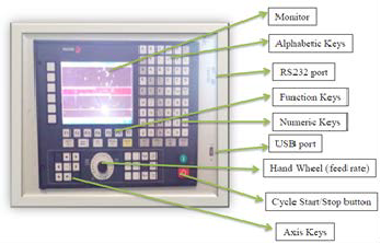
9.1 CNC monitor, keyboard and operating panel
Fig 4 CNC Monitor and Keyboard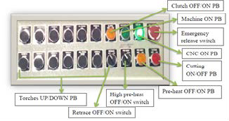
Fig 5 Operating panel
The schematic monitor, keyboard and operating panel is
shown in fig 4 and 5. The CNC The central unit is located on the rear of the monitor. Operating panel contains few switches for torch movement and for manually controlling the flame
cutting operation. The Knob (hand wheel) is used to adjust the feed rate which is nothing but the adjustment of the motor speed. To the left of the knob we can see few switches which are used to manipulate the X and Y axis movements. Cycle start/Stop button is used to start/stop the movement of ma- chine.
9.2 Control panel
Fig 6. Control panel with Accessories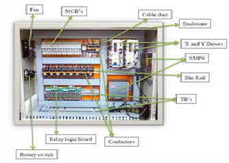
The schematic of control panel is shown in fig 6. Ratings of
all components are shown in table 1;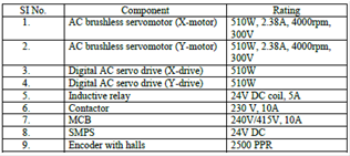
Table 1: Components ratings
9.3 Hardware Circuit Interface
The hardware circuit connection of CNC flame cutting ma- chine is shown in figure 7. Its hardware and software re- quirements are as follows;
Hardware Required
• CNC system
• RS232 cables
• Velocity Feedback units
• Positional Feedback units
• Power Supply unit
• Measuring Board
• Command Board
• I/O Boards
• Flame cutting torches
• Rail structures.
IJSER © 2014 http://www.ijser.org
International Journal of Scientific & Engineering Research, Volume 5, Issue 7, July-2014 282
ISSN 2229-5518
Software Required
• Operating System
• PLC
• CNC net.exe
• Auto CAD-2010
• MOST 2D
• BEML CAM
• Win DNC
9.4 System Configuration
Hardware Configuration:
• Configuration of the CNC 8037
• Power supply
• CPU-CNC power PC module
• Axes 2
• Digital video
• CNC resources
• RAM memory (kb)
• User 1024
• System 1024
• SDRAM PPC (Mb) 64
• PLC resources
• PLC integrated in CPU-CNC
• Local: 56 I, 32 O
Software Configuration:
• Maximum number of axes-3
• Tool radius compensation
• DNC
• Retrace
• Setup assistance
• Ethernet
9.5 CNC-PLC Communication
With the data exchange between the CNC and the PLC, it is possible to:
1. The control of logic inputs and outputs from the CNC by means of an exchange of information between both systems, which is done periodically and by means of specific PLC Marks and Registers.
2. The transfer from the CNC to the PLC of M, S and T
auxiliary functions.
3. Display screens which have been defined previously
by the user, as well as generating messages and errors
in the CNC, by means of specific PLC Marks.
4. Read and modify internal CNC variables from the
PLC.
5. Access all PLC resources from any part-program.
6. Monitor PLC resources on the CNC screen.
7. Access to all PLC variables from a computer, via DNC
through the RS 232 C serial line.
10.1 PLC logic flowchart
A graphical representation of an algorithm is often used in design phase of programming to work out the log- ical flow of a program. The logic is divided into various
Fig 7. Circuit interface diagram of CNC flame cutting ma-
subsections that are intended to perform a particular task. The flowcharts are written as per ladder program.
Flowchart – 1: First cycle module
IJSER © 2014 http://www.ijser.org
International Journal of Scientific & Engineering Research, Volume 5, Issue 7, July-2014 283
ISSN 2229-5518
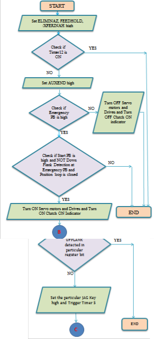
Flowchart – 2: Main PLC program
IJSER © 2014 http://www.ijser.org
Flowchart – 3: Axis Jag keys
Flowchart – 4: Torches UP/DOWN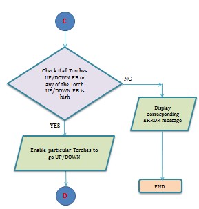
Flowchart – 5: Valve operation M codes
International Journal of Scientific & Engineering Research, Volume 5, Issue 7, July-2014 284
ISSN 2229-5518
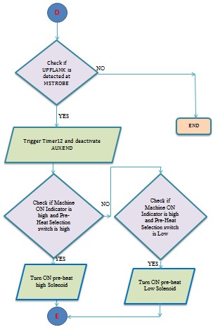
Flowchart – 6: Manual high pre-heat OFF/ON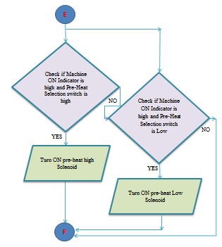
IJSER © 2014 http://www.ijser.org
Flowchart –7: Manual pre-heat OFF/ON
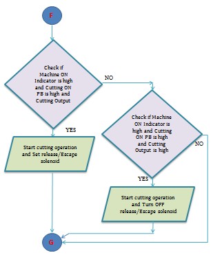
Flowchart –8: Cutting Oxygen ON/OFF
International Journal of Scientific & Engineering Research, Volume 5, Issue 7, July-2014 285
ISSN 2229-5518

Flowchart –9: PLC errors and messages 
Control object needed for CNC flame cutting machine is achieved by Programmable logic controller. Structure text logics written for the process is working satisfactorily.
Torch - 1 up operation:
Validation of ladder logic done is shown in
The first cycle module ladder program is shown below.
Table NO. 1
Table NO 1. Result
Similarly, the PLC is giving output for all other opera- tions of the CNC flame cutting machine.
The required part Program is either directly entered through the operator panel or retrieved via DNC Connection in the form of a CAD Drawing.
The metal work pieces of required dimensions are drawn using CAD Tool. Then the drawing is converted in to part program using BEML KAM software. These converted part programmes are then transferred to CNC system via DNC connection.
The program is selected on the CNC system and it is executed. Thus, the Metal plate is cut accurately with required dimensions. Thus, the PLC which is integrated with in the CNC System helps in moving the torches more accurately and the dimension of the obtained metal work piece is accurate.
IJSER © 2014 http://www.ijser.org
International Journal of Scientific & Engineering Research, Volume 5, Issue 7, July-2014 286
ISSN 2229-5518
This paper presents, one of the advanced system con- troller for CNC flame cutting machine and designing of circuit for interfacing of CNC System to the Flame cutting Machine. Compared to other conventional Numerical Control system, CNC is an advanced system and it makes the Industrial com- ponents with less human interactions. Computer system is used for processing of data and controlling various activities of the machine. The proposed system is FAGOR 8037/SPAIN.
The user enters the part program manually through the
Operator panel or select and edit a part program which is al- ready present in CNC Memory. The CNC System processes the machine parameters and sends the required input to the PLC. Thus the PLC controls the movement of the torches and other machining operations with the help of the feedback de- vices. There are two feedback devices used, one is the posi- tional Feedback which is obtained from the motors to the Axis drives regarding the position of the Motors and direction of Motion. The other one is the Velocity Feedback which is feed back to CNC System which gives the current velocity of the Motors which is maintained by controlling the pulses generat- ed from an encoder.
The main features of the system are as follows:
1) CNC machine can be used continuously, only need to be switched off for maintenance.
2) Each manufactured product will be exactly the same.
3) Less skilled or trained people can operate
4) Can be updated by improving software
5) Virtual software is available
[1] CNC Machines ,Version 2 EE IIT, Kharagpur
[http://nptel.ac.in/courses/Webcourse- con- tents/IIT%20Kharagpur/Industrial%20Automation%2
0control/pdf/L-
23(SM)%20(IA&C)%20((EE)NPTEL).pdf]
[2] An introduction to CNC machining, David Gibbs. [3] http://en.wikipedia.org
[4] Siegel, Arnold. "Automatic Programming of Numeri- cally Controlled Machine Tools", Control Engineering, Volume 3 Issue 10 (October 1956), pp. 65–70.
[5] FAGOR CNC 8037 installation manual
[6] FAGOR CNC 8037.M Programming manual
[7] Qiao Dongkai ; Coll. of Electr. Power, South China Univ. of Technol., Guangzhou, China ; Yang Xiang- yu ; Jia Jinxin “The Application of PLC to CNC Ma- chine Tools Development” IEEE trans. Digital Manu- facturing and Automation (ICDMA), 2011 Second In- ternational Conference on 5-7 Aug. 2011.
[8] Beaty, H. Wayne, Standard Handbook for Electrical
Engineers, '14th ed., McGraw-Hill, 1999, ISBN 0-07-
022005-0.
[9] W. Bolton, Programmable Logic Controllers, Fifth Edition, Newnes, 2009 ISBN 978-1-85617-751-1, Chap- ter 1
[10] Smid, Peter (2008), CNC Programming Handbook
(3rd ed.), New York: Industrial Press, ISBN
9780831133474, LCCN 2007045901.
IJSER © 2014 http://www.ijser.org