International Journal of Scientific & Engineering Research Volume 2, Issue 10, October-2011 1
ISSN 2229-5518
Implementation of Cascade Multilevel Inverter in
Distribution Systems as Power Line Conditioner
Rajasekhar.G.G, N.Sambasiva Rao, T.Vijay Muni
Abstract— This paper deals with the implementation of cascade multilevel inverter-based STATCOM, which employs H-bridge inverter. The STATCOM system is modeled using the d-q transform, which calculates the instantaneous reactive power. In this paper, a power line conditioner using a cascade multilevel inverter is presented for voltage regulation, harmonic filtering and reactive power compensation (var). 11 level STATCOM is selected as demonstration. The cascade multilevel converter consists of five single-phase full bridges in which each bridge has its own DC source. This new inverter can: 1) It can eliminate transformers of multilevel inverters used in conventional static var compensators; 2) make possible to direct connect to power distribution system in parallel and series without any transformer; 3) generate almost sinusoidal voltage. This paper focuses on feasibility and control schemes of the cascade inverter foe voltage regulation and harmonic filtering in distribution systems. The results are analyzed and discussed.
Index Terms— Active power filter, STATCOM, cascade multilevel inverter, power line conditioner,
—————————— ——————————
1 INTRODUCTION
N large power network, the active control of reactive power is indispensable to stabilize the power systems and to maintain the supply voltage. A static synchronous compen- sator (STATCOM) using the voltage source inverters (VSIs) have been widely accepted as the next generation of the reac- tive power controllers of power system. Recently, power quali- ty and custom power have been hot topics because of wide- spread use of nonlinear electronic equipment and the power quality requirements of sensitive loads. To provide high power quality at the point of common coupling (PCC) of distribution system, line conditioning, including voltage regulation, reac- tive power compensator, harmonic compensator is an indis-
pensably necessary remedy.
Traditionally, a multipulse inverter consisting of several vol- tage source inverters connected together through zig-zag ar- rangement transformers is used for var compensation. These transformers are: 1) most expensive equipment in the system;
2) produce about 50% of the total losses of the system; 3) causes difficulties in control due to dc magnetizing and surge over voltage problems resulting from saturation of the transformers.
A cascade multilevel inverter have been proposed for static var compensation and generation applications, The new cas- caded inverter eliminates the bulk of transformers required by static var compensators (SVC’s) that employ the multipulse inverter and that can respond much faster. This inverter gene- rates almost sinusoidal staircase voltage with only one time switching per line cycle.
.
2 SYSTEM CONFIGURATION OF POWER LINE
CONDITIONER
The proposed power line conditioner is using the cascaded multilevel inverter is presented for voltage regulation, reactive power (var) compensation and harmonic filtering of a power distribution system in this paper. A STATCOM is connected to
the power network at PCC, where the voltage-quality problem is concern. All required voltages and currents are measured and fed into the controller to be compared with the commands. The controller then performs feedback control and outputs a set of switching signals to drive the main semiconductor switches of the power converter accordingly. The single line diagram of the STATCOM system is illustrated in Figure 2-1. In general, VSC is represented by an ideal voltage source asso- ciated with internal loss connected to the AC power via coupl- ing reactors
Figure 2-1 Single line diagram of VSC based STATCOM
A power line conditioner can be connected in series with the source before the PCC as shown in Figure 2-2 or connected in parallel with the system at the PCC.
The series power line conditioner can be control to provide pure, constant sine-wave voltage to the loads that are sensitive to voltage fluctuations, sags, swings and harmonics
The parallel power line conditioner is to compensate the reactive power and harmonics.
This paper focuses on this power line conditioner and re- veals a control method for dc voltage balancing of cascade in- verters
IJSER © 2011 http://www.ijser.org
International Journal of Scientific & Engineering Research Volume 2, Issue 10, October-2011 2
ISSN 2229-5518
Figure 2-2 Single line diagram of series connected power line conditioner for distribution system
Figure 2-3 Single line diagram of parallel connected power line conditioner for distribution system
Figure 2-4 Control block diagram of power line conditioner
2.1 Control of Power Line Conditioner
Fig. 2-3 shows the experimental system configuration of the
11-level cascade-inverter-based power line conditioner. The
cascade inverter is connected to the power system through a small filter, Lf and Cf .Fig. 2-4 shows the control block diagram for the power line conditioner. To compensate for reactive and harmonic current, the load current IL is sensed, and its reactive
and harmonic components are extracted. The current reference IC*of the power line conditioner can be the load reactive cur- rent component, harmonic component, or both, depending upon the compensation objectives. The cascade inverter has to provide a voltage VC* so that the power line conditioner cur- rent IC tracks the current reference IC. VT is the line terminal voltage, and K is a gain. In a distribution system, the purpose of a power line conditioner is to provide a constant and stable terminal voltage to loads. In this case, a constant sine wave is assigned to the voltage reference VC*.
2.2 Cascade Multilevel Inverter
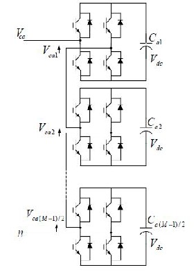
A cascaded multilevel inverter is made up from a series of H-bridge (single-phase full bridge) inverters, each with their own isolated dc bus. This multilevel inverter can generate al- most sinusoidal waveform voltage from several separate dc sources (SDCSs), Figure 2-4 shows a single phase structure of an M-level H-bridges multilevel cascaded inverter. Each level can generate three different voltage outputs +Vdc, 0, -Vdc by connecting the dc sources to the ac output side by different combinations of the four switches.
Figure 2-5 Single Phase Structure of a m-level H-bridges multilevel cas- caded inverter
IJSER © 2011 http://www.ijser.org
International Journal of Scientific & Engineering Research Volume 2, Issue 10, October-2011 3
ISSN 2229-5518
The output voltage of an M-level inverter is the sum of all of the individual inverter outputs. It is clear from Figure 2-5 that to have an M-level cascaded multilevel inverter we need (M-1)/2 H-bridge units in each phase. An example phase vol- tage waveform for a 11-level cascaded multilevel inverter with three dc sources and five full bridges is shown in Figure2-6. The output phase voltage is given by van = va1+va2+va3+va4+va5.
Figure 2-6 Waveforms of the 11-level cascade inverter
3 CONTROL OF CASCADE INVERTER
Fig. 2-6 shows waveforms of the 11-level cascade inverter for var compensation. The output phase voltage VCa-n is the sum of five H-bridge inverter units’ outputs. The phase vol- tage magnitude is controlled by each inverter’s duty cycle. For var compensation, the phase current Ica is always leading or lagging the phase voltage VCa-n by 90. The average charge to each dc capacitor is equal to zero over every half-line cycle for all pulses P1–P5. In other words, the voltage of each dc capaci- tor is always balanced [11], [12]. However, this is not true when the cascade inverter is applied to harmonic filtering. Fig.
6 shows the waveforms, where, for instance, a fifth harmonic current needs to be absorbed by the inverter. In this case, as shown in the figure, an H-bridge inverter unit will be over- charged if it repeats pulse P5 and over discharged if it repeats pulse P4. In order to overcome this problem, swapping pulses every half cycle, as shown in Fig.3-1 , is proposed. As a result, all dc capacitors will be equally charged and balanced
3.1 Voltage Balancing Control
As shown in Fig. 3.1, rotating pulses P1–P5 every half cycle among the five inverter units makes all dc capacitors equally charged and balanced over five half cycles. Therefore, in order to regulate all dc capacitors’ average voltages, only one dc capacitor ’s voltage needs to be monitored and fed back. This feature makes control very simple and reliable. Fig. 3-2 shows the control block diagram of the power line conditioner system. To control all dc capacitors’ voltages, a feedback loop is used. Note that only one dc capacitor ’s voltage is detected.
In Fig. 3-2, a vector phase-locked loop (PLL) is used to get the phase angle of the line terminal voltage. A proportional and integral (PI) controller is employed to regulate the dc ca- pacitors’ voltage. See [11] and [12] for details. In the duty-cycle lookup table, the duty cycle data, θ1– θ5is stored over one fun- damental cycle. Table I shows the phase angles calculated off- line to minimize harmonics for each modulation index (MI). A duty-cycle swapping circuit rotates pulses every half cycle, as shown in Fig. 3-1

Figure 3-1 Waveforms of the 11-level cascade inverter for Harmonic filter- ing.
Figure 3-2 Control Diagram of 11-level cascade Inverter
IJSER © 2011 http://www.ijser.org
International Journal of Scientific & Engineering Research Volume 2, Issue 10, October-2011 4
ISSN 2229-5518
3.2 Required DC Capacitance
From the cascade inverter structure, it is obvious that more capacitance is needed compared with a traditional two-level inverter. For the 11-level cascade inverter to compensate reac- tive power only, it has been shown that 1.36 times of conven- tional var compensator’s capacitance is required. For var and harmonic compensation, all dc capacitors should have an equal capacitance because of pulse rotation among the H- bridge units instead of fixed pulse patterns. In addition, the
required capacitance should be determined in the worst case. From Figs. 2-6 and 3-1, one can see that harmonics have little contribution to the capacitors’ charge because of their higher frequency, but the reactive current may dominate voltage rip- ples of the dc capacitors at the fundamental frequency. There- fore, the required dc capacitance of each capacitor can be ex- pressed as
4 EXPERIMENTAL VERIFICATION
The experimental power line conditioner system uses an
11-level (21 line-to-line level) three-phase cascade inverter. The line voltage is 240 V, power line conditioner rating 10 kVA. The power line conditioner adopts the conventional cur- rent injection method as used in active power filters to com- pensate load harmonics and reactive power.
5 SIMULATION RESULTS
A three phase system with 240V, 50hz circuit has been computed
Discrete,

= 5e-005 powergui
Series RLC Branch 9
A a Series RLC Branch 10
B b
C c
Series RLC Branch 11
m and phase
Phase Error
outputs
Three-Phase
-I Measurement
P N
a phase
P N
b phase
P N
c phase
pulses for a phase
pulses for b phase
pulses for c phase
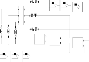
Figure 4-2 Simulink diagram of Single Phase Structure of a 11-level H-
Figure 4-1 Simulink diagram of Cascaded Multipulse Inverter
bridges multilevel cascaded inverter.
IJSER © 2011 http://www.ijser.org
International Journal of Scientific & Engineering Research Volume 2, Issue 10, October-2011 5
ISSN 2229-5518
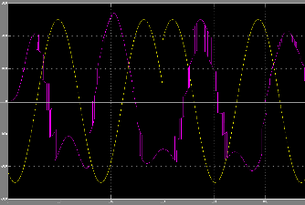
Figure 4-3 Simulation Results of 11-Level CMLI STSTCOM.
Figure 4-4 FFT Analysis of 11-Level CMLI SATACOM.
6 CONCLUSION
The voltage control scheme presented in this paper for cascade multilevel inverter based STATCOM is a simple and effective method for load voltage regulation. Results presented here validate the basic principle of STATCOM for voltage regula- tion applications. Although, in this paper, only single-phase
11- level Cascaded Multilevel Inverter based STATCOM has been employed the same procedure canbe easily extended for a three-phase system.
ACKNOWLEDGMENT
We are thankful to Deaprtment of Electrical and Electronica Engineering of NRI Institute of Technology, Agiripalli and Vikas College of Engineering, Nunna, India with whom we had useful discussions regarding PLC, Multi level Inverter based STATCOM. Any Suggestions for futher improvement of this topic are most welcome
REFERENCES
[1] J. Rodriguez, J.-S. Lai, and F. Z. Peng, “Multilevel inverters: A survey
of topologies, controls, and applications,” IEEE Trans. Ind. Electron., vol.
49, no. 4, pp. 724–738, Aug. 2002.
[2] L. G. Franquelo, J. Rodriguez, J. I. Leon, S. Kouro, R. Portillo, and
M. A. M. Prats, “The age of multilevel converters arrives,” IEEE Ind.
Electron. Mag., vol. 2, no. 2, pp. 28–39, Jun. 2008.
[3] M. F. Escalante and J. J. Arellano, “Harmonics and reactive power com- pensation using a cascaded H-bridge multilevel inverter,” in Proc. IEEE Int. Symp. Ind. Electron., Jul. 2006, vol. 3, pp. 1966–1971.
[4] C. Rech and J. R. Pinheiro, “Hybrid multilevel converters: Unified analy- sis and design considerations,” IEEE Trans. Ind. Electron., vol. 54, no. 2, pp. 1092–1104, Apr. 2007.
[5] M. Marchesoni, “High-performance current control techniques for applica- tions to multilevel high-power voltage source inverters,” IEEE Trans. Power Electron., vol. 7, pp. 189–204, Jan. 1992
Author Profiles

G.G.Rajasekhar obtained his B.E from Karnataka University, India and M.Tech from JNT University, India. He has 11 years experience in teaching. He is pursuing his Ph.D from Acharya Nagarjuna University.
Presently he is a Professor in Electrical and Elec- tronics Engineering Department at Vikas College of Engineering and Technology, Nunna, India. His areas of interests include Power Systems, High Voltage
Engineering and HVDC Transmission etc.Email Id:ggrs73@gmail.com,
PH: 9704082285

N.Sambasiva Rao received the B.Tech degree in Electrical & Electronics Engineering and M. Tech in Electrical Power Engi- neering from JNTU Hydefabad, India.
He has 10 years experience in teaching. He is per- suing his Ph.D from JNTU, Kakinada India.
Presently he is a Associate Professor and Head of the department at NRI Institute of Technology, Agi- ripalli, India. He got “Best Achiever award of Andhra Pradesh “By NCERT, New Delhi, India. His Areas of
interst include Electrical Machines, control Systems and power System
Proteetion e.t.c.Email-Id:samba_rao3@yahoo.com, PH: 9494055169

T.Vijay Muni received the B.Tech degree in Electrical and Electronics Engineering from JNT University, Hyderabad, India in 2007 and M.Tech degree in Power and Industrial Drives from JNT University, Kakinada, India.
After receiving the B.Tech degree, he spent four years with the Department of Electrical and Electron- ics Engineering, Sri Sarathi Institute of Engineering and Technology, Nuzvid, India as Assistant Profes- sor. During this period, he was involved with various
research and development projects. Currently he is a Assistant Professor in NRI Institute of Technology, Agiripalli, India. His research interests include FACTS, Power Electronics and Power System Analysis. Email- Id:www.vijaymuni@gmail.com, PH: 9000055144
IJSER © 2011 http://www.ijser.org