International Journal of Scientific & Engineering Research Volume 3, Issue 3, March -2012 1
ISSN 2229-5518
Implementation of Advanced Encryption Standard
Algorithm
M.Pitchaiah, Philemon Daniel, Praveen
Abstract—Cryptography is the study of mathematical techniques related to aspects of information security such as confidentiality, data integrity, entity authentication and data origin authentication. In data and telecommunications, cryptography is necessary when communicating over any unreliable medium, which includes any network particularly the internet. In this paper, a 128 bit AES encryption and Decryption by using Rijndael algorithm (Advanced Encryption Standard algorithm) is been made into a synthesizable using Verilog code which can be easily implemented on to FPGA. The algorithm is composed of three main parts: cipher, inverse cipher and Key Expansion. Cipher converts data to an unintelligible form called plaintext. Key Expansion generates a Key schedule that is used in cipher and inverse cipher procedure. Cipher and inverse cipher are composed of special number of rounds. For the AES algorithm, the number of rounds to be performed during the execution of the algorithm uses a round function that is composed of four different byte-oriented transformations: Sub Bytes, Shift Rows, Mix columns and Add Round Key.
Index Terms—Advanced Encryption Standard, Cryptography, Decryption, Encryption.
I. INTRODUCTION
THE Cryptography plays an important role in the security of data transmission [1]. This paper addresses efficient hardware implementation of the AES (Advanced Encryption Standard) algorithm and describes the design and performance testing of Rijndael algorithm [3]. A strong focus is placed on high throughput implementations, which are required to support security for current and future high bandwidth applications [5][6][7][8][9]. This implementation will be useful in wireless security like military communication and mobile telephony where there is a gayer emphasis on the speed of
communication [5]. This standard specifies the Rijndael algorithm, a symmetric block cipher that can process data blocks of 128 bits, using cipher keys with lengths of 128,192, and 256 bits [2]. Throughout the remainder of this standard,
the algorithm specified herein will be referred to as ―the AES algorithm.‖ The algorithm may be used with the three different key lengths indicated above, and therefore these different ―flavors‖ may be referred to as ―AES-128‖, ―AES-
192‖, and ―AES-256‖.
A. AES Algorithm
AES is short for Advanced Encryption Standard and is a United States encryption standard defined in Federal Information Processing Standard (FIPS) 192. AES is the most recent of the four current algorithms approved for federal us in the United States. AES is a symmetric encryption algorithm processing data in block of 128 bits. AES is
symmetric since the same key is used for encryption and the reverse transformation, decryption [2]. The only secret necessary to keep for security is the key. AES may configured to use different key-lengths, the standard defines 3 lengths and the resulting algorithms are named AES-128, AES-192 and AES-256 respectively to indicate the length in bits of the key. The older standard, DES or Data Encryption Standard. DES is upto 56bits only [4]. To overcome the disadvantages of des algorithm, the new standard is AES algorithm. This
standard explicitly defines the allowed values for the key length (Nk), block size (Nb), and number of rounds (Nr).
B. AES Algorithm Specification
For the AES algorithm, the length of the input block, the output block and the State is 128 bits. This is represented by Nb = 4, which reflects the number of 32-bit words (number of columns) in the State.
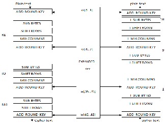
Fig 1: General structure of AES algorithm
An implementation of the AES algorithm shall support at least one of the three key lengths: 128, 192, or 256 bits (i.e., Nk = 4, 6, or 8, respectively). Implementations may optionally support two or three key lengths, which may promote the interoperability of algorithm implementations. For the AES algorithm, the length of the Cipher Key, K, is 128, 192 or 256 bits. The key length is represented by Nk = 4, 6, or 8which reflects the number of 32-bit words (number of columns) in the Cipher Key. For the AES algorithm, the number of rounds to be performed during the execution of the algorithm is dependent on the key size. The number of rounds is represented by Nr, where Nr = 10 when Nk = 4, Nr = 12 when
IJSER © 2012 http://www.ijser.org
International Journal of Scientific & Engineering Research Volume 3, Issue 3, March -2012 2
ISSN 2229-5518
Nk = 6, and Nr = 14 when Nk = 8. The only Key-Block-Round combinations that conform to this standard are given in Table
1.
Bit pattern | Key Length (NK Words) | Block Size (NB Words) | No Of Rounds (NR Words) |
AES- 128 | 4 | 4 | 10 |
AES- 192 | 6 | 4 | 12 |
AES- 256 | 8 | 4 | 14 |
Table 1. Key-Block-Round Combinations.
For both its Cipher and Inverse Cipher, the AES algorithm uses a round function that is composed of four different byte- oriented transformations:
1) Byte substitution using a substitution table (S-box),
2) Shifting rows of the State array by different offsets,
3) Mixing the data within each column of the State array, and
4) Adding a Round Key to the State.
II. ENCRYPTION
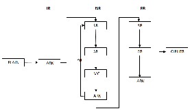
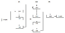
In encryption mode, the initial key is added to the input value at the very beginning, which is called an initial round. This is followed by 9 iterations of a normal round and ends with a slightly modified final round, as one can see in Figure 2. During one normal round the following operations are performed in the following order: Sub Bytes, Shift Rows, Mix Columns, and Add Round key. The final round is a normal round without the Mix Columns stage.
Fig 2: General structure of Encryption.
A. Steps in AES Encryption
Sub Bytes—a non-linear substitution step where each byte is replaced with another according to a lookup table.
Shift Rows—a transposition step where each row of the state is shifted cyclically a certain number of steps.
Mix Columns—a mixing operation which operates on the columns of the state, combining the four bytes in each column
Add Round Key—each byte of the state is combined with the round key; each round key is derived from the cipher key using a key schedule
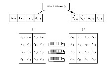
B. Sub bytes Transformation
The Sub Bytes transformation is a non-linear byte substitution that operates independently on each byte of the State using a substitution table (S-box). This S-box which is invertible is constructed by composing two transformations:
1. Take the multiplicative inverse in the finite field GF (28), the element {00} is mapped to itself.
2. Apply the following affine transformation (over GF (2)):
For 0<i<8, where bi is the ith bit of the byte, and ci is the ith bit
of a byte c with the
Value {63} or {01100011}. Here and elsewhere, a prime on a
variable (e.g., b)
Indicates that the variable is to be updated with the value on
the right. In matrix form, the affine transformation element of
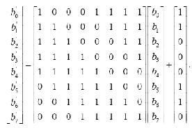
the S-box can be expressed as:
Fig 3: Affine transformation
63 | 7C | 77 | 7B |
CA | 82 | C9 | 7D |
B7 | FD | 93 | 26 |
04 | C7 | 23 | C3 |
Fig 4: S-BOX
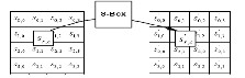
Fig.5 Effect of the Sub Bytes () transformation on the State.
C. Shift Rows Transformation
In the Shift Rows transformation, the bytes in the last three rows of the State are cyclically shifted over different numbers
IJSER © 2012 http://www.ijser.org
International Journal of Scientific & Engineering Research Volume 3, Issue 3, March -2012 3
ISSN 2229-5518
of bytes (offsets). The first row is not shifted at all, the second row is shifted by one the third row by two, and the fourth row by three bytes to the left. Specifically, the Shift Rows
transformation proceeds as follows:
The shift value shift(r,Nb) depends on the row number, r, as
follows (recall that Nb = 4): shift(1,4) 1; shift(2,4) 2 ; shift(3,4) 3
.This has the effect of moving bytes to ―lower‖ positions in the row (i.e., lower values of c in a given row), while the ―lowest‖ bytes wrap around into the ―top‖ of the row (i.e., higher values of c in a given row)
Fig.6 .Shift Rows cyclically shifts the last three rows in the
State.
D. MixColumns Transformation
The Mix Columns transformation operates on the State column-by-column, treating each column as a four-term polynomial.
'
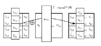
E. Add round Key Transformation
In the Add Round Key transformation, a Round Key is added to the
State by a simple bitwise XOR operation. Each Round Key consists
of Nb words from the key schedule.Those Nb words are each added
into the columns of the State, such that [wi] are the key schedule words, and round is a value in the range 0 round Nr. In the Cipher,
the initial Round Key addition occurs when round = 0, prior to the
first application of the round function. The application of the
Add
Round Key transformation to the Nr rounds of the Cipher
occurs
when 1<round <Nr. The action of this transformation is
illustrated
in Fig. 8, where l = round * Nb.
s0,c
02 03
01 01 s0,c
'
s1,c 01 02 03
01 s1,c
s2,c
01
01 02
03 s2,c
'
s3,c
(0 c < Nb)
03
01 01
02 s3,c
Fig.8. AddRoundKey XORs each column of the State with a word from the key schedule.
As a result of this multiplication, the four bytes in a column are replaced by the following:
S’0,c = ({02} • s0,c) + ({03} • s1,c) + s2,c + s3,c
S’1,c = s0,c + ({02} • s1,c) + ({03} • s2,c) + s3,c
S’2,c = s0,c + s1,c + ({02} • s2,c) + ({03} • s3,c)
S’3,c = ({03} • s0,c) + s1,c + s2,c + ({02} • s3,c)
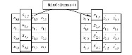
Fig.7. Mix Columns operates on the State column-by-column.
F. Key Expansion
The AES algorithm takes the Cipher Key, K, and performs a Key Expansion routine to generate a key schedule. The Key Expansion generates a total of Nb (Nr + 1) words: the algorithm requires an initial set of Nb words, and each of the Nr rounds requires Nb words of key data. The resulting key schedule consists of a linear array of 4-byte words, denoted [wi ], with i in the range 0 < i < Nb(Nr + 1). The expansion of the input key into the key schedule proceeds according to the pseudo code. SubWord is a function that takes a four-byte input word and applies the S-box to each of the four bytes to produce an output word. The function Rot Word takes a word [a0,a1,a2,a3] as input, performs a cyclic permutation, and returns the word [a1,a2,a3,a0]. The round constant word array, Rcon[i], contains the values given by [xi-1,{00},{00},{00}], with x i-1 being powers of x (x is denoted as {02}) in the field GF(28). The first Nk words of the expanded key are filled with the Cipher Key. Every following word, w[i], is equal to the
IJSER © 2012 http://www.ijser.org
International Journal of Scientific & Engineering Research Volume 3, Issue 3, March -2012 4
ISSN 2229-5518
XOR of the previous word, w[i-1], and the word Nk positions earlier, w[i-Nk]. For words in positions that are a multiple of Nk, a transformation is applied to w[i-1] prior to the XOR, followed by an XOR with a round constant, Rcon[i]. This transformation consists of a cyclic shift of the bytes in a word (RotWord), followed by the application of a table lookup to all four bytes of the word (SubWord). It is important to note that the Key Expansion routine for 256-bit Cipher Keys (Nk = 8) is slightly different than for 128- and 192-bit Cipher Keys. If Nk
= 8 and i-4 is a multiple of Nk, then SubWord () is applied to w
[i-1] prior to the XOR.
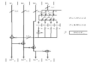
Fig.9.key expansion
III. DECRYPTION
In decryption mode, the operations are in reverse order compared to their order in encryption mode. Thus it starts with an initial round, followed by 9 iterations of an inverse normal round and ends with an AddRoundKey. An inverse normal round consists of the following operations in this order: AddRoundKey, InvMixColumns, InvShiftRows, and InvSubBytes. An initial round is an inverse normal round without the InvMixColumns.
shifted by Nb - shift(r, Nb) bytes, where the shift value
shift(r,Nb) depends on the row number.
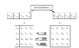
Fig.11.InvShiftRows transformation
B. Inv Subbytes Transformation
InvSubBytes is the inverse of the byte substitution transformation, in which the inverse Sbox is applied to each byte of the State. This is obtained by applying the inverse of the affine transformation followed by taking the multiplicative inverse in GF (28).The inverse S-box used in the InvSubBytes () transformation is presented in Fig 12.
52 | 09 | 6A | D5 |
7C | E3 | 39 | 82 |
54 | 7B | 94 | 32 |
08 | 2E | A1 | 66 |
Fig 12: Inverse S-BOX
C. Inv MixColumns Transformation
InvMixColumns is the inverse of the MixColumns transformation. InvMixColumns operates on the State column-by-column, treating each column as a four term polynomial. The columns are considered as polynomials over GF (28) and multiplied modulo x4 + 1 with a fixed polynomial a-1(x), given by a-1(x) = {0b} x3 + {0d} x2 + {09} x + {0e}, this can be written as a matrix multiplication. Let
As a result of this multiplication, the four bytes in a column are replaced by the following:
'
0,c
0e
0b 0d
09 s0,c
'
s1,c 09 0e
0b 0d s1,c
'
2,c
0d
09 0e
0b s2,c
'
Fig 10: General structure of Decryption.
A. Inv Shift rows Transformation
s3,c
0b 0d
09 0e s3,c
InvShiftRows is the inverse of the ShiftRows transformation. The bytes in the last three rows of the State are cyclically
S’0,c = ({0e} • s0,c) + ({0b} • s1,c) + ({0d} • s2,c) + ({09} •
s3,c)
shifted over different numbers of bytes (offsets). The first row,
r = 0, is not shifted. The bottom three rows are cyclically
S’
1,c
= ({09} • s
0,c
) + ({0e} • s
1,c) + ({0b} • s
2,c
) + ({0d} •
IJSER © 2012 http://www.ijser.org
International Journal of Scientific & Engineering Research Volume 3, Issue 3, March -2012 5
ISSN 2229-5518
s3,c)
S’2,c = ({0d} • s0,c) + ({09} • s1,c) + ({0e} • s2,c) + ({0b} •
s3,c)
S’3,c = ({0b} • s0,c) + ({0d} • s1,c) + ({09} • s2,c) + ({0e} •
s3,c)
D. Inverse of the Addroundkey Transformation
AddRoundKey is its own inverse, since it only involves an application of the XOR operation. Equivalent Inverse Cipher transformations differ from that of the Cipher, while the form of the key schedules for encryption and decryption remains the same. However, several properties of the AES algorithm allow for an Equivalent Inverse Cipher that has the same sequence of transformations as the Cipher (with the transformations replaced by their inverses). This is accomplished with a change in the key schedule. The two properties that allow for this Equivalent Inverse Cipher are as follows: The Sub Bytes and Shift Rows transformations commute; that is, a Sub Bytes transformation immediately followed by a Shift Rows transformation is equivalent to a Shift Rows transformation immediately followed by a Sub Bytes transformation.
The same is true for their inverses, InvSubBytes and InvShiftRows. The column mixing operations - MixColumns and InvMixColumns – are linear with respect to the column input, which means Inv MixColumns(state XOR Round Key)
=InvMixColumns(state)XORInvMixColumns(RoundKey).The se properties allow the order of InvSubBytes and InvShiftRows transformations to be reversed. The order of the AddRoundKey and InvMixColumns transformations can also be reversed, provided that the columns (words) of the decryption key schedule are modified using the InvMixColumns transformation. The equivalent inverse cipher is defined by reversing the order of the InvSubBytes and InvShiftRows transformations and by reversing the order of the AddRoundKey and InvMixColumns transformations
used in the ―round loop‖ after first modifying the decryption key schedule for round = 1 to Nr-1 using the InvMixColumns transformation. The first and last Nb words of the decryption key schedule shall not be modified in this manner.
IV. IMPLEMENTATION RESULTS AND DISCUSSION
This paper was successfully completed with the implementation of Encryption and decryption for AES algorithm. We implemented different sub modules for AES algorithm by using Verilog code. This implementation will be useful in wireless security like military communication and mobile telephony where there is a gayer emphasis on the speed of communication.
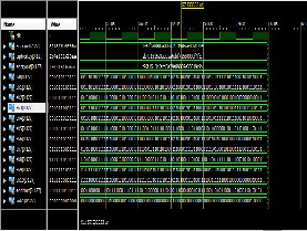
Fig 13.Encryption Result
Encryption simulation was successfully completed by the use of key expansion and transformations of shift Rows, sub bytes, mix columns, add round keys.
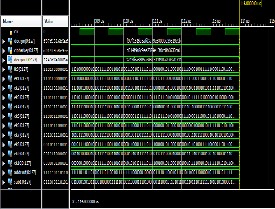
Fig 14.Decryption Result
Decryption simulation was successfully completed by the use of key expansion and transformations of inverse shift Rows, inverse sub bytes, inverse mix columns, inverse add round keys.
V. CONCLUSION AND FUTURE WORK
This paper was successfully completed with the implementation of AES algorithm on 128 bit message. The encrypted cipher text and the decrypted text are analyzed and proved to be correct. The encryption efficiency of the proposed AES algorithm was studied and met with satisfactory results. The following can be considered for the future works of this paper:
An extra modification to be used for 192 bit and
256 bit key AES which is an extension of the
present paper.
IJSER © 2012 http://www.ijser.org
International Journal of Scientific & Engineering Research Volume 3, Issue 3, March -2012 6
ISSN 2229-5518
Power reduction and area minimization for the proposed AES algorithm is to be device.
LCD can be used for display.
VI. AES APPLICATIONS
AES Encryption and Decryption has many applications. It is used in cases where data is too sensitive that only the authorized people are supposed to know and not to the rest. The following are the various applications
Secure Communication
- Smart Cards
- RFID.
- ATM networks.
- Image encryption
Secure Storage
- Confidential Cooperate Documents
- Government Documents
- FBI Files
- Personal Storage Devices
- Person Information Protection
REFERENCES
[1] A. Lee, NIST Special Publication 800-21, Guideline for
Implementing Cryptography in the Federal Government,
National Institute of Standards and Technology, November 1999.
[2] J. Daemen and V. Rijmen, The block cipher Rijndael, Smart Card research and Applications, LNCS 1820, Springer- Verlag, pp. 288-296.
[3] J. Nechvatal, et. al., Report on the Development of the Advanced Encryption Standard (AES), National Institute of Standards and Technology, October 2, 2000.
[4] ―Specification for the Advanced Encryption Standard (AES),‖ Federal Information Processing Standards Publication 197, Nov. 2001
[5] A. Menezes, P. van Oorschot, and S. Vanstone, Handbook
of Applied Cryptography, CRC Press, New York, 1997, p.
81-83.
[6] C.-P. Su, T.-F. Lin, C.-T. Huang, and C.-W. Wu, ―A high-
throughput low-cost AES processor,‖ IEEE Commun. Mag., vol. 41, no. 12, pp.86–91, Dec. 2003.
[7] C.-P. Su, C.-L. Horng, C.-T. Huang, and C.-W. Wu, ―A
configurable AES processor for enhanced security,‖ in
Proc. ASP-DAC, Shanghai, China, Jan. 2005, pp. 361–366.
[8] Rachh, R.R.; Anami, B.S.; Ananda Mohan, P.V. ―Efficient
implementations of S-box and inverse S-box for AES
algorithm,‖ in TENCON 2009 - 2009 IEEE Region 10

Conference , Nov. 2009, pp. 1–6.
[9] Kaur, Swinder; Vig, Renu , ‖ Efficient Implementation of AES Algorithm in FPGA Device‖ in Conference on Computational Intelligence and Multimedia Applications, Nov 2007,pp. 179-187
IJSER © 2012 http://www.ijser.org