
International Journal of Scientific & Engineering Research, Volume 5, Issue 7, July-2014 1139
ISSN 2229-5518
Amar Mandekar1, S.D. Patil2, D.S. Arora3
1.(M.E Student, Department of Electronics &Telecommunication, Rajiv Gandhi Institute of Tech., Mumbai University India ) (amar.mandeka@yahoo.com)
2.(Asst. Professor, Department of Electronics &Telecommunication, Rajiv Gandhi Institute of Tech., Mumbai University India ) (sdpatil65@rediffmail.com)
3.(Asst. Professor, Department of Electronics &Telecommunication, Rajiv Gandhi Institute of Tech., Mumbai University India ) (dsvgupta@gmail.com)
Abstract: - Multiple-input multiple-output (MIMO) wireless technology in combination with Orthogonal frequency division multiplexing (MIMO-OFDM) is an attractive air-interface solution for next-generation wireless local area networks (W LANs), wireless metropolitan area networks (W MANs), and fourth- generation mobile cellular wireless systems. This paper first focuses on 802.11n standard, MIMO-OFDM system. This paper focuses on high level Matlab Simulink 4 x 4 spatially multiplexed (SM) MIMO OFDM transceiver encoded at ½ rate using 64 size FFT which is designed and implemented on Spartan Virtex 6 FPGA board.
Index terms: Field Programmable Gate Array, Multiple Input Multiple Output, Matlab Simulink, Orthogonal Frequency Division Multiplexing, Spatial
Multiplexing, Space Time Block Code, System Generator and Xilinx.
—————————— ——————————
The key challenge faced by future wireless communication systems is to provide high-data-rate wireless access at high quality of service (QoS). The best approach for real time application to achieve high throughput and network capacity for fourth generation wireless local area networks is to combine MIMO wireless technology with OFDM. With increasing demand of higher data rate for telecommunication, the IEEE802.11n standard was constituted in 2009. The most important character of the standard is MIMO-OFDM, which not only improves the throughput but also the spectrum efficiency and channel capacity.One of the techniques being Orthogonal Frequency Division Multiplexing (OFDM), which offers reliable high bit rate wireless system with reasonable low complexity. OFDM is a combination of modulation and multiplexing and are able to maximize spectral efficiency without causing adjacent channel interference. OFDM does provide large data rates with sufficient robustness to radio channel impairments.
The new 802.11n standard is predicted to be capable of supporting data rates up to 600 Mbps [1] by deploying the latest communication method such as "MIMO" (Multiple Input Multiple Output). The MIMO operations are based on STBC (Space Time Block Code) and SM (Spatial Multiplexing). The STBC method helps in enhancing Quality of Service (QoS) of the system whereas SM method
leads to result in higher capacity in the system. The data rate can only be achieved if it is efficiently realized in real hardware design. There are several methods to implement the MIMO-OFDM system like ASIC, microprocessors and microcontrollers and FPGA. The implementation on FPGA is better than on a general purpose MPU in terms of speed and on ASIC in terms of cost.
The goal of this article is to implement a 4x4 MIMO OFDM
baseband transceiver by using 16-QAM at the code rate of
½ and Spatial Multiplexing on an FPGA with reasonable
prices of hardware implementation and achieve data rate
216 Mbps.
Outline: The remainder of this paper is structured as follows: An overview of the MIMO-OFDM system under consideration is presented in Section II. The next section contains a brief introduction into MIMOwire-less and OFDM. Section VI. explains 4X4 MIMO-OFDM system level design. Methodology for design and implementation is discussed in section V. It is followed by a summary of recent results on the implementation of a four-stream spatial-multiplexing MIMO-OFDM transceiver. Finally, we provide relevant open areas for further research and conclusion.
IJSER © 2014 http://www.ijser.org
International Journal of Scientific & Engineering Research, Volume 5, Issue 7, July-2014 1140
ISSN 2229-5518
The overall system is split into two main parts: the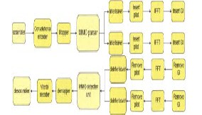
transmitter and the receiver. The figure 2.1 shows the block diagram of 802.11n system
Fig. 2.1 Block diagram of 802.11n system
The scrambler transposes or inverts signal s or otherwise encodes a message at the transmitter to make the message unintelligible at a receiver. The data bits are encoded using a convolutional encoder. Convolutional encoding with Viterbi decoding is a FEC technique that is particularly suited to a channel in which the transmitted signal is corrupted mainly by additive white Gaussian noise.
According to the modes of operation the data bits are
punctured and mapped with QPSK constellations mentioned as per the standard. Puncturing is the process of removing some of the parity bits. The MIMO parser performs different operations on input data bits. This operation is based on Space Time Coding (STC) or Spatial Multiplexing (SM). Among the most important STC’s are the Alamouti and trellis codes. The D-BLAST and V-BLAST methods are among the most important methods in Spatial Multiplexing.
The interleaver thereby interleaves the bits which
correspond to spatial data stream by performing multiple column rotation to increase diversity of the wireless system. By Insert Pilot it is possible to prevent Inter carrier interface (ICI). The IFFT block transforms frequency signal into time domain.
Multiple-Input-Multiple-Output (MIMO) antenna systems provide higher data rates up to 100Mbps. The combination of OFDM with MIMO results in less BER and improved Eb/No.
At the receiver the blocks operation depends on the method
used to code the signal in transmitter. The signal should first be detected and it is sent to FFT block. After calculation FFT, the signals are deinterleaved and sent to the MIMO Detection unit. The detected signals are then decoded using a viterbi decoder and finally descrambled at the receiver end.
Multiple-input multiple-output (MIMO) wireless technology in combination with Orthogonal frequency division multiplexing (MIMO-OFDM) is an attractive airinterface solution for next-generation wireless local area networks (WLANs), wireless metropolitan area networks (WMANs), and fourth-generation mobile cellular wireless systems.
In MIMO, the system exploits the fact that the received signal from one transmit antenna can be quite different than the received signal from a second antenna. This is most common in indoor or dense metropolitan areas where there are many reflections and multipath between transmitter and receiver [9]. In this case, a different signal can be transmitted from each antenna at the same frequency and still be recovered at the receiver by signal processing.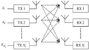
Fig..3.1 Transmit 2 Receive (2x2) MIMO channel
Spatial Multiplexing (SM) is a technology that significantly increases the bit rate in a wireless radio link by exploiting multiple antennae at both the CPE and BS, without any additional power or bandwidth. SM also offers a linear increase in spectrum efficiency under specific conditions.
In Fig. 3.2, a high-rate bit stream (left) is decomposed into three independent 1/3-rate bit sequences which are then transmitted simultaneously using multiple antennas, thus consuming one third of the nominal spectrum. The signals are launched and naturally mix together in the wireless channel as they use the same frequency spectrum [4][10].
IJSER © 2014 http://www.ijser.org
International Journal of Scientific & Engineering Research, Volume 5, Issue 7, July-2014 1141
ISSN 2229-5518
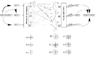
Fig.3.2 Basic spatial multiplexing scheme with three
Transmitter and three Receiver antennas
At the receiver, after having identified the mixing channel matrix through training symbols, the individual bit streams are separated and estimated [9]. This occurs in the same way as three unknowns are resolved from a linear system of three equations. This assumes that each pair of transmit receive antennas yields a single scalar channel coefficient, hence flat fading conditions.
The separation is possible only if the equations are independent which can be interpreted by each antenna “seeing” a sufficiently different channel in which case the bit streams can be detected and merged together to yield the original high rate signal.
Orthogonal Frequency Division Multiplexing (OFDM) is a combination of modulation and multiplexing. In this technique, the given bandwidth is shared among individual modulated data sources. Normal modulation techniques like AM, PM, FM, BPSK, QPSK, etc... are single carrier modulation techniques, in which the incoming information is modulated over a single carrier [1].
OFDM is a multicarrier modulation technique, which employs several carriers, within the allocated bandwidth, to convey the information from source to destination. Each carrier may employ one of the several available digital modulation techniques like BPSK, QPSK, and QAM.
A communications data stream is effectively split into N parallel low bandwidth modulated data streams. Each sub- carrier overlaps, but they are all orthogonal to each other, such that they do not interfere with one another. Each of the sub-carriers has a low symbol rate. But the combination of sub-carriers carrying information in parallel allows for high data rates. The other advantage of a low symbol rate is that inter-symbol interference (ISI) can be reduced
dramatically since the symbol time represents a very small proportion of the typical multipath delay [1].
At first system level design is developed by using high level mathematical Modeling software that is Matlab Simulink. This software is chosen because of its modular and real time environment which resembles our real world design. The system level design is split into two parts: the transmitter and receiver.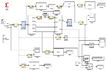
Fig. 4.1. Top Level Design of a 4 x 4 MIMO model
The figure 4.1 represents the 4 x 4 MIMO model. 4 x 4 means there are four transmitters and four receivers. A real time audio signal is provided as input by connecting the Gateway In to the workspace with the help of a manual switch. The Gateway In block is required to convert input which is of Simulink type to Xilinx type. The input sampled voice signal is then fed to the parallel to serial convertor and then is applied to the Subsystem.
The subsystem is the transmitter module while subsystem 1 is the receiver module. The Gateways are used to convert Xilinx type to Simulink type output or vice versa. At the end a scope is connected where the first plot is for output of
4 x 4 MIMO model whereas the second plot is just the input
signal applied to the model. The use of this is to verify
whether the same signal is reproduced at the receiver side. A SNR of 15 dB is added in one of the channel to see the behavior. Displays, scopes are connected to get the readings and observe the signals at different points to get more clear idea of functioning of the entire system.
In order to observe the output of serial to parallel convertor block and actual input they are applied as third and fourth
IJSER © 2014 http://www.ijser.org
International Journal of Scientific & Engineering Research, Volume 5, Issue 7, July-2014 1142
ISSN 2229-5518
input to the scope respectively. The Gateway Out is used to convert the Xilinx type inputs to the Simulink type outputs.
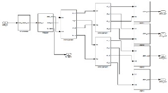
Fig 4.2 The Transmitter Module
. 4.2 The MIMO Receiver Subsystem1
In receiver subsystem as shown in figure 3.4 the outputs of four streams from transmitter are fed as input to OFDM blocks. In ofdm1 FFT performs the exact reverse operation as that of the IFFT. It removes the pilot and guard subcarriers and extracts the ROM_Imag and ROM_Real inputs for mimodeparser. The ofdm 2 block performs exactly same as that of ofdm 1 block and extracts the ROM_Imag and ROM_Real inputs for MIMO deparser. The OFDM 3 and 4 performs exact same as that of OFDM 1 and
2 respectively to be fed as inputs for MIMO deparser 1.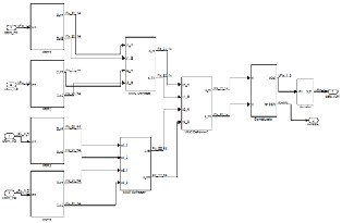
Fig. 4.3 The Receiver Module
The first stage was verification of each block using matlab. The Matlab is multi-purpose software which is usually used for mathematical computation in the engineering
field. After the algorithm is verified, the hardware implementation is obtained by constructing block diagram in Simulink [7]. Then a VHDL code is imported into Simulink via Xilinx system generator block set which will create bit true and cycle accurate hardware model. Figure
5.1 shows the methodology and flow diagram of how
exactly research has carried out.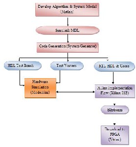
Fig. 5.1 Methodology and Flow Diagram
VI. RESULTS AND DISCUSSION
The main of this paper is implementing a 4 x 4 MIMO OFDM model and to achieve higher data rates. Data rates up to 216 Mbps have been achieved. The hardware co- simulation, RTL Schematics, Test Bench and VHDL codes, are also obtained for the implemented 4 X 4 MIMO OFDM model to verify the same.
Fs and Ts variables appear at the Matlab workspace. Fs and Ts are the sampling frequency and Sample period at the input side respectively. Sampling rate at the transmitter side can be changed by using these two parameters as shown below.
IJSER © 2014 http://www.ijser.org
International Journal of Scientific & Engineering Research, Volume 5, Issue 7, July-2014 1143
ISSN 2229-5518
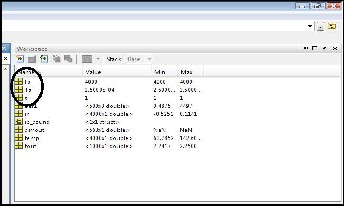
Fig. 6.1 Fs and Ts values in Matlab Workspace
At the input, by default the sampling frequency is 4KHz as shown in workspace and Sample period is Ts = 1/Fs
The data rate at the transmitter can be seen with the help of sample time block as shown below.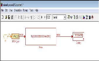
Fig. 6.2 Ts display on probe in Sample Time Block
The sample time at the transmitter as shown in Figure 6.3 is Ts = 8.333333334e-006. The sampling frequency at the transmitter is Fs = 1/Ts = 1/8.333334e-006 = 0.1 MHz i.e.
0.1Mbps. The transmitter data rate can be probed by sample time block. It is as shown below.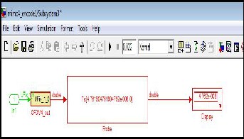
Fig. 6.3 Changed Ts value in probe of Sample Time Block
Ts = 4.762e-008 now,Fs = 1/Ts = 1/4.762e-008 = 21e006 = 21
MHz so, the data rate becomes 21Mbps.
Similarly Fs can be changed to various frequencies and data rate can be achieved to 54 *4 = 216 Mbps. The list of Input sampling frequencies to change transmitter sampling frequencies and achieved data rates between 84 to 216
Mbps are as shown below.
Sr. No. | Input Sampling Freq. Fs | Transmitter Sampling Freq. | Data Rate |
1 | 700 KHz | 21 MHz | 84 Mbps |
2 | 840 KHz | 25 MHz | 100 Mbps |
3 | 980 KHz | 29 MHz | 116 Mbps |
4 | 1.120 MHz | 33 MHz | 132 Mbps |
5 | 1.3 MHz | 39 MHz | 156 Mbps |
6 | 1.5 MHz | 45 MHz | 135 Mbps |
7 | 1.7 MHz | 51 MHz | 204 Mbps |
8 | 1.8 MHz | 54 MHz | 216 Mbps |
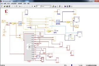
Fig.6.4 Data Rate Display
IJSER © 2014 http://www.ijser.org
International Journal of Scientific & Engineering Research, Volume 5, Issue 7, July-2014 1144
ISSN 2229-5518
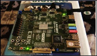
The DONE LED glows indicating that the FPGA is now ready to be programmed.
Fig.6.5 FPGA ready for programming
The output of the scope can be seen in the Figure 6.8 where the first waveform is the signal which has been achieved at the output of model i.e. received signal and the second waveform is the actual signal which was been fed as input to the model.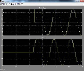
Fig 6.6 Received and Original Signal
6.3 Graphs Plotted
The BER verses SNR calculations are made from the model and checked with different SNR.
Fig 6.7 SNR verses BER
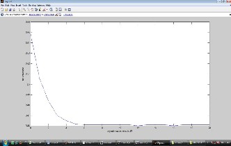
The data rate versus SNR graph is plotted according to model run on the virtex6 board.
Fig. 6.8 Data Rate verses SNR
VI. TRACK FOR FUTURE SCOPE
Development of An 8 X 8 spatially multiplexed MIMO OFDM on similar methodology would be interesting. Different modulation techniques such as QPSK or QAM with subcarriers as 1024 or up to 4096 can be experimentally tried to achieve data rates in multiple of 100
Mbps or more. PAPR greater than 3 dB or more can be achieved for various types of fading channels such as AWGN or Rayleigh channel. Emphasis on performance of Signal to Noise Ratio, Bit Error Rate is possible.
VII .CONCLUSION
MIMO OFDM systems are the answer to our ever increasing data rate needs. By implementing a MIMO
IJSER © 2014 http://www.ijser.org
International Journal of Scientific & Engineering Research, Volume 5, Issue 7, July-2014 1145
ISSN 2229-5518
OFDM baseband transceiver on an FPGA by proper
selection of one of the sixteen configurations the need for high-speed data transmission for a wireless communication system with reasonable prices of hardware implementation is fulfilled.
To conclude, this paper gives the detail knowledge of implementing a 4 X 4 MIMO OFDM transceiver on hardware with use of Matlab Simulink 2010, Xilinx 12.3, Modelsim 6.5 and Digilent Atlys Spartan 6 FPGA board. It can be concluded that, by implementing 4 X 4 MIMO OFDM model the data rate achieved is up to 216 Mbps, which further can be increased by changing the input frequency.
Xilinx System Generator combined with Matlab Simulink provides an easier and efficient way of developing the FPGA system design and simulating it. Also the hardware co-simulation feature of the software enables easier way to test and debug the design effectively on the actual hardware.
Our thanks to the experts who have contributed towards development of the MIMO-OFDM.
[1] Zoha Pajoudi, et. al., “Hardware Implementation of a
802.11n MIMO OFDM Transceiver, “in IEEE Jour.
978-1-4244-2750-5. (2008), 414-419.
[2] Xin Xu, “IEEE 802.11n MIMO Modeling and Channel Estimation Implementation” Tekniska Högskolan Linköpings Universitet,2012.
[3] Simon Haene,David Perels and Andreas Burg, “A Real- Time 4-Stream MIMO-OFDM Transceiver: System Design, FPGA Implementation, and Characterization”, IEEE Journal, VOL. 26, NO. 6, (2008),877-889.
[4] Richard Van Nee, et. al., “The 802.11n MIMO-OFDM Standard for Wireless LAN and Beyond”, Wireless Personal Communications (2006) 37: 445–453.
[5] Helmut Bölcskei, Eth Zurich, “MIMO-OFDM Wireless Systems:Basics, Perspectives, And Challenges MIMO- OFDM Wireless Systems:Basics, Perspectives, And Challenges”, IEEE Wireless Communications, ( August
2006)), 31-37.
6] The University of Adelaide, WLAN Background, available:
http://www.eleceng.adelaide.edu.au/research/undergrad-
projects/archive/WLAN-o ptimisation/ProjectOverview/WLANBackground.htm.
[7] Perahia, E. , “IEEE 802.11n Development:History, Process, and Technology”, Communications Magazine, IEEE, pp. 48-55, July 2008![]()
[8] Yu Wei Lin Chen Yi Lin, “Design of FFT/IFFT Processor for MIMO OFDM Systems,” IEEE Transaction on
circuit and system, Vo1.54, no. 4 pp. 807-815, 2007.
[9] K. F. Lee, et. al., "A space-frequency transmitter diversity technique for OFDM systems," in Proc. Globecom 03, San Francisco, USA, vol.3, pp.24-28, 2003.
[10] D. Getsberg, et. al., " From theory to practice: An overview of MIMO space-time coded wireless systems," in IEEE Jour. Sel. Areas in Commun.,vo1.21, no. 38 pp. 281-301, 2003.
[11] Yin, Hujun of Intel Corporation, “OFDMA : A Broadband Wireless Access Technology,” in IEEE Sarnoff Symposium 2006.
[12] V.R Balaji, et. al., “Design and Implementation of MIMO-OFDM for 4G Mobile Communications”, Journal of Global Reserch in Computer Science, Vol.4, no.1 pp.18-21, 2013.
[13] Parvathi C, et. al., “Fading, Coding And Mimo-Ofdm: A Short Review”, International Journal of Recent Advances in Engineering & Technology (IJRAET), ISSN (Online): 2347 - 2812, Vol.-1, Issue - 1, pp. 69-72,
2013
IJSER © 2014 http://www.ijser.org