International Journal of Scientific & Engineering Research, Volume 3, Issue 11, November-2012 1
ISSN 2229-5518
INVESTIGATION OF HANDOVER IN WCDMA
1Gagandeep
,Department of Electronics & Communication Engineering gdbeniwal88@gmail.com,
N.C. college of Engineering, Panipat
Department of Electronics & Communication Engineering
ABSTRACT—Third generation wireless system is based on the WCDMA access technique. In this technique, all users share the same bandwidth simultaneously but with different codes. So in Soft Handoff (WCDMA) new user will demand new OVSF codes. This behavior effectively reduces the total number of available OVSF codes in each cell. The effective available OVSF codes in each cell decreases as the percentage of calls in soft handover increases. Due to their blocking property these codes cannot be used efficiently. So this paper presents a new non- orthogonal variable spreading factor (NOVSF) codes to support a quite large number code candidates for more user used in multi-rate next-generation wireless system.
Keywords—WCDMA; UMTS; DS-CDMA; Soft Handoff; OVSF Codes; NOVSF Codes; Code Blocking;
I INTRODUCTION
The third generation (3G) wireless standards UMTS/IMT-
2000 use the wideband CDMA (WCDMA) to support high data rate and variable bit rate services with different quality of service (QoS) requirements. In WCDMA, all users share the same carrier under the direct sequence CDMA (DS- CDMA) principle [1]. In the 3GPP specifications, orthogonal variable spreading factor (OVSF) codes are used as channelization codes for data spreading on both downlink and uplink. OVSF codes also determine the data rates allocated to calls. Because OVSF codes require a single RAKE combiner at the receiver, they are preferable to multiples of orthogonal constant spreading factor (SF) codes which need multiple RAKE combiners at the receiver.
When a particular code is used in OVSF, its descendant and ancestor codes cannot be used simultaneously because their encoded sequences become indistinguishable. Therefore, the OVSF code tree has a limited number of available codes. Because one OVSF code tree, along with one scrambling code, is used for transmissions from a single source that may be a base station or mobile station, the same OVSF code tree is used for the downlink transmissions and therefore the base station must carefully assign the OVSF codes to the downlink transmissions. The asynchronous uplink transmissions do not suffer from this limitation since each mobile station as a single source uses a unique scrambling code with the spreading codes of its OVSF code tree, where scrambling code makes signals from different mobile stations separable from each other. But, if the uplink is synchronous, the OVSF code limitations of the
downlink are also valid for the uplink. The use of OVSF codes in downlink and synchronous uplink guarantees that there is no intra-cell interference in a flat fading channel. Since the maximum number of OVSF codes is hard-limited, the efficient assignment of OVSF codes has a significant impact on resource utilization.
Any two OVSF codes are orthogonal if and only if one of them is not a parent code of the other. Therefore, when an OVSF code is assigned, it blocks its entire ancestor and descendant codes from assignment because they are not orthogonal. This results in a major drawback of OVSF codes, called blocking property: a new call cannot be supported because there is no available free code with the requested SF, even if the network has excess capacity to support it. To alleviate the effects of the blocking property of OVSF codes, various schemes such as code reassignment schemes, time sharing of channels, and statistical multiplexing of busty data traffic are proposed in the literature.
This paper presents non-blocking OVSF (NOVSF) codes. NOVSF codes are non-blocking in the sense that no code assignment blocks the assignment of any other code. All NOVSF codes are orthogonal to each other and, therefore, can be assigned simultaneously as far as orthogonality is concerned.
2 UMTS MODEL & OVSF CODES A) umts code allocation scheme
IJSER © 2012 http://www.ijser.org
International Journal of Scientific & Engineering Research, Volume 3, Issue 11, November-2012 2
ISSN 2229-5518
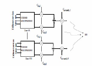
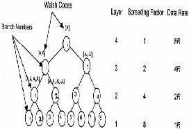
Figure 1 depicts the UMTS code allocation in a cell where every user can transmit his data in one or several channels after multiplying each channel by an orthogonal code. We sum all these channels to constitute the data flow that is multiplied by the unique scrambling code assigned to the user by the base station.
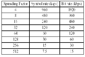
Fig. 2.1.The NOVSF code tree containing eight orthogonal OVSF codes with SF=8 each. Each of these eight codes has 64 time slots.
Fig 1: UMTS System model.
In Fig 1.Each user transmits on a unique scrambling code. All services (voice, data or both) are multiplexed on the scrambling sequence by using separate OVSF codes.
B) ovsf code generation and blocking property
The WCDMA standard defines an 8-layer OVSF code tree in the forward link. The SF from layers 1 to 8 are 512, 256,
128, 64, 32, 16, 8, and 4, respectively. The corresponding data rates handled are R, 2R, 4R, 8R, 16R, 32R, 64R and
128R (where R is the basic data rate 7.5 kbps). The OVSF code tree is generated using the Walsh code procedure explained in Ref. 7. For input code A the two children are [A, A] and [A,–A]. In the second step assume [A, A] as B and [A,–A] as C. The code B and C further generate children
{[B, B], [B,–B]} and {[C, C], [C,–C]}, respectively.
The procedure is repeated eight times to generate 8 layer OVSF code tree as in WCDMA system. Figure 1 shows an OVSF code tree with the SF varying from 1 to 8. It can handle four different data rates R, 2R, 4R and 8R. As explained earlier, in the OVSF scheme a code can be given to the coming user if, all descendents and ancestors of the code from root to leaf is free.
Accordingly, only one code can be assigned to a UE in the path from the root to leaf. The code with the relatively smaller SF is used for user with relatively higher data rate, so that the overall bandwidth  is same.
Table1.1 summarizes the spreading factors, symbol rates, and bit rates for WCDMA physical channels. The spreading factor 512 is used on the downlink only. The chip rate for all spreading factors is
3.84 Mcps
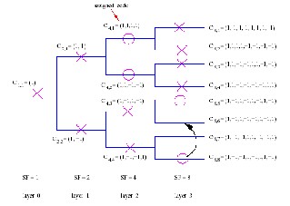
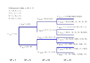
Fig 2.2 Code blocking and reassignment in OVSF
code tree.
IJSER © 2012 http://www.ijser.org
International Journal of Scientific & Engineering Research, Volume 3, Issue 11, November-2012 3
ISSN 2229-5518
Fig 2.2 show the assignment of code C4; 1 shown in Fig.2.1Fig. 3.1.NOVSF codes with four initial orthogonal codes. blocks the assignment of its ancestor codes (i.e., C2;1 and
C1;1) and descendant codes(i.e., C8;1 and C8;2). The circle and cross signs on the links indicate the assigned and blocked codes, respectively
To alleviate code-blocking problem and improve the utilization of OVSF codes, code various schemes such as code reassignment schemes, time sharing of channels and statistical multiplexing of bursty data traffic are proposed. These heuristic algorithms often lead to chain of code reassignments that result in a lot of overhead because many receivers need to be informed of new code reassignments.
3 NON-BLOCKING OVSF CODES
The basic ideas behind the proposed NOVSF codes are discussed next by describing four different cases. In every case, all the codes are orthogonal to each other. They dif- fer from each other in the range of SF and whether time multiplexing is applied.
Technique 1: NOVSF codes with four initial orthogonal codes.
In this case, as shown in Fig. 3.1, there are initially four orthogonal codes, namely, A, B, C, and D. Using these four orthogonal codes, a binary code tree is constructed as follows. Code Ais made the root code with SF=4 in the layer
1 of the tree. For the tree layer 2, the following two orthogonal codes with SF=8 are generated from code B: (B,B) and (B,−B). Similarly, four codes are generated from code C and are placed on layer 3 of the tree. Finally, eight generated codes from D are placed on layer 4 of the tree. All the codes of the tree are orthogonal to each other and, they can be very desirable codes for broadband fixed wireless networks where maximum SF should not exceed 32. Indeed, what is required is to have a code tree of four layers in this case, but the SF of codes at any one of these four layers can be equal to any power of 2 ranging between 4 and 512, depending on the requested data rates of users. For instance, the SFs of the code tree could be 16, 4, 32, and 64 at some instant of time.
In this figure, it is assumed that SF ranges from 4 to
32. But, SF can indeed range from 4 to 512. For instance, the SFs of the tree layers may be 4, 8, 32, and 128
Technique 2: NOVSF codes with eight initial orthogonal codes with SF from 8 to 512.
In this case, as shown in Fig. 3.2, there are initially eight orthogonal codes, namely, A, B, C, D, E, F, G, and H. Using the first seven orthogonal codes, a binary code tree is constructed as follows. Code A is made the root code with SF=8 in the layer 1 of the tree. For the tree layer 2, the following two orthogonal codes with SF= with SF=16 are generated from code B: (B,B) and (B,−B). Similarly, four codes four codes are generated from code C and are placed on layer 3 of the tree. As illustrated in Fig. 3.2 codes D, E, F, and G generate 8, 16, 32, and 64 codes, respectively, and are placed on layers
4, 5, 6, and 7, respectively. Code H can be used as a standby code in any tree layer whenever more codes are needed. Indeed, each one of the eight codes A, B, C, D, E, F, G, and H can have any SF depending on the requested data rates.
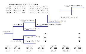
Fig. 3.2.The binary code tree for NOVSF codes with
8≤SF≤512. Only one NOVSF code is illustrated in
layers 4–7 due to space limitations.
Technique 3: NOVSF codes with SF=4 employing time multiplexing
In this case, as shown in Figure 3.3 there are initially four orthogonal codes of SF =4, namely, A, B, C, and D. Each code is associated with a time-slot number and cycle length, in addition to the SF of the code. Cycle-length is simply the sum of the time slots in a cycle. The time-slot number is the label of the time slot in a cycle. When a code is not shared in time, its cycle-length becomes equal to one. Thus, a code is
IJSER © 2012 http://www.ijser.org
International Journal of Scientific & Engineering Research, Volume 3, Issue 11, November-2012 4
ISSN 2229-5518
assigned to a communication channel along with its time-slot and cycle-length. There are mainly two reasons why a code may be shared in time. One
reason is to have better utilization of codes, which leads to an improvement in spectral efficiency of
WCDMA. Another reason to share a code in time is to help rate matching techniques such as repetition or puncturing to achieve the requested data rates. Note that repetition or puncturing is used to adjust the channel-coding rate of each transport channel to match the coded bit rates to one of a limited set of rates on the physical channel.
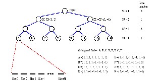
Figure 3.3 The NOVSF code-tree containing eight
orthogonal OVSF codes with SF=8 each. Each of these eight codes has 64 time slot
In Figure 4, code A with SF _ 8 is shared by two communication channels such that channels 1 and 2 employ code A in time slots 1 and 2, respectively. No time multiplexing is applied for code B. Codes (B, B) and (B,-B) of SF= 8 such that are generated from code B are assigned to channels 3 and 4, respectively. Similarly, code D is not shared in time either. But, code C is shared by three channels. Since the number of channels that share C in different time slots is equal to three, it may be easier to support different data rates.
Technique 4: NOVSF codes with SF ≥ 4
In this case, we show how to generate NOVSF codes when there is no limit on the upper bound for SF. We first define BOVSF codes and then NOVSF codes.
BOVSF codes: 1) Let the codes A = [1, 1] and B = [1, -1] be two initial BOVSF codes. 2) Use a BOVSF code X of length k to generate two orthogonal codes of length 4k and length
2k. [_X,X,X,X] and [_X,-X] , where –X is the inverted sequence of X. Using this procedure recursively, generate all BOVSF codes that can be represented as nodes (other than the root node) in a balanced binary tree.
BOVSF codes have the same property as OVSF codes, that is,
i) all BOVSF codes of the same level of BOVSF code tree are orthogonal to each other, and ii) any two codes of different layers are orthogonal except for the case that one of the two codes is a parent code of the other.
NOVSF codes: For a given BOVSF code Y of length k, generate the following so-called NOVSF code of length 4k.
[Y,Y,Y,Y], where -Y is the inverted sequence of Y. By repeating this procedure for each and every BOVSF code,
generate all NOVSF codes that can be represented as nodes
(other than the root node) in a balanced binary tree.
The recursive generation of BOVSF and NOVSF codes is shown by code trees as in Figure 3.4. It is stated earlier that the tree-structured generation of BOVSF codes is very similar to that of OVSF codes.
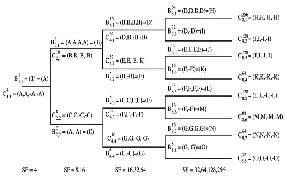
Fig. 3.4.Code tree of both NOVSF and BOVSF
codes.
4. SIMULATION & RESULTS
Event driven simulation has been considered for getting results. The call arrival process is assumed to be poison with mean arrival rate λ varying from 1 to
128 call/unit time. The possible OVSF & NOVSF code rate considered are R,2R,4R and 8R, corresponding to four different classes. Simulation results are presented to show the call blocking probability of OVSF and NOVSF Code.
Pb (%) = No. of Call Blocked
Total no. of Call
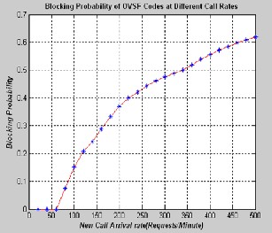
Figure S1: Blocking probability of OVSF codes at different call rate
International Journal of Scientific & Engineering Research, Volume 3, Issue 11, November-2012 5
ISSN 2229-5518
REFERENCES:
1. “Non Blocking OVSF Codes Influence The Performance Of WCDMA System “Shailendra Mishra The 2006 International Conference on Communications in Computing (CIC'6: June 26-29,
2006, Las Vegas, USA)
2.Third Generation Partnership Project Technical Specification Group Radio Access Network Working Group 1, “Spreading and Modulation,”
(1999-9).
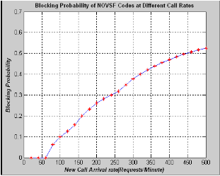
Figure S2: Blocking probability of NOVSF codes at different call rate
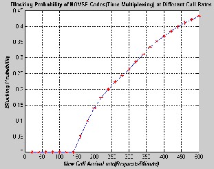
Figure S3: Blocking probability of NOVSF (Time- Multiplexing) codes at different call rate.
5. Conclusion
I have proposed use of non-blocking OVSF (NOVSF) codes in the sense that all codes are orthogonal to each other and no code blocks the assignment of any other NOVSF codes. As the graphs of Blocking probability Vs New call arrival rate (request/minute) show that NOVSF codes produce less code blocking then OVSF codes, hence we can assign NOVSF code easily to the new user during handover process leading to increased system capacity and high code utilization. Therefore, non blocking OVSF codes are better option for channelization codes in W-CDMA system in near future.
3. F. Adachi, M. Sawahashi and K. Okawa, Tree- structured generation of orthogonal spreading codes with different length for forward link of DS-CDMA mobile radio. Electronic Letters 33 1 (1997).
4. A.J. Viterbi. CDMA: Principles of Spread Spectrum Communication, Addison-Wesley, Reading, MA (1995).
5. 3GPP TS 25.213, v3.3.0, spreading and
Modulation (FDD), October 1999.
6. Tero Ojanpera and Ramjee Prasad, “An Overview
of Air Interface Multiple Access for IMT-
2000/UMTS,” IEEE Communication Magazine,
vol.36 pp. 88-95, September 1998
7. “Performance Analysis of Non blocking OVSF Codes in WCDMA” by Hagan Cam and Kiran Vadde.
8. “Non-blocking OVSF Codes and Enhancing Network Capacity for 3G Wireless and Beyond System” by Hasan Cam.
9. WCDMA FOR UMTS by Harri Holma Antti
Tosklaa.
10. “Quality of Service Based Admission Control for
WCDMA Mobile System” Janne Pollonen.
11. B.Xu, T.B. Vu, and H. Mehrpour, “A Space- Time Rake Receiver for Asynchronous DS-CDMA System Based on Smart Antenna,” in Proc. IEEE Vehicular Technology Conference, 1999.
12. J.G.Prooakis, Digital Communication. New
York, NY: McGraw-Hill Inc., third ed., 1995.
13. K. Vadde, H. Çam, Performance evaluation of OVSF and non-blocking OVSF codes in WCDMA, Submitted for publication.
14. TS 3GPP RAN 25.331 v3.7.0. RRC Protocol
Specification, June 2001
International Journal of Scientific & Engineering Research, Volume3, Issue 11, November-2012 6
ISSN 2229-5518