
International Journal of Scientific & Engineering Research, Volume 4, Issue 4, April-2013 1753
ISSN 2229-5518
IMPLEMENTATION OF KGS BASED CONTROL FOR GEAR SHIFT LEVER LINE
MANUFACTURING SYSTEM
Geeta Khare, Dr. R.S. Prasad
Information technologies have been rapidly developed in recent years, and they have provided sufficient technical support for building modern industrial automation systems with more open architecture with respect to the previous ones. It turns out that the computerized real-time monitoring analysis and automated technologies realize the full automation of an industrial measurement system. The combination of emerging information technologies with traditional condition monitoring systems allows for the continuous running status monitoring for essential equipment as well as comprehensive data processing and centralized resource management. Automation plays an increasingly important role in the world economy. It has notable impact in a wide range of industries beyond manufacturing. Control systems are of growing importance as they are involved in many safety critical industrial applications; civil aircraft, ground transportation, nuclear power plant, etc. For automation of production planned either centralized or distribution control systems are used. In this field, a lot of activity has been devoted to ensuring and improving hardware and software reliability.
Various aspects of centralized and distributed digital control and its pros and cons have been studied. Here an attempt is made to overcome the disadvantages of above system to improve efficiency as well as profit level by going into minute details from root to top level i.e. on line operator up to management or supervisor level, the system named as KGS i.e. Kaleidoscopic Governing systems. The ‘KGS’ system is implemented in the operation of manufacturing of GSL Line which is used in automobile sector & shows how it is efficient in improving plant availability.
Keywords: Conduit, Crimping, Distributed Control Systems, Grommet, GSL, KGS.
In the past years before the personal computer (PC) was widely incorporated into industrial automation systems, all the faults that occurred in industrial processes were checked and dealt with by trained or experienced operators. All operations were handled in a manual or semiautomatic manner which, however, had some major drawbacks. For instance, the operator had to do the majority of the work by hand, the abnormal conditions could not be monitored and handled in real time, the remote measurement parameters could not be effectively monitored, and operators were prone to make mistakes in recording and manipulating a large amount of data. So it became necessary to automate the measurement operations as well as to improve the operating efficiency.
Today’s work environment has been revolutionized by PC’s and PC workstation. One of the most dramatic changes has taken place in industrial control centers. Previously the Distributed Control Systems equipments were big, bulky, and noisy had no ergonomic consideration. Hence, support equipments like hardwired alarms, phones, PA systems and PCs were difficult to incorporate in the design. They were just bad add on accessories which impact the operator’s performance and that human error was present in a number of different control systems. Many
IJSER © 2013 http://www.ijser.org
International Journal of Scientific & Engineering Research, Volume 4, Issue 4, April-2013 1754
ISSN 2229-5518
systems are plagued with issues that make it very difficult for an operator to detect, diagnose and respond to an abnormal situation.
In this field, a lot of activity has been devoted to ensuring and improving hardware and software reliability. In the recent years, some hardware /system manufactures also began to develop their industrial automation software products. The representative products primarily include Cimplicity of GE (U.S.A.) RS view of AB (U.S.A) Win CC of Siemens (Germany) and so on. Some DCS manufacturers such as Rosemount and Honeywell also developed powerful industrial automation software for their advanced control system and field-bus products.
Productivity improvement techniques are based on factors such as: technology, employee, material, process, product and management. Productivity refers to efficiency of the Production System. It is an indicator of how well the factors of production i.e. land; capital, labour, energy etc. are utilized. European Productivity Agency (EPA) has defined productivity as “Productivity is an attitude of mind. It is the mentality of progress of the constant improvements of that which exist. It is the certainty of being able to do better today than yesterday and continuously. It is the constant adaptation of economic and social life to changing conditions. It is continual efforts to apply new technique and methods. It is the faith in human progress”.
The main objective of the production is to satisfy the internal customer’s needs by effective planning of resources, processes and interdepartmental coordination to ensure delivery complying with plan quality policy. The production has continued process. Production or manufacturing department involves in various processes starting from collection of material for assembly till dispatch. A press shop which manufactures components for automobiles is expected to deal in large volumes. Most components are small in size and are precision jobs. Hence loading the raw material into the press becomes critical, and the rate of production depends entirely on the loading and unloading speed. An operator designated for this job will frequently experience boredom and exhaustion, each of which affects the productivity of the plant. This menial job is best left to an automated process and the operator can be assigned to more fitful jobs where his skills are best utilized.
There are large variety of product lines for automatic cables, mirrors, washing systems, gear shifters and Parking Brake Lever for four wheelers. Customers demand is increasing but line capacity is less considering shift basis. For customer demand meet required machine productivity should be increased. So, study is concentrated on “Productivity improvement through KGS.
The advancement in embedded technology is used to take care of local parameters. It gives full facility to local operator to interact with the process using keyboard & LCD display. The settable alarm method & alert message reduce operating skills & breakdown time. It has enough memory to take care of data. The data memory will be refreshed every time & data of interest of
IJSER © 2013 http://www.ijser.org
International Journal of Scientific & Engineering Research, Volume 4, Issue 4, April-2013 1755
ISSN 2229-5518
management will be sent to a pc through simple Ethernet data highway. The pc memory if not enough to take care of all data of interest then it can be transferred to special data storage element. The data of interest of respective department is also stored at the PC of that department. We have provided simple embedded controller at each control section which not only takes care of its own section to optimize system but at the same time communicates with supervisory pc and alerts for present status by giving data. This gives benefits in following way.
It ensures simple and fast engineering and no probability of programming errors and ensures fast commissioning as all the cards of compatible.
It ensures a significant boost in productivity throughout the entire life cycle of the plant.
It is designed to provide higher plant availability and productivity.
Reduce plant down times as well as operating and maintenance cost as only card replacement in worst case.
No skilled man power is required so all process control components reduce down time in the case of problem or other events and minimize production losses.
There is no single point of decision making and therefore there is no single point of failure.
Increased reliability with decreased communication costs.
DCS delivers the needed response time, and enhances system survivability increases reliability and lower cost.
A simple PC can acquire data for MIS purposes.
Data transparency up to the managerial level in real time
Resolution can be increased.
Non linearity will take care off.
Gears are the most common means of transmitting power in Mechanical Engineering. Gears form vital elements of mechanisms in many machines such as vehicles, metal tooling machine tools, various engines. A gear box is used for transfer of the power of the engine to the wheels through a differential. Gear shifting products includes Rod type systems, Cable type systems, Dashboard systems, ultra compact systems, with illuminated, colorful covers and knobs. Gear shifting systems increase layout possibilities for the shifter with respect to state of the art parking brake lever and cable assembly lines.
Gears are selected by manipulating a lever called a gear stick, shift stick, gearshift, gear lever, gear selector or shifter connected to the transmission via linkage or cables and mounted on the floor, dashboard or steering column. Moving the level forward, backward, left and right into specific positions selects particular gears. There is no gear shift and clutch pedal in an automatic transmission car. The automatic transmission primary job is to allow the engine to operate in its narrow range of its speed while providing a wide range of output speeds. Transmission uses gears to make more effective use of the engine torque, and to keep the engine operative at an
IJSER © 2013 http://www.ijser.org
International Journal of Scientific & Engineering Research, Volume 4, Issue 4, April-2013 1756
ISSN 2229-5518
appropriate speed. When towing or hauling heavy objects vehicles transmission get hot enough to burn of the transmission fluid. To protect the transmission from serious damage vehicles equipped with transmission coolers.
Nano has a cable type gear shifter, as opposed to rod type which is first for a small car in India. This helps in two ways – firstly it reduces the weight of the overall gear shifter system and secondly it makes shifting of gears much smoother.
Manual transmission also known as manual gear box or standard transmission is a type of transmission used in motor vehicle applications. Manual transmission often feature a driver operated clutch typically operated by a foot pedal and a movable gear stick either operated by foot or by hand as an automobile.
The manual transmission provides a means of varying the relationship between the speed of the engine and the speed of the wheels. Varying these gear ratios allows the right amount of engine power at many different speeds. Manual transmissions require use of a clutch to apply and remove engine torque to the transmission input shaft. The clutch allows this to happen gradually that so that the car can be started from a complete stop. Modern manual transmissions do not disengage any of the forward drive gears; they are simply connected to their shafts through the use of "synchronizers". Reverse is achieved through reverse idler gears, which are engaged to move the car backwards. The key difference between a manual and an automatic transmission is that the manual transmission locks and unlocks different sets of gears to the output shaft to achieve the various gear ratios, while in an automatic transmission the same set of gears produces all of the different gear ratios. The planetary gearset is the device that makes this possible in an automatic transmission.
Vibrations are isolated because cables are not as rigid as rods, have less weight and the frequency of vibration shifts from the gearbox to the cables. There is also an isolation of noise through a damper system that breaks the transmission of noise and smoothens gear shifting. These systems also improve safety performance and reduce fitting and assembly time. To optimize production and quality processes, stringent quality checks are made at each stage of the production process.
Operation on gear shift lever line is shown in fig. 1. There are five stations where various operations on cable are performed to produce final products. Each station checks certain parameter for quality norms by using logical circuit or scheme call Pokoyoke which is standard method in automobile production line. Air pressures, mechanical damage hydraulic pressure if applicable are common points for all stations which operator usually check. Each station is provided with individual KGS controller which takes care of the station operations as well as communicates status to next station and also sends information to computer for MIS purpose. The controller has two cards; Microcontroller and Input – Output with power supply
IJSER © 2013 http://www.ijser.org
International Journal of Scientific & Engineering Research, Volume 4, Issue 4, April-2013
ISSN 2229-5518
1757
respectively. Microcontroller card has hardware with suitable software for respective unit. It also has communication post for PC interface to provide data to PC. All units have same microcontroller and input-output cards so they are compatible to each other. The only change in software program required for each stage. Normally final station is only connected to computer to get idea about the production status for MIS.
l-EER © 2013
International Journal of Scientific & Engineering Research, Volume 4, Issue 4, April-2013 1758
ISSN 2229-5518
STATION-1—PROTECTOR INSERTION, PEELING, CRIMPING, METAL BUSH
INSERTION.
KGS- CONTROLLER-1
STATION-2—GROMET INSERTION &
FITTING
KGS-
CONTROLLER-2
STATION-3—GREASING OF CABLE END FITTING, CEF CRIMPING
KGS- CONTROLLER-
3
COMPUTER ONLY FOR MIS & NOT FOR
CONTROL
STATION-4—TRACTION & LENGTH CHECKING
KGS- CONTROLLER-
4
STATION-5—CHECKING OF CABLE VISUALLY, LENGTH, STROKE LENGTH,
FORCE TEST
KGS- CONTROLLER-5
VARIOUS OPERATIONS ON GEAR SHIFT LEVER PRODUCTION LINE
FIG.1
IJSER © 2013 http://www.ijser.org
International Journal of Scientific & Engineering Research, Volume 4, Issue 4, April-2013 1759
ISSN 2229-5518
Station 1: At this station the following operation takes place
Mechanical protector insertion
Peeling off black coating of cable
Checking of metal bush insertion
Crimping of cable
Crimping is most extensively used in metal working. Crimping is a cold working technique and can be used to form a strong bond between the work piece and in non-metallic component, the efficient interconnection of two adjacent members of linkage system. Sound and vibration isolation means is provided, which is being disposed between the transmission and shifter.
Station 2: operation takes place in this section are:
Grommet is inserted and fitted
Conduit peeling on another side
Metal bush checking
Crimping on another side
A Grommet, used for cable protection, is a ring inserted into a whole through thin material. It is generally flared or collared on each side to keep them in place, and are often made of metal, plastic or rubber. They may be used to prevent tearing or abrasion of the pierced material, to cover sharp edges of the piercing, or both.
It protects the wiring / cabling from contamination from dirt, air, water etc. The smooth and sometimes soft inner surface of the grommet shields the wire from damage. The grommets and the mounting posts are received in an aperture mounted plate rigidly secured to the transmission insuring smooth operation and a good feel.
Station 3: following functions are performed in this section:
Greasing of cable
End fitting & spring presence checking
Crimping CEF
The point of contact of the gear teeth is well lubricated with gear oil. Gear oil has a characteristic aroma due to the addition of sulfur-bearing anti-wear compounds. These compounds are used to reduce the high sliding friction by the helical gear cut of the teeth.
Cleanliness is critical when repairing and servicing standard transmission. The gear oil must be very clean and free of abrasive materials to avoid wearing of the gears. Greasing quantity is checking 10 nos. cable weights before and after greasing.
Manual transmissions are lubricated with gear oil or engine oil in some cars, which must be changed periodically in some cars, although not as frequently as the automatic transmission fluid in a vehicle so equipped.
IJSER © 2013 http://www.ijser.org
International Journal of Scientific & Engineering Research, Volume 4, Issue 4, April-2013 1760
ISSN 2229-5518
Station 4:
The strength of cable is checked by applying force called traction i.e. the load bearing capacity of the cable.
The length of cable verification within tolerance
Station 5: Finally at this stage:
Visual check points like burr, etc.,
Length checking and all accessories check like grommet, end fitting etc.
The experimental results shows the system functionality & performance operations on Gear Shift Lever Line everyday for two months. To achieve breakeven point production should be minimum 1050 units per day & maximum capacity with all parameter normal for centralized system is 1350.
TABLE 1
Day | Production / Day centralized system | Breakeven value | Predicted With KGS | |
Month 1 | Month 2 | Breakeven value | Predicted With KGS | |
1 | 1210 | 1360 | 1050 | 1360 |
2 | 1210 | 1360 | 1050 | 1360 |
3 | 1212 | 1245 | 1050 | 1360 |
4 | 1212 | 1105 | 1050 | 1360 |
5 | 1215 | 1100 | 1050 | 1360 |
6 | 1070 | 987 | 1050 | 1300 |
7 | 1070 | 940 | 1050 | 1300 |
8 | 1070 | 900 | 1050 | 1300 |
9 | 1125 | 1360 | 1050 | 1300 |
10 | 1212 | 1360 | 1050 | 1360 |
11 | 1210 | 1360 | 1050 | 1360 |
12 | 1200 | 310 | 1050 | 1360 |
13 | 1080 | 300 | 1050 | 1300 |
14 | 1080 | 1220 | 1050 | 1300 |
15 | 1080 | 1360 | 1050 | 1300 |
16 | 1200 | 1360 | 1050 | 1360 |
17 | 1210 | 1270 | 1050 | 1360 |
18 | 1220 | 1300 | 1050 | 1360 |
19 | 1180 | 226 | 1050 | 1300 |
IJSER © 2013 http://www.ijser.org
International Journal of Scientific & Engineering Research, Volume 4, Issue 4, April-2013 1761
ISSN 2229-5518
20 | 1180 | 321 | 1050 | 1300 |
21 | 1140 | 700 | 1050 | 1300 |
22 | 1200 | 1360 | 1050 | 1360 |
23 | 1215 | 1390 | 1050 | 1360 |
24 | 1210 | 1220 | 1050 | 1360 |
25 | 1140 | 1360 | 1050 | 1300 |
26 | 1170 | 1360 | 1050 | 1300 |
27 | 1170 | 1360 | 1050 | 1300 |
28 | 1180 | 1360 | 1050 | 1300 |
29 | 1227 | 1360 | 1050 | 1360 |
30 | 1230 | 1360 | 1050 | 1360 |
The production per day under centralized and predicted with KGS system for two months is shown in table1. It is observed from fig.2 that in centralized system production is varying above and below breakeven points i.e. profit margin lowers. Profit margin increases under
KGS as full capacity of plan utilization (1350 units) are observed i.e. above breakeven points.
1600
1400
1200
1000
800
600
400
200
0

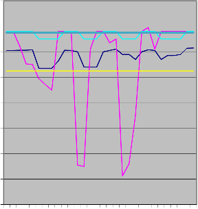
1 4 7 10 13 16 19 22 25 28
CENTRALISED SYSTEM MONTH 1
CENTRALISED SYSTEM MONTH 2
BREAKEVEN PREDICTED WITH KGS
WITH ALL PARAMETER NORMAL FOR CENTRALISED

Fig.2
IJSER © 2013 http://www.ijser.org
International Journal of Scientific & Engineering Research, Volume 4, Issue 4, April-2013 1762
ISSN 2229-5518
TABLE - 2
Months | Centralized | KGS System | ||
Productivity % | Productivity / cost ratio | Productivity % | Productivity / cost ratio | |
1 | 90 | 4.5 | 90 | 4.5 |
2 | 70 | 3.5 | 100 | 5 |
3 | 100 | 5 | 95 | 4.75 |
4 | 70 | 3.5 | 90 | 4.5 |
5 | 20 | 1 | 100 | 5 |
6 | 70 | 3.5 | 100 | 5 |
7 | 55 | 2.75 | 90 | 4.5 |
8 | 70 | 3.5 | 100 | 5 |
9 | 100 | 5 | 80 | 4 |
10 | 35 | 1.75 | 100 | 5 |
11 | 60 | 3 | 100 | 5 |
12 | 60 | 3 | 95 | 4.75 |
100%
90%
80%
70%
60%
50%
40%
30%
20%
10%
0%
1 2 3 4 5 6 7 8 9 10 11 12
KGS System Productivity /
cost ratio
KGS System Productivity
%
Centralized Productivity /
cost ratio
Centralized Productivity % Months
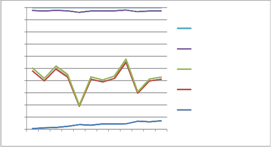
Fig. 3
IJSER © 2013 http://www.ijser.org
International Journal of Scientific & Engineering Research, Volume 4, Issue 4, April-2013 1763
ISSN 2229-5518
Table 2 shows the production percentage and production per cost ratio for 12 months in present centralize system and with KGS Gear Shift Lever Line system. Plant efficiency increased as shown in fig. 3. We find better output with respect to cost incurred in KGS Gear Shift Lever Line system. The KGS system shows positive impact on efficiency and reliability of the plant.
The system is designed for the future to guarantee compatibility with ongoing innovations. It provided practical work environment that looks good, reduces stress and fatigue, and helps the operators perform their tasks efficiently.
KGS Systems offers a highly innovative distributed control system that helps the industry not only stay competitive but improve competitiveness over the long term – by optimizing productivity, plant availability, reduce down times and cost. It significantly enhances the working efficiency of system operators and decision makers. By this it can be achieved full industrial automation which has a positive practical significance in both economy and technology perspectives.
References:
[1] Bela G Liptak, “Process Control,” 3rd Edition, Butterworth Heinemaun
[2] Sanjeev gupta &S.C.Sharma Selection and application of advance control systems
Journal of scientific & Industrial Research – April 2005
[3] Bela G Liptak. “Process Measurement And Analysis” Third Edition, Butterworth,
Heinemaun
[4] The Operator as IPL – Author,
[5] User Centered Design Services, LLC, USA, Hydrocarbon Engineering, Sept. 2005
[6] Control System Design – Graham C, Goodwin, Steford F Graebe, Mario E Salgado.
Prentice Hall.csd. Newcastle.edu.au
[7] The Engineering tool Box.com
[8] Resources, Tools and Basic information for Engineering and Design of Technical
Applications.
[10] en.wikipedia.org/wiki/Parking .brake
[11] modern industrial automation software design, by L.Wang & Dr. K.C.
Tan, The Institute of Electrical & electronics engineers, Inc., [16] Manual transmission – Wikipedia
[17] Formal Design of Distributed Control Systems With Lustre, Paul Caspi, Christine
Mazuet, Rym Salem & Daniel Wever.
[18] Auto car professional – Essentials reading for the automotive industry- www.autocarpro.in
[19] Gearbox overview Johnson Electric – www.saia-motor.com
IJSER © 2013 http://www.ijser.org
International Journal of Scientific & Engineering Research, Volume 4, Issue 4, April-2013
ISSN 2229-5518
1764
l-EER © 2013