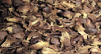
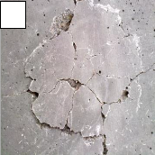
 Fig (1): Oil palm shells
International Journal of Scientific & Engineering Research, Volume 3, Issue 11, November-2012 1
ISSN 2229-5518
a- College of Engineering, UNITEN, Malaysia
*Prof Zakaria Vhe Muda, Head of Civil Engineering Dept., E-mail: MZakaria@uniten.edu.my,
**Ass Prof Salah F.A. Sharif, Research Fellow, E-mail: salah@ uniten.edu.my
*** Eng. Tan Yen Lun, E-mail: tanyen@uniten.edu.my
Green technology and sustainable development are the main concern in any country around the world; researchers and engineers are urged to provide the best solution to maintain the environment for the future generation. Malaysia is the world largest oil palm exporter, producing over 4 million tons of oil palm shells as main solid waste of the industry annually, which causing an environmental problem. An optimum mix design should be acquired through various trial mixes to ensure the re-use of oil palm shells lightweight concrete to achieve the required structural performance. A self-fabricated drop-weight impact test rig, have been used in this research work, to simulate a low-velocity projectile impact on the slab specimens. Three parameters are tested for specimens with or without geogrid reinforcement; where the first parameter is the effect of OPS content on impact resistance, and it is found out that the increment of OPS content will reduce the impact resistance of concrete. For the second parameter, the effect of geogrid layers on impact resistance is evaluated; as the increment of geogrid layer does improve the impact resistance, but the effect is more obvious for ultimate crack resistance than the first crack resistance. The last parameter is the contribution of geogrid type on impact resistance; comparison are made between geogrid 60/60 and geogrid 80/80, result show that geogrid 80/80 has the overall better performance.
Development of lightweight concrete (LWC) has been one the most interesting subjects in sustainable construction materials and concrete industry; as lightweight concrete gives economical and structural benefits. Lightweight concrete decreases the total dead load of a structure, which allows the structural engineers to reduce the size of structural members such as columns, foundation and other load bearing structures while contribute and maintain the structural performance. From the economical aspect, the reduction of structural members’ size is as equal as the reduction of construction costs. The amount of materials used such as coarse aggregate, fine aggregate, cement, steel bars and formworks will also decrease. In the concrete industry, lightweight concrete is developed through replacement of conventional aggregates with a material that has less weight.
Generally, lightweight concrete is produced with various type of lightweight aggregate (LWA)
such as expanded shale, clay or slate materials that have been fired in a rotary kiln to develop a
IJSER © 2012 http://www.ijser.org
International Journal of Scientific & Engineering Research, Volume 3, Issue 11, November-2012 2
ISSN 2229-5518
porous structure. Many other natural, such as pumice, or artificial or recovered wastes alternatives where used as light weight aggregates.
In Malaysia, various researchers and engineers have been looking for a suitable material for lightweight concrete technology With the sustainability and environmental issue the oil palm shells (OPS), an agricultural solid waste, is one of the alternative materials found to be replacing the conventional aggregate in production of lightweight concrete.
In conjunction of growing global demand for edible oils in the last two decade, Malaysia becomes the largest oil palm exporter in the world and oil palm has been one of the major incomes for the country. However, the oil palm industry also contributes many impacts to the countries environment; one of those impacts, producing over 4 million tons of oil palm shell annually. Without a proper utilization method for such vast number of oil palm shells, the oil palm shells become untreated waste and causing pollution to the environment; as the current oil palm shells disposal method is through incineration which contributes to air pollution. Hence,
lead to the research and development on the utilization of oil palm shell in various ways, from furnace fuel to concrete industry. The utilization of Oil Palm Shells (OPS), in concrete industry is very rewarding for both agricultural sector and concrete industry. As for the agricultural sector, oil palm shells wastes may be sold as useful materials and reduce wastage; while for the concrete industry, the discovery of substitute, less cost, material for conventional aggregate in lightweight concrete development and may preserve the natural resources and saving energy due to acoustic and thermal insulation facility of the lightweight cast/precast concrete products. Sustainability indicators then were obviously fulfilled in reusing wasted shells.
Past researches have indicated that oil palm shell lightweight concrete is found to be yielding high compressive strength, up to 30MPa. The high strength oil palm shells lightweight concrete can be an ideal replacement for conventional concrete in structural system. In this research work, investigations of precast slabs using lightweight concrete with OPS were performed with and without Geogrid reinforcement. The study will include the following:
i- To determine the relationship of OPS lightweight concrete impact resistance and
OPS content without Geogrid reinforcement.
ii- To determine impact resistance of OPS lightweight concrete slab with and without
Geogrid, which includes:
a- Relationship between crack resistance and Geogrid layers b- Relationship between crack resistance and Geogrid types
Structural lightweight concrete is defined as concrete which is made from lightweight aggregates conforming to ASTM C 330, has a compressive strength in excess of 17.25MPa at 28 days of age when tested in accordance with methods stated in ASTM C 330 and has an air-dry density not exceeding 1,840 kg/m3 as determined ASTM C 567 [1]. For job specifications, lightweight concrete is allowed to have up to density not more than 2000kg/m3. Generally, lightweight concrete able to achieve compressive strength same as the normal concrete while having lower weight; up to 25% and 35% lighter.
In general, lightweight aggregate is classified into three categories; which are natural lightweight aggregate, manufactured lightweight aggregate and lightweight aggregate from industry by- product or agricultural waste. For the natural lightweight aggregate, it is very rare to acquire and can only be found in some parts of the world; diatomite, pumice, scoria, volcanic cinders and tuff
IJSER © 2012 http://www.ijser.org
International Journal of Scientific & Engineering Research, Volume 3, Issue 11, November-2012 3
ISSN 2229-5518
are the natural lightweight aggregate available but not extensively used in the construction industry due to their rarity. The second category, manufactured lightweight aggregate is categorized as raw materials that undergo certain manufacturing methods which cause expansion and therefore reduce the apparent specific gravity. In the industry, the manufactured lightweight aggregates commonly used are expanded clay, shale and slate. The manufacturing method of those lightweight aggregates is heating the chosen raw materials in a rotary kiln which will cause the materials to expand or “bloat”, resulting in a porous product. When cooled, the materials will retain their physical strength but with lower weight (lower density). The last type of lightweight aggregate can be acquired from industry byproduct or agricultural sector. In heavy industry- based country, by-products such as fly ash, recycled papers or unusable tire (rubber) are the available materials can be utilized in the lightweight concrete development. While for country with agro-based, agricultural waste is the material that can be utilized. If the waste is not utilized properly, it may contribute to environmental problems.
In conjunction of both sustainable development and lightweight concrete technology has lead to utilization of oil palm shells in the field, due to its physical properties. Briefly, oil palm shell is the hard endocarp that surrounds the palm kernel. It is separated from the kernel during the palm oil extraction process whereby the shell is the by-product of the process. Oil palm shells are naturally sized, hard and lighter than the conventional aggregates. Due to the stiff surfaces of oil palm shells organic origin, they will not contaminate or leach to produce toxic substances once they bound in the concrete matrix [2]. The lightness in weight of oil palm shells also further enhance its suitability as substitute aggregates in lightweight concrete development.
Nevertheless, using oil palm shells as aggregate in concrete industry is no longer a new discovery. A lot of researches have been carried out using oil palm shells in lightweight concrete technology, however most of the concrete are low strength and only adopted to use in non- structural concreting or low strength requirement structure such as pavement and wall. In 2006, D.C.L. Teo, M.A. Mannan, V.J. Kurian and C. Ganapathy stated that oil palm shells concrete can also be used for the construction of low-cost houses. For the period from 2001 to 2005, the demand of low-cost houses in Malaysia was 232,000 units. To address this need, Universiti Malaysia Sabah (UMS) is actively involved in research to achieve affordable and comfortable houses. A model low-cost house of 58.68m2 area which was built in 2003 using „Oil Palm Shell hollow blocks‟ for walls and „Oil Palm Shell concrete‟ for footings, lintels and beams is performing well and has no structural problems at all [3].
In 1998, H.B. Basri, M.A. Mannan and M.F.M. Zain investigated the workability, density and compressive strength development of oil palm shell lightweight concrete over 56 days under three curing conditions. It is found that the fresh oil palm shell concrete have better workability while its 28 days air-dry density was 19%-20% lower than conventional concrete and the 56 days compressive strength is 41%-50% lower than conventional concrete. Nonetheless, the results were still within the range of structural lightweight concrete [4]. In 2003, M.A. Mannan and C. Ganapathy researched on oil palm shell lightweight concrete where the results show the concrete able to achieve lightweight category with bulk density of 1850kg/m3. The oil palm shell concrete mix also able to reach 28 days compressive strength from 20 to 24 N/mm2; which also satisfy the structural lightweight concrete strength requirement [5].
IJSER © 2012 http://www.ijser.org
International Journal of Scientific & Engineering Research, Volume 3, Issue 11, November-2012 4
ISSN 2229-5518
The utilization of oil palm shells in lightweight concrete field is being a potential research; as it benefits the environment, the construction, the concrete technology as well as the future generation. The utilization may reduce the wastage of oil palm shells and turn it into useful aggregate in concrete industry. In addition, oil palm shells are abundant and available from any oil palm mill in the country.
Fig (1): Oil palm shells
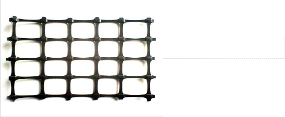
Geogrid is a mesh materials made of high-modulus polymer material such as polypropylene and
polyethylene. In geotechnical field, geogrid is used as reinforcement in some geo structures. Geogrids are made of relatively netlike materials with openings called apertures which are large enough to allow for soil strike-through from one side of the geogrid to the other, as well as allowing interlocking with the surrounding soil or rock to perform the function as reinforcement or segregation, or both (Fig. 2). Geogrids are manufactured in a way that the grids are greater than 50 percent of the total area. They develop reinforcing strength at low strain levels, such as 2 percent [7]. In geogrids manufacture, the generally used polymeric materials, high density polyethylene (HDPE), polypropylene (PP), and polyester (PET) offer excellent chemical resistance. With this features, geogrid is a potential alternative of steel reinforcement in concrete, especially in thin sections and in architectural components [6]. Corrosion resistance of geogrids also is a great advantage in construction materials.
However, there is not much research has been done using geogrid as reinforcement in oil palm shell lightweight concrete. Few papers were published on geogrid as reinforcement in Portland concrete; one of them is from Tang, Chehab and Kim. They carried out a laboratory study of geogrid as reinforcement in Portland cement concrete to assess the feasibility of using geogrid as potential reinforcement in thin concrete pavements and overlays to enhance the tensile strength and ductility.
Concrete beams with dimensions of 15cm x 15cm x 56cm were casted with reinforced geogrids in different amount of layers were tested in three point loading to compare analysis with the control concrete beam (no reinforcement). The results of the study show that geogrid reinforcement did provide substantial post-cracking ductility. Failure modes for both reinforced and un-reinforced concrete are different. For the concrete reinforced with geogrid, it was observed that the geogrid mobilized at the time of crack initiation and extensive crack propagation with wide crack mouth opening was found before failure. While for the control beam (un-reinforced), it fails in brittle mode instantaneously.
The potential of geogrid to replace conventional can be investigate in line of oil palm shell lightweight concrete development. Geogrid can be the ideal replacement for conventional steel
IJSER © 2012 http://www.ijser.org
International Journal of Scientific & Engineering Research, Volume 3, Issue 11, November-2012 5
ISSN 2229-5518
bars as reinforcement to produce high strength lightweight concrete. Its physical properties like low density, low weight, flexibility and durability may make it a more reliable reinforcement.
Concrete is one of the basic materials for constructions nowadays, it is used in almost every
structural members such as beam, wall, slab and column. Concrete solidifies and hardens after mixing and will bond together and able to form a high-strength (compressive strength) composite. However, there is no formula or theory to indicate high compressive strength concrete able to resist high-strain loading (dynamic loading). In design process, impact toughness of concrete is often neglected or least considered; in fact, high loading rate are frequently encountered in engineering problems.
During the service life of a structure, impact loading will occur in many forms such as fall of objects, flying objects and traffic accidents or explosion accidents. The understanding of concrete under dynamic loading is important in designing certain type of buildings such as nuclear power plant, roadside curb, and protective wall on mountain side to prevent rock fall and bridges to resist impact of ships. If concrete is exposed to a large high-strain rate loading, there is a possibility of punching shear failure to happen. And hence reduce the capability of structures to resist larger load and transfer load to other structural members. Impact loading can lead to different types of global or localized damage, including flexure penetration and scrabbling, spilling, perforation and punching shear failure [8].
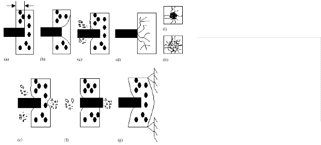
In 2005, according to a paper regarding local impact effects of projectile on concrete published by Q.M. Li, S.R. Reid, H.M. Wen and A.R. Telford, there are seven types of phenomena associated with projectile impact effects: a) Penetration – Tunneling into target by the projectile (the length of the tunnel is called the penetration depth); b) Cone cracking and plugging – Formation of a cone-like crack under the projectile and the possible subsequent punching-shear plug; c) Spilling – Ejection of target material from the proximal face of the target; d) Radial cracking – Global cracks radiating from the impact point and appearing on either the proximal or distal face of the concrete slab or both, when cracks develop through the target thickness; e) Scabbing – Ejection of fragments from the distal face of the target; f) Perforation – Complete passage of the projectile through the target with or without a residual velocity; g) Overall structural responses and failures – Global bending, shear and membrane responses as well as their induced failures throughout the target [9].
IJSER © 2012 http://www.ijser.org
International Journal of Scientific & Engineering Research, Volume 3, Issue 11, November-2012 6
ISSN 2229-5518
In a concrete behavior impact modeling by J.F. Georgin and J.M. Reynouard, propagation velocity of the stress waves depends on the local material stiffness which is given by the material constitutive law. It stated that concrete shows and increase in stiffness as the strain rate increases, a phenomenon called strain rate effect [10].
However, impact resistance or impact strength is a parameter that difficult to determine as there are various method of testing; from ACI impact test, drop-weight impact test to computational approach such as finite element analysis. All of the testing methods are very distinguish and have their own limitations and theories. In a simple word, unlike compressive strength of concrete, there is no standard testing methods for impact strength or measure the toughness of concrete. Due to the lack of standard parameters and standard testing method, impact resistance cannot be fully quantified in a concrete designing process.
Impact resistance or impact strength or toughness of concrete is one of the aspects needed to be concerned in designing concrete durability. In the practical field, the designing stage of a concrete structure often neglects the importance of impact strength or concrete toughness. In most of the concrete structure design, only compressive strength is taken into account as the primary requirement. In the ultimate limit state design, it is common to design using the compressive strength as main parameter. Although compressive strength contribute to the load- bearing capacity of the structure, the parameter has yet able to accommodate for the durability requirement. In the serviceability state design, which concern of the durability of a structure throughout its service life; parameter such as fire resistance, blast resistance and impact resistance are very important.
As mentioned, there is no standardized testing method to measure the impact resistance of a
concrete or to justify the parameters affecting the impact resistance of a concrete. Researchers, engineers and also military had developed various impact resistance testing methods; from
IJSER © 2012 http://www.ijser.org
International Journal of Scientific & Engineering Research, Volume 3, Issue 11, November-2012 7
ISSN 2229-5518
computational simulation and modeling to actual experimental tests such as small-scale lab tests or full-scale prototypes tests, high velocity projectile impact test using missile or ballistic to low- velocity projectile impact test by dropping heavy mass. In addition, the ACI committee also conducted an impact test using small drop-weight mechanic. All the impact testing methods have different parameters, specimen samples, testing apparatus, impact loading rates, projectile patterns and results.
ACI Drop-Weight Impact Test
The ACI drop-weight impact test is fabricated and designed by the ACI committee 544 to
measure the impact resistance of fiber-reinforced concrete. The modified ACI impact test recommended that a hammer weighing 44.7N is dropped from a height of 457mm on a 63.5mm diameter hardened steel ball that is placed on the top of the center of a 150mm x 63.5mm cylindrical concrete specimen. The specimen’s initial failure and ultimate failure are recorded the number of blows required to failure initiation. Initial failure id identified by the appearance of first visible crack; while the ultimate failure is when the crack spread until the specimen touches the steel lugs [11]. Looking at the specimen aspect such as size and shape, the ACI impact test used a special-made specimen shape; where the a 150mm diameter concrete with 50mm thickness is modified with two 25mm triangular notches. The notches are used to force the crack propagation in a predefined path. Any failure that does not occur in the predefined path is rejected.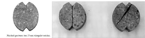
The impact resistance is recorded in a way that the numbers of blows required to initiate (serviceability limit) and propagate cracks until ultimate failure (ultimate limit). The ACI impact test is based on statistical analysis where the data is presented in a distribution graph, where the mean, standard deviation and coefficient of variation are determined.
Low-velocity Drop-Weight Impact Test
In contrast of variation of impact testing procedure, the other testing procedure is the low-
velocity drop-weight impact test. In 2005, G. Ramakrishna and T. Sundararajan conducted a comparative study on natural fiber reinforced cement mortar slab using different testing equipment and specimens. Four different natural fibers, coir, sisal, jute and hibiscus with four different fiber contents (0.5%, 1.0%, 1.5% and 2.5% - by weight of cement) and three fiber lengths (20mm, 30mm and 40mm) are considered and analyzed. The study used a self fabricated drop-weight impact test; by dropping steel ball weighing 0.475kg with drop height of 200mm on
IJSER © 2012 http://www.ijser.org
International Journal of Scientific & Engineering Research, Volume 3, Issue 11, November-2012 8
ISSN 2229-5518
the specimen. The specimen used is a square shape slab with dimension of 300mm x 300mm x
20mm and freely supported on a self-fabricated mild steel frame [12].

According to the comparative study, when the drop-weight projectile is dropped on the specimen, the potential energy loss is absorbed and dissipated as strain energy and thus causing cracks due to stresses. The width of crack developed is related to the intensity of the energy, the amount of energy absorbed and the concrete properties. In addition, the crack pattern developed is also dependent on the concrete properties. The relationship of potential energy of a drop- weight projectile and the strain energy dissipated in cracks development is expressed as following:
Ne = Ru* lc* dc* wc ……………………………………………………………………. (eq.1) Where, N = No. of Blows
e = Energy per blow (Joules)
lc = Total length of all cracks dc = Maximum crack depth wc = Maximum crack width
Ru = Ultimate crack resistance
Another dimensionless factor „impact crack resistance ratio‟ was also defined:
Cr = Ru* fcu ………………………………………………………………………………….(eq.2) Where, Cr = Impact crack resistance ratio
fcu = Cube compressive strength
The journal used the above equations to calculate and study the impact resistance for fiber reinforced concrete slabs; it is assumed that the total computed energy imparted is fully absorbed by the specimens.
IJSER © 2012 http://www.ijser.org
International Journal of Scientific & Engineering Research, Volume 3, Issue 11, November-2012 9
ISSN 2229-5518
In an impact resistance study, local damage and overall dynamic response in the form of flexural
deformation will be monitored and evaluated. Local damage includes spilling of concrete at the impact face and scabbing of concrete at the rear face together with projectile penetration into the target. Overall dynamic response consists of flexural deformation resulting flexural or shear failure. The impact energy absorbed by the concrete will be determined. In this project, steel balls with 0.65kg will be dropped at the height of 1000mm on a slab sized 300mm x 300mm x
20mm. The variable parameters will be the percentage of reinforcement in concrete which is geogrid and the compressive strength of oil palm shells lightweight concrete. Both of the parameters will be tested to evaluate their contribution towards the impact resistance of oil palm shells lightweight concrete.
Materials, including, Oil Palm Shells (OPS), Geogrids, River Sand, Ordinary Portland Cement (OPC), Silica Fume, Super Plasticizer and Water, were prepared according to the normal requirements of concrete preparation. Preparation of sample specimens included: i) Setting up the Formworks, ii) Measurement of Workability (Slump Test), iii) Measurement of Workability (Compaction Factor Test), iv) Casting Oil Palm Shells Concrete Slab, v) Curing of Test Specimen. Mix designs were prepared as shown in Table 1.
Testing of Hardened Concrete
1- Slab Specimen Specification
o All the slab specimens will have dimension with 300mm (Width) x 300mm
(Breadth) x 20mm (Height).
o Up to three oil palm shells percentage of slabs will be tested to evaluate the oil palm shells contribution toward crack control; 0.45 OPS/C ratios, 0.50 OPS/C ratios and 0.60 OPS/C ratios will be tested.
o Aside from the oil palm shells percentage, effect from different layers of geogrid on crack control will also be tested. Control specimens, which is without geogrid reinforced will be tested, and then followed by one layer geogrid reinforcement and two layers geogrid reinforcement.
o Table (1) below shows the combination of specimen.
o All the combinations have 3 samples respectively and are tested using the same
testing procedure.
Samples Numbers | OPS Percentage | Type of Geogrid | Geogrid Layers |
0.45/control | 0.45 | 0 | |
0.45/60-1 | 0.45 | 60/60 | 1 |
0.45/60-2 | 0.45 | 60/60 | 2 |
0.45/80-1 | 0.45 | 80/80 | 1 |
0.45/80-2 | 0.45 | 80/80 | 2 |
0.50/control | 0.50 | 0 | |
0.50/60-1 | 0.50 | 60/60 | 1 |
0.50/60-2 | 0.50 | 60/60 | 2 |
0.50/80-1 | 0.50 | 80/80 | 1 |
IJSER © 2012 http://www.ijser.org
International Journal of Scientific & Engineering Research, Volume 3, Issue 11, November-2012 10
ISSN 2229-5518
0.50/80-2 | 0.50 | 80/80 | 2 |
0.60/control | 0.60 | 0 | |
0.60/60-1 | 0.60 | 60/60 | 1 |
0.60/60-2 | 0.60 | 60/60 | 2 |
0.60/80-1 | 0.60 | 80/80 | 1 |
0.60/80-2 | 0.60 | 80/80 | 2 |
2. Impact Test using Fabricated Test Rig
o The fabricated impact test rig will consist of two components; the steel rack with steel channel to allow the drop weight roll from it and the slab holder table for test specimen.
o The test specimen will be put into the slot on the support. The test specimen is
properly fitted so that it won’t bounce away when subjected to impact loading.
o Together with the support, the test specimen is put beside the steel rack.
o The impact load will be subjected at the central of the slab. The steel ball (drop
weight projectile) will be slide from the steel channel at the height of 1000mm.
o Once both slab specimen and drop weight are in position, the steel ball will be released and allow to free fall on the slab specimen.
o Observation is made to spot the initiation of first crack and the ultimate crack.
o Please refer to Appendix F for the set up of drop-weight impact test.
3. Impact Testing Data Acquisition
o Before the specimens are subjected to the impact test, a layer of whitewash is applied at the bottom of the specimen surface to ease the crack observation process during the impact testing.
o In the observation process, two stage of crack initiation is recorded and noted.
The number of blows required to initiate the first crack is recorded as well as the
number of blows required to reach the ultimate failure (when crack propagated through the whole depth of specimen thickness) is also recorded.
o Upon the ultimate failure, the total crack length, the crack width and the crack depth are recorded also for further analysis.
The analysis is done dependent of the data acquired from the hardened concrete testing, which is
impact test. The data is tabulated in Microsoft Excel spreadsheet and analyzed. By using eq. (1) and (2) shown above, the crack resistance, the energy absorbed and the crack resistance ratio of each specimen was calculated. All the data is presented in different type of tables and graphs.
This section presents the raw data acquired from the experimental testing. The analysis of data
and determination of crack resistance for all the specimens’ range, as discussed above will be shown. All the experimental data is acquired from the drop-weight impact test using steel ball with 0.65kg with drop height of 1000mm.
IJSER © 2012 http://www.ijser.org
International Journal of Scientific & Engineering Research, Volume 3, Issue 11, November-2012 11
ISSN 2229-5518
9.1- Raw Data from Impact Test:
Sample Numbers | Maximum Crack Width (mm) | Maximum Crack Length (mm) | Number of Blows (First Crack) | Number of Blows (Failure) |
0.45/control/1 0.45/control/2 0.45/control/3 | 0.330 0.330 0.300 | 339.000 346.000 337.000 | 3 4 3 | 5 5 5 |
0.45/60-1/1 0.45/60-1/2 0.45/60-1/3 | 0.250 0.250 0.200 | 741.000 691.000 722.000 | 7 7 8 | 17 16 15 |
0.45/60-2/1 0.45/60-2/2 0.45/60-2/3 | 0.200 0.250 0.250 | 708.000 745.000 699.000 | 8 7 8 | 21 20 23 |
0.45/80-1/1 0.45/80-1/2 0.45/80-1/3 | 0.200 0.250 0.250 | 741.000 721.000 706.000 | 7 8 7 | 22 20 21 |
0.45/80-2/1 0.45/80-2/2 0.45/80-2/3 | 0.150 0.200 0.200 | 731.000 695.000 714.000 | 7 8 8 | 24 25 25 |
Sample Numbers | Maximum Crack Width (mm) | Maximum Crack Length (mm) | Number of Blows (First Crack) | Number of Blows (Failure) |
0.50/control/1 0.50/control/2 0.50/control/3 | 0.330 0.300 0.330 | 337.000 331.000 335.000 | 3 3 2 | 5 4 4 |
0.50/60-1/1 0.50/60-1/2 0.50/60-1/3 | 0.250 0.250 0.200 | 767.000 694.000 731.000 | 7 6 7 | 15 16 16 |
0.50/60-2/1 0.50/60-2/2 0.50/60-2/3 | 0.250 0.250 0.200 | 696.000 748.000 718.000 | 7 6 8 | 19 20 21 |
0.50/80-1/1 0.50/80-1/2 0.50/80-1/3 | 0.200 0.250 0.250 | 678.000 744.000 683.000 | 6 7 8 | 19 20 20 |
0.50/80-2/1 0.50/80-2/2 0.50/80-2/3 | 0.200 0.150 0.200 | 745.000 671.000 751.000 | 7 8 8 | 23 24 24 |
Sample Numbers | Maximum Crack Width (mm) | Maximum Crack Length (mm) | Number of Blows (First Crack) | Number of Blows (Failure) |
0.60/control/1 0.60/control/2 0.60/control/3 | 0.300 0.300 0.330 | 324.000 334.000 339.000 | 3 2 2 | 4 4 3 |
0.60/60-1/1 0.60/60-1/2 0.60/60-1/3 | 0.250 0.250 0.300 | 671.000 683.000 733.000 | 6 7 6 | 15 15 14 |
0.60/60-2/1 0.60/60-2/2 0.60/60-2/3 | 0.200 0.200 0.250 | 653.000 761.000 736.000 | 7 7 6 | 19 18 18 |
IJSER © 2012 http://www.ijser.org
International Journal of Scientific & Engineering Research, Volume 3, Issue 11, November-2012 12
ISSN 2229-5518
0.60/80-1/1 0.60/80-1/2 0.60/80-1/3 | 0.200 0.250 0.200 | 707.000 759.000 699.000 | 7 6 6 | 18 17 19 |
0.60/80-2/1 0.60/80-2/2 0.60/80-2/3 | 0.150 0.200 0.200 | 654.000 684.000 751.000 | 7 7 8 | 21 22 22 |
Tables 2, 3 and 4 shows the raw data observed and recorded from the drop weight impact test rig. Looking at all the specimens without geogrid reinforcement or the control specimens, the number of blows required to initiate the first crack is almost identical to each other; for all the OPS percentage which are 0.45, 0.50 and 0.60. The number of blows does not differs much but still showing a pattern that specimens with lowest OPS content required highest number of blows to initiate the first crack as compared to the specimens have higher OPS content. The finding is also applicable to the number of blows to cause the ultimate failure.
The experimental data, also, shows that the addition of geogrid does increase the number of blows required to initiate the first crack. However, by comparing all the specimens with different OPS percentage, the result has the similar pattern of the specimens without geogrid. Another observation is that the addition of geogrid greatly increase the number of blows required to cause ultimate failure to the specimens. From the early observation, it can be said that the geogrid reinforcement does function effectively and make the specimens tougher by two to three times. While for the crack width and crack length caused by the impact energy, the results show random pattern of data. During the experimental observation, the crack propagates randomly from the middle of test specimen outward to the edge of specimen. Due to the lack of understanding of crack propagation, it is unable to clarify the randomness of data. However, there is a possibility that the composition of the mix of specimens caused the randomness. The different size of oil palm shell may have leaded the stress to travel in different directions every time the impact load is applied.
9.2- Energy Absorption of Specimens:
Sample Numbers | Impact Energy Absorbed, J (First crack) | Average Impact Energy Absorbed, J (First crack) | Impact Energy Absorbed, J (Failure) | Average Impact Energy Absorbed, J (Failure) | Impact Energy per Blow, J |
0.45/control/1 0.45/control/2 0.45/control/3 | 19.500 26.000 19.500 | 21.667 | 32.500 32.500 32.500 | 32.500 | 6.500 |
0.45/60-1/1 0.45/60-1/2 0.45/60-1/3 | 45.500 45.500 52.000 | 47.667 | 110.500 104.000 97.500 | 104.000 | 6.500 |
0.45/60-2/1 0.45/60-2/2 0.45/60-2/3 | 52.000 45.500 52.000 | 49.833 | 136.500 130.000 149.500 | 138.667 | 6.500 |
0.45/80-1/1 0.45/80-1/2 0.45/80-1/3 | 45.500 52.000 45.500 | 47.667 | 143.000 130.000 136.500 | 136.500 | 6.500 |
0.45/80-2/1 0.45/80-2/2 0.45/80-2/3 | 45.500 52.000 52.000 | 49.833 | 156.000 162.500 162.500 | 160.333 | 6.500 |
IJSER © 2012 http://www.ijser.org
International Journal of Scientific & Engineering Research, Volume 3, Issue 11, November-2012 13
ISSN 2229-5518
Sample Numbers | Impact Energy Absorbed, J (First crack) | Average Impact Energy Absorbed, J (First crack) | Impact Energy Absorbed, J (Failure) | Average Impact Energy Absorbed, J (Failure) | Impact Energy per Blow, J |
0.50/control/1 0.50/control/2 0.50/control/3 | 19.500 19.500 13.000 | 17.333 | 32.500 26.000 26.000 | 28.167 | 6.500 |
0.50/60-1/1 0.50/60-1/2 0.50/60-1/3 | 45.500 39.000 45.500 | 43.333 | 97.500 104.000 104.000 | 101.833 | 6.500 |
0.50/60-2/1 0.50/60-2/2 0.50/60-2/3 | 45.500 39.000 52.000 | 45.500 | 123.500 130.000 136.500 | 130.000 | 6.500 |
0.50/80-1/1 0.50/80-1/2 0.50/80-1/3 | 39.000 45.500 52.000 | 45.500 | 123.500 130.000 130.000 | 127.833 | 6.500 |
0.50/80-2/1 0.50/80-2/2 0.50/80-2/3 | 45.500 52.000 52.000 | 49.833 | 149.500 156.000 156.000 | 158.833 | 6.500 |
Sample Numbers | Impact Energy Absorbed, J (First crack) | Average Impact Energy Absorbed, J (First crack) | Impact Energy Absorbed, J (Failure) | Average Impact Energy Absorbed, J (Failure) | Impact Energy per Blow, J |
0.60/control/1 0.60/control/2 0.60/control/3 | 19.500 13.000 13.000 | 15.167 | 26.000 26.000 19.500 | 23.833 | 6.500 |
0.60/60-1/1 0.60/60-1/2 0.60/60-1/3 | 39.000 45.500 39.000 | 41.167 | 97.500 97.500 91.000 | 95.333 | 6.500 |
0.60/60-2/1 0.60/60-2/2 0.60/60-2/3 | 45.500 45.500 39.000 | 43.333 | 123.500 117.000 117.000 | 199.167 | 6.500 |
0.60/80-1/1 0.60/80-1/2 0.60/80-1/3 | 45.500 39.000 39.000 | 41.167 | 117.000 110.500 123.500 | 117.000 | 6.500 |
0.60/80-2/1 0.60/80-2/2 0.60/80-2/3 | 45.500 45.500 52.000 | 47.667 | 136.500 143.000 143.000 | 140.833 | 6.500 |
Tables 5, 6 and 7 are tabulated from the data of Tables 2, 3 and 4 respectively. The impact energy absorbed by the specimen is acquired by multiplying the number of blows with the energy per blow; for both first crack initiation and ultimate failure. Hence, the data showing the similar pattern as the data from Tables 2, 3 and 4. The energy absorption of specimens decreased as the percentage of OPS increased. It is obvious that the OPS do not contribute much to the impact energy absorption. This may due the increment of void in specimens that have higher OPS content. With higher percentage of OPS, the void will increase because the fine aggregate does not increase, hence with smaller amount of fine aggregate it is unable to fill the entire void between the OPS aggregate. Leading to lower energy absorption as the impact energy is unable
IJSER © 2012 http://www.ijser.org
International Journal of Scientific & Engineering Research, Volume 3, Issue 11, November-2012 14
ISSN 2229-5518
to travel through void, causing higher stress. This can be proven by the data from Tables 5, 6 and
7, as seen that the overall energy absorption by the specimens with 0.60 OPS percentage is lower.
Furthermore, from the tables, the addition of geogrid also proved that it able to resist much larger impact energy. Comparing the energy absorbed during the first crack initiation for specimen without geogrid and specimen with geogrid reinforcement, the geogrid does contribute in early energy absorption, or in another word, it help improve the energy absorption during serviceability limit. As the geogrid layer is placed at the middle of specimens, it provides in- plane stiffness and prevents the concrete to deform and fail easily. At the other hand, looking only at the specimens reinforced with geogrid, the result shows that the energy absorption capability of the specimens increase significantly from first crack initiation until ultimate failure. It can be said that the geogrid absorbed a lot of energy until the crack started to widen and propagate further and lose its bonding, then lead to failure.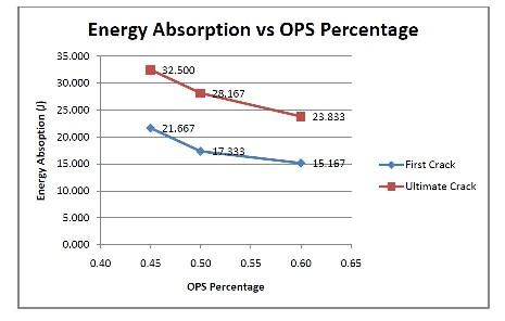
The data also presented in graph relation form as shown in Fig.(1) below. The graph shows the average energy absorption of each OPS percentage specimens for both first crack and ultimate failure, which decrease with increased OPS content.
IJSER © 2012 http://www.ijser.org
International Journal of Scientific & Engineering Research, Volume 3, Issue 11, November-2012 15
ISSN 2229-5518
9.3- Crack Resistance:
Sample Numbers | First Crack Resistance, N/mm2 | Ultimate Crack Resistance, N/mm | Crack Resistance Ratio (Cy) |
0.45/control/1 0.45/control/2 0.45/control/3 | 11.621 15.181 12.859 | 19.368 18.976 21.431 | 0.704 0.690 0.779 |
0.45/60-1/1 0.45/60-1/2 0.45/60-1/3 | 16.374 17.559 24.007 | 39.766 40.135 45.014 | 1.446 1.459 1.637 |
0.45/60-2/1 0.45/60-2/2 0.45/60-2/3 | 24.482 16.286 19.838 | 64.266 46.532 57.034 | 2.337 1.692 2.074 |
0.45/80-1/1 0.45/80-1/2 0.45/80-1/3 | 20.468 19.233 17.186 | 64.327 48.081 51.558 | 2.339 1.748 1.875 |
0.45/80-2/1 0.45/80-2/2 0.45/80-2/3 | 27.664 24.940 24.276 | 94.847 77.938 75.864 | 3.449 2.834 2.759 |
Sample Numbers | First Crack Resistance, N/mm2 | Ultimate Crack Resistance, N/mm | Crack Resistance Ratio (Cy) |
0.50/control/1 0.50/control/2 0.50/control/3 | 11.690 13.092 7.840 | 18.483 17.456 15.679 | 0.708 0.635 0.570 |
0.50/60-1/1 0.50/60-1/2 0.50/60-1/3 | 15.819 14.986 13.832 | 33.898 39.962 31.616 | 1.233 1.453 1.150 |
0.50/60-2/1 0.50/60-2/2 0.50/60-2/3 | 17.433 13.904 24.141 | 47.318 46.368 63.370 | 1.721 1.685 2.304 |
0.50/80-1/1 0.50/80-1/2 0.50/80-1/3 | 19.174 16.038 20.303 | 60.718 46.595 50.756 | 2.208 1.694 1.846 |
0.50/80-2/1 0.50/80-2/2 0.50/80-2/3 | 20.358 34.443 23.080 | 66.890 103.328 69.241 | 2.432 3.757 2.518 |
Sample Numbers | First Crack Resistance, N/mm2 | Ultimate Crack Resistance, N/mm | Crack Resistance Ratio (Cy) |
0.60/control/1 0.60/control/2 0.60/control/3 | 13.374 8.649 7.747 | 17.833 17.299 11.621 | 0.648 0.629 0.423 |
0.60/60-1/1 0.60/60-1/2 0.60/60-1/3 | 15.499 17.765 11.824 | 38.748 38.067 27.588 | 1.409 1.384 1.003 |
0.60/60-2/1 | 29.226 | 63.042 | 2.292 |
IJSER © 2012 http://www.ijser.org
International Journal of Scientific & Engineering Research, Volume 3, Issue 11, November-2012 16
ISSN 2229-5518
0.60/60-2/2 0.60/60-2/3 | 19.930 14.130 | 51.248 42.391 | 1.864 1.542 |
0.60/80-1/1 0.60/80-1/2 0.60/80-1/3 | 21.452 13.702 18.598 | 55.163 38.823 58.594 | 2.006 1.412 2.142 |
0.60/80-2/1 0.60/80-2/2 0.60/80-2/3 | 30.921 22.173 23.080 | 92.762 69.688 63.471 | 3.373 2.534 2.308 |
Tables 8, 9 and 10 show the crack resistance of each specimen for both first crack initiation and ultimate failure. The crack resistance is calculated from (eq.1) while the crack resistance ratio is calculated using (eq.2). For the crack resistance, crack length, crack width, crack depth and the energy absorption were used as parameters. In this analysis, the crack width and the crack length were measured using certain apparatus, while the crack depth is assumed that to be constant
15mm for all the specimens. This is due to the inconsistent crack depth developed along the crack length. From both of the analysis for numbers of blows and energy absorption, the results do hint that the crack resistance of specimens decreases as the OPS content increases. Although the crack resistance is found to have the similar pattern, there is still some inconsistency within the results. Looking at the individual specimen, 0.50/80-2/2, having ultimate crack resistance of
103.328 N/mm2 and higher than the crack resistance of 0.45OPS. The inconsistency may due to several factors; firstly looking at (eq.1), using crack width as one of the parameters, as crack width is very difficult to differentiate using naked-eye. Slight changes of crack width judgment may significantly affect the determination of crack resistance. Another factor that contributed to the inconsistency is the total crack length, as each specimen has different and unique crack length, the results is less predictable. Although the individual results did not show consistency, the average crack resistance for all the crack resistance is calculated and analyzed to provide clearer picture in understanding the crack behavior of specimens.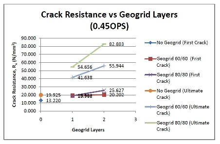
Other than the relation of crack resistance and OPS percentage, the second and third relation can be found is the improvement of crack resistance with geogrid layer and geogrid type. To simplify the understanding of geogrid layer’s effect on the crack resistance, three graphs were plotted as shown below.
IJSER © 2012 http://www.ijser.org
International Journal of Scientific & Engineering Research, Volume 3, Issue 11, November-2012 17
ISSN 2229-5518
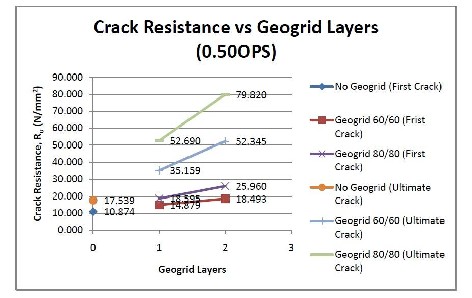
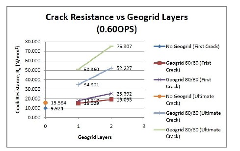
Looking at the three graphs, Fig (2), (3) and (4), the pattern shown is quite similar. They show that at the first crack initiation, specimens reinforced with one layer of geogrid have improvement of crack resistance by 20% to 30% when reinforced with two layers of geogrid. It is obvious that the improvement is quite linear (less) as compared to the ultimate crack resistance. While for the ultimate crack resistance, the crack resistance increases by 30% to 50% when there is an additional layer of geogrid reinforcement. From the results, it can be discussed that the addition of geogrid layers does not contribute much in first crack initiation resistance but does improve the crack resistance for ultimate failure.
IJSER © 2012 http://www.ijser.org
International Journal of Scientific & Engineering Research, Volume 3, Issue 11, November-2012 18
ISSN 2229-5518
From the analysis assumption, the first crack initiation may depend more on the properties on concrete instead of reinforcement. Focus on the specimens with one layer of geogrid and control specimens, the improvement of first crack initiation is much lesser as compared to the ultimate crack resistance improvement. It can be said that the geogrid contribute more toward the ultimate crack resistance.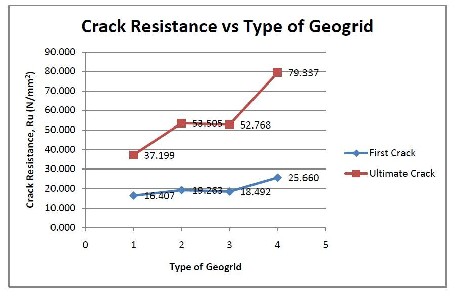
The third relation extracted from the data the performance of geogrid type on the crack resistance. The following graph below shows the relation of crack resistance and geogrid type. The value used in the graph for each geogrid type is the average of all OPS percentage for each type of geogrid. The X-axis in the graph represent the geogrid types; 1 represent reinforcement with one layer of geogrid 60/60, 2 represent reinforcement with two layers of geogrid 60/60, 3 represent reinforcement with one layer of geogrid 80/80 and 4 represent reinforcement with two layers of geogrid 80/80. In the graph, it shows that specimens reinforced with one layer of geogrid 60/60 have the lowest crack resistance (first crack and ultimate) while specimens reinforced with two layers of geogrid 80/80 have the best performance on crack resistance. In addition, looking at the specimens reinforced with two layers of geogrid 60/60 and one layer of geogrid 80/80, the data are almost identical to each other. It can be said that, the specimens reinforced with one layer of geogrid 80/80 have the crack resistance equally to the specimens reinforced with two layers of geogrid.
9.4- Performance Analysis for Geogrid:
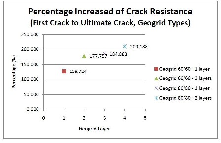
Table (11) and Figure (6) show the performance improvement for each type of geogrid combination, from first crack initiation to ultimate failure. The data above is calculated based on average value for all three OPS percentage, 0.45, 0.50 and 0.60. From the calculation, specimens reinforced with geogrid have their performance to resist impact loading from first crack initiation and ultimate failure increased up to 200%. It indicates that geogrid able to prolong the structural capability of a concrete structure when under impact load. Geogrid improve more on the limit state capability than the serviceability state capability.
IJSER © 2012 http://www.ijser.org
International Journal of Scientific & Engineering Research, Volume 3, Issue 11, November-2012 19
ISSN 2229-5518
Looking at the geogrid layer aspect, specimens reinforced with one layer of geogrid only does not show consistency in performance improvement as specimens reinforced with one layer of geogrid 80/80 has better crack resistance improvement, 184.833% increment if compared with specimens reinforced with one layer of geogrid 60/60 which has only crack resistance improvement of 126.724. This pattern is also applicable to specimens reinforced with two layers of geogrid where specimens reinforced with two layers of geogrid 80/80 have better crack resistance improvement.
Geogrid Type | Geogrid Layer | Average First Crack Resistance (N/mm2 | Average Ultimate Crack Resistance (N/mm2) | Percentage Increased (%) |
0 | 11.339 | 17.683 | 55.941 | |
60/60 | 1 | 16.407 | 37.199 | 126.724 |
60/60 | 2 | 19.263 | 53.505 | 177.757 |
80/80 | 1 | 18.491 | 52.679 | 184.883 |
80/80 | 2 | 25.660 | 79.337 | 209.188 |
9.5- Failure Pattern:
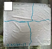
From the experimental observation, there are two types of failure mode. For specimens without
geogrid reinforcement (control specimens), the specimens broke into two pieces at failure. It is observed that during the initial impact loading, the crack developed along the middle of the specimens’ bottom surface area. As the specimens are freely supported only at two sides, hence the impact energy only able to travel through the supported sides. Where else, the stress induced at the unsupported sides and leads to crack development. For the specimens without reinforcement, the specimens will crack first then broke into two pieces at ultimate failure.
IJSER © 2012 http://www.ijser.org
International Journal of Scientific & Engineering Research, Volume 3, Issue 11, November-2012 20
ISSN 2229-5518

a b c
d
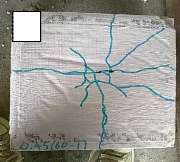
For the specimens reinforced with geogrid, the failure mode is totally different from the first failure mode as mentioned above, where the specimens broke into two pieces at ultimate failure. For geogrid reinforced specimens, the specimens did not break into two pieces at ultimate failure. From the experimental observation, the specimens reinforced with geogrid able to sustain slightly more impact loading before the first crack develop. While for the ultimate failure, the geogrid addition is a great feature in concrete to resist a lot more impact loading, as shown in Fig (7).
a- The data shows that the increment of OPS content in specimen reduces the crack resistance.
b- The additional geogrid layer in the specimen does increase the crack resistance for both first crack and ultimate failure. However, the improvement is not identical for both first crack resistance and ultimate crack resistance. The addition of geogrid layer only improves the first crack resistance by 20% to 30%; while 30% to 50% for ultimate crack resistance. It can be concluded that the addition of geogrid affect more on ultimate crack resistance instead of first crack resistance. However, if compared to the control specimens, the first crack resistance improvement is about 100% to 200%; while the improvement for ultimate crack resistance is up to 500%.
c- For the analysis of crack resistance and geogrid type, the observation founded during the analysis is that, the performance of specimens reinforced with two layers of geogrid
60/60 is almost identical to specimens reinforced with one layer of geogrid 80/80.
IJSER © 2012 http://www.ijser.org
International Journal of Scientific & Engineering Research, Volume 3, Issue 11, November-2012 21
ISSN 2229-5518
211.2-98, American Concrete Institute, Detroit, Michigan, 1998.
2- Ehsan Ahmed, Habibur Rahman Sobuz and Liew Yu Voon, Deflection of Oil Palm Shell (OPS) Aggregate Concrete Beams Under Sustained Loading, Department of Civil Engineering, Universiti Malaysia Sarawak, p. 160-165.
3- D.C.L. Teo, M.A. Mannan, V.J. Kurian and C. Ganapathy, Lightweight Concrete Made From Oil Palm Shell (OPS): Structural Bond and Durability Properties, Building and Environment 42 (2007), p. 2614-2621.
(OPS), Building and Environment 39 (2004), p. 441-448.
ACI Materials Journal, Title no. 102-M28.
IJSER © 2012 http://www.ijser.org