International Journal of Scientific & Engineering Research, Volume 4, Issue 12, December-2013 1798
ISSN 2229-5518
Higher Data Transmission With Higher Channel Isolation And Low Channel Spacing In High Dense WDM System
Mr. Manish saxena, Dr.Anubhuti Khare, Mr.Amit R.Mahire
Abstract— To transmit higher data 10 Gbits/s and above is possible by using of High Dense WDM System. When data is transmitting through such a systems there is possibility of interference of channel with each other so in this paper the we have used two fiber bragg grating as a filter connected back to back to each other in which first fBG uniform apodization profile and second FBG has three apodization profile i.e uniform apodization profile, guassian apodization profile, tanh (hyperbolic tangent) apodization profile to overcome channel interference problems and higher side lobe reduction to avoid distortion. The HDWDM system used here for 2.5 Gbits/s to 10.52
Gbits/s data with channel spacing of 50 Ghz,25 Ghz. We have used two simulation in first simulation we used 4 separate transmitter with passive power combiner to combine 4 signals and in second simulation we used 8 channel WDM transmitter with multiplexer. In which second simulation is best and there is higher data transmission i.e 10.52 Gbits/s and higher channel isolation with lower channel spacing of
25 Ghz.
Index Terms— Apodization Profile,Channel spacing, Fiber Bragg Gratting Filter,Higher Data Rate,Optical Fiber,Simulation Scheme,High
Dense W DM
1 INTRODUCTION
In single optical fiber link includes one transmitter, optical fiber as a channel and one receiver maximum 10 Gbits/s data transmission is possible but above 10 Gbits/s data transmis-
to optical fiber of 40 km and has core effective area of 80 µm2
,attenuation α of 0.2 db/km, dispersion of 16 ps/nm/km.
.
sion is not possible. So we adopt high dense wdm system in which maximum data can be send using multiplexing tech- nique over single fiber. we have used two simulation using optisystem 11 simulation software. In first simulation we used power combiner which is passive network to collect the sig- nal from 4 transmitter and in second and in second simulation we have used wdm transmitter. To send information with higher data we adopt wdm network as well as there should not be interference of signal we used low channel spacing of
50 Ghz and 25 Ghz and using two FBG filter connected one by one to each other we have utilize apodization profiles such as uniform apodization profile, guassian apodization pro- file,Tanh (hyperbolic tangent) profile.[1],[2],[3],[4].
————————————————
• Mr. Manish saxena Assist Prof. (EC Dept.) Bansal Institute of Science and
Technology, Bhopal (India),manish.saxena2008@gmail.com
• Dr.Anubhuti Khare, Associate Proff.,Dept. of EC, UIT RGPV, Bhopal,
MP, India, anubhuitkare@gmail.com
• Mr.Amit R.Mahire PG student at Bansal Institute of Science and Technol-
ogy, Bhopal(India),+918275102143, amit.mahire@gmail.com
2. SYSTEM SIMULATION SETUP
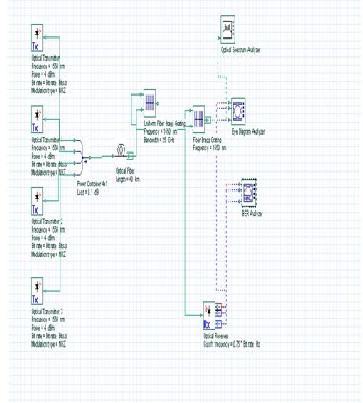
We have used simulation software optisystem 11 and carried two simulations. In both kind of simulation our aim to send the information with high data rate with low channel spacing and higher side lobe suppression of signal. The first simula- tion scheme shown in figure 1 consist of transmitter, power combiner, optical fiber,Two FBG filter connected one by one to each other, optical receiver and visulizers to get the result like optical spectrum analyzer, eye diagram analyzer, BER analyz- er. We have used 4 optical transmitter having signal wave- length of 1550 nm of power 4 dbm and signal is modulated by NRZ format all signals are collect by power combiner and fed
IJSER © 2013
Fig.1.Four channel Simulation scheme with NRZ modula- tion and Different Data Rates like 2.5 Gbits/s and 10.52
Gbits/s
http://www.ijser.org
International Journal of Scientific & Engineering Research, Volume 4, Issue 12, December-2013 1799
ISSN 2229-5518
simulation scheme [1],[2],[3],[4],[5],[6],[7].
The output of fiber is fed to two FBG filter in which first FBG filter has Uniform apodization profile and second FBG has three different apodization profile such as Uniform apodi- zation profile,Guassian apodization profile and Tanh (hyper- bolic tangent) profile. The FBG filter output is given to optical receiver has cut off frequency of 0.75 x Bit rate in Hz and result is displayed on visulizers optical spectrum analyzer, eye dia- gram analyzer, BER analyzer. In second simulation scheme shown in figure 2, we have make changes in transmitter on- ly.[1],[2],[3],[4],[5],[6],[7].
3. RESULTS
Our main to transmit information with higher data rates, low channel spacing and side lobe reduction. We have utilize High Dense WDM network for higher data transmission, we transmit the data with 2.5 Gbits and 10.52 Gbits/s data rate with channel spacing of 50 Ghz and 25 Ghz for both simula- tion scheme. The results for simulation first are as follows. Table-1-Bit Error Rate for 2.5 Gbits/s of channel spacing 50
GHZ & 25 GHZ
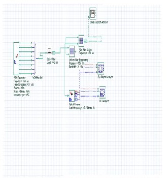
Table-2-Bit Error Rate for 10.52 Gbits/s of channel spacing 50
GHZ & 25 GHZ
IJSER
Fig. 2.Eight channel Simulation scheme with NRZ modula- tion and Different Data Rates like 2.5 Gbits/s and 10.52
Gbits/s
The scheme consist of 8 channel WDM transmitter having signal wavelength of 1550 nm with 4 dbm power and NRZ format sig- nal. All 8 channels are multiplexed by multiplexer and output of multiplexer is fed to optical fiber having 40 km length has core effective area of 80 µm2 ,attenuation α of 0.2 db/km, dispersion of
16 ps/nm/km. The output of fi ber is given to two FBG filters in which first FBG filter has Uniform apodization profile and se- cond FBG has three different apodization profile such as Uniform apodization profile,Guassian apodization profile and Tanh (hy- perbolic tangent) profile. The FBG filter output is given to optical receiver has cut off frequency of 0.75 x Bit rate in Hz and result is displayed on visulizers optical spectrum analyzer, eye diagram analyzer, BER analyzer. When we compare results of both simu- lation scheme second simulation scheme has best result than first
Fig.3.Bit Error Rate for 2.5 Gbits/s of 25 GHZ channel spac- ing for Uniform Apodization profile
IJSER © 2013 http://www.ijser.org
International Journal of Scientific & Engineering Research, Volume 4, Issue 12, December-2013 1800
ISSN 2229-5518
Table 4-Bit Error Rate for 10.52 Gbits/s of channel spacing 50
GHZ & 25 GHZ
Channel Spacing | Uniform | Gaussian | Tanh |
50 GHZ | 6.26731e-010 | 6.79464e-005 | 7.86064e-010 |
25 GHZ | 8.52162e-010 | 6.64693e-005 | 1.06044e-009 |
Fig. 4.Bit Error Rate for 10.52 Gbits/s of 25 GHZ channel spac- ing for Tanh (Hyperbolic Tangent) Apodization profile.
The table no.1 shows bit error rate for 2.5 Gbits/s of channel spacing 50 GHZ & 25 GHZ and figure 3 shows graph for BER for 25 Ghz channel spacing. From table no.1 we can observe that there is low BER for uniform apodization profile of 50
Ghz channel spacing i.e. 0.000266204 and there is low bit error rate for Tanh apodization profile which is 0.000266387 of 25
Ghz channel spacing. Both BER for 50 Ghz and 25 Ghz chan- nel spacing are low but we can adopt BER of lower channel spacing of 25 Ghz but the eye diagram is not clear for data rate 2.5 Gbits/s and for data rate 10.52 Gbits/s we can observe the table no.2 and figure no.4 which shows that there is low bit error rate for apodization profile 1.85151e-008 and Tanh apodization profile has lower BER which is 1.85985e-008.So uniform apodization profile as well as Tanh apodization pro- file are best for higher reduction of side lobes for higher data rate transmission of 10.52 Gbits/s data rate.But there is low bit error rate in simulation scheme second than simulation scheme first which is shown as follows.[1],[2].
Table-3-Bit Error Rate for 2.5 Gbits/s of channel spacing 50
GHZ & 25 GHZ
Fig.5.2.5 Gbits/s, 25 Ghz 8 channel WDM System with Power Spectrum,Eye Diagram,FBG Filter with Uniform Apodization Profile
IJSER © 2013 http://www.ijser.org
International Journal of Scientific & Engineering Research, Volume 4, Issue 12, December-2013 1801
ISSN 2229-5518
4. CONCLUSION
It is clear that second simulation scheme is best than first sim- ulation scheme. Our aim to transmit information with high data rates which is not possible in case of single transmitter, single optical fiber link High Dense WDM System to send in- formation with higher data rates and higher channel isolation with low channel spacing and higher side lobe reduction. when we used second simulation scheme then from all results like low bit error rate, clear opening of eye diagram for both data rates i.e 2.5 Gbits/s and 10.52 Gbits/s but our aim to transmit information with higher data rates so 10.52 Gbits/s is used in second simulation scheme because we can adopt two apodization profile i.e uniform apodization profile and Tanh (hyperbolic tangent) apodization are best for low chan- nel spacing and higher side lobe reduction of signal but for 2.
5 Gbits/s only uniform apodization profile is best for low channel spacing and higher side lobe reduction of signal.In first simulation scheme eye diagram for 2.5 data rates is not clear and BER values are higher for both data rates i.e 2.5
Gbits/s and 10.52 Gbits/s and as compared to second simula- tion scheme. So second simulation scheme is best for sending information with data rate, higher channel isolation and high- er side lobe reduction than first simulation scheme.
REFERENCES
1] Manish Saxena, Dr.Anubuti Khare, Amit Mahire“High Channel Isola- tion Using Two FBG Filter Connected Back to Back For High Dense WDM System.” Published in “International Journal of Electronics & Communi- cation Technology” ISSN : 2230-7109 (Online) | ISSN : 2230-9543 (Print), Vol. 4, Issue 1, Jan - March 2013.
[2] Manish Saxena, Dr.Anubuti Khare, Amit Mahire “Comparative Analysis For Higher Channel Isolation Using Single FBG Filter And Two FBG Filter Connected One After One For High Dense WDM System.” Published in “In- ternational Journal of Electronics & Communication Enginnering & Tech- nology” ISSN : 0976-6472 (Online) | ISSN : 0976-6464 (Print), Vol. 4, Issue
2, March – April 2013.
[3] O. Ozoliņ, Ģ. Ivanovs Realization of ptimal FBG Band–Pass Filters for High Speed DWDM Journal of Electronics and Electrical Engineering,
2009. No. 4(92) ISSN 1392 – 1215
Fig. 6.10.52 Gbits/s , 25 Ghz 8 channel WDM System with power Spectrum, Eye Diagram, FBG filter with Tanh apodiza- tion profile
The table no.3 shows bit error rate for 2.5 Gbits/s of channel spacing 50 GHZ & 25 GHZ in which we can observe low bit error rate for uniform apodization profile i.e. 2.64972e-311 for
25 Ghz channel spacing with 2.5 Gbits/s data rate and from table no.4 we observe that low bit error rate for Tanh (hyper- bolic tangent) apodization profile which is 1.06044e-009 for 25
Ghz channel spacing with 10.52 Gbits/s data rate and eye dia- gram for both apodization profile is clear and peak power transmission occur keeping signal wavelength which is 1550 nm uniform apodization profile and Tanh (hyperbolic tan- gent) apodization profile are best for higher side lobe reduc- tion and there is higher channel isolation and sending of in- formation with higher data rate is possible because of low bit error rate in second simulation scheme.[1],[2].
[4] Agrawal G. Nonlinear Fiber Optics (Third Edition) //Academic
Press. – 2001.
[5] Pfennigbauer M., Winzer P. J. Choice of MUX/DEMUX filter char- acteristics for NRZ, RZ, and CSRZ DWDM systems Light wave Tech- nology. – 2006. –No. 24(4), -P. 1689 – 1696
[6] Bobrovs V., Ivanovs G. Parameter Evaluation of a Dense Optical Net- work Electronics and Electrical Engineering. –2006. – No.4 (25). – P. 33-37. [7] Kashyap R. Fiber Bragg grating // Academic Press. – 1999.
IJSER © 2013 http://www.ijser.org