The research paper published by IJSER journal is about Heat Transfer Enhancement by Nano Structured Carbon Nanotube Coating 1
ISSN 2229-5518
Heat Transfer Enhancement by Nano Structured
Carbon Nanotube Coating
Sujith Kumar C. S, S. Suresh, Rajiv K
—————————— ——————————
engineering in National Institute of Technology, Tiruchirappalli, India, PH -
+91-7200345512. E-mail: krishnakumarrajiv@yahoo.co.in
EAT transfer enhancement is an extensive research area, in order to increase the efficiency of energy management. There are several ways to enhance the
heat transfer characteristics, which can be mainly classified into active and passive techniques [1]. Active techniques rely on external power source, such as electronic or acoustic fields and surface vibration. Most of the active techniques are abstruse and intractable with the surrounding. While passive techniques include surface coating, intrinsic fins, surface roughness and change of nanofluids. The passive techniques help us to overcome the limitations faced by the active techniques.
Nowadays there is a huge development in the field of passive heat transfer. Among the different passive techniques present, surface coating seems to the most effective one. Surface coating can be macro structured, micro structured and nano structured coatings. The commonly formed structures using nano structured coatings are nano- porous and nano-finned structure [1], [2], [4], [6], [7], [13]. The recent advances in the field of micro and nanotechnology have led to the development of efficient methods for heat transfer enhancement using nano-porous and nano-fins which are expected to give unique heat transfer potential and more efficient than the existing techniques. Surface coating giving nanostructured coating is the most preferred method due to the following 5 reasons.
————————————————
![]() Sujith kumar C S is currently pursuing Phd in Mechanical Department in
Sujith kumar C S is currently pursuing Phd in Mechanical Department in
National Institute of Technology, Tiruchirappalli, India,, PH-+91-
8220867692. E-mail: sujithdeepam@gmail.com
![]() S Suresh is currently working as Assistant professor in Mechanical
S Suresh is currently working as Assistant professor in Mechanical
Department in National Institute of Technology, Tiruchirappalli, India,, PH-
+91-9842483638. E-mail: ssuresh@nitt.edu
![]() Rajiv K is currently pursuing masters degree program in Thermal power
Rajiv K is currently pursuing masters degree program in Thermal power
Surface area effect: The ratio of surface area to volume will increase with the decrease in size of the particle. So for the same volume of micro structured and nano structured coating, nano structured coating will have more surface area. So heat transfer rate will be substantially more for the nano structured coating. Vertically aligned CNT will act as Nanofins and that increase total surface area there by a substantial increase in heat transfer will take place.
Pressure drop: In the case of micro channels, pressure drop is the major problem. This will be further enhanced when we are going for surface coating using micro structure. When we are using nano structure the coating thickness will be negligible compared with the size of micro channel. So the pressure drop due to this surface coating is negligible. Capillary rise: This effect is more dominant in micro and nano-porous structured coating because the small pores can act as capillary tubes. Capillary rise increases the local turbulence there by enhances the heat transfer.
Contact time: Due to the surface area effect, contact time will
be more for nano structured coating. So water can take more
heat from the surface.
Contact angle: Nanostructured surfaces also yield lower static
contact angle and enhanced film dynamics resulting in a
noticeable enhanced heat transfer behavior. The effect of
multiple stream spacing on film morphology and heat
transfer phenomena in nanostructured surfaces is also
presented.
Various coating techniques are available for coating
nano porous and nano fins over the surface. Nano porous
coatings are usually obtained by using Spray pyrolysis [1],
thermal spray [4], [6], [13] and electro deposition [11]. Nano
fins are obtained by coating CNT over the surface. The
commonly employed technique for CNT coating is Chemical
IJSER © 2012 http://www.ijser.org
The research paper published by IJSER journal is about Heat Transfer Enhancement by Nano Structured Carbon Nanotube Coating 2
ISSN 2229-5518
Vapour Deposition (CVD) [2], [12]. Other techniques like dip coating with the help of fusion material [14] and coating
A rotameter is connected to the test section to measure the
with the hel
study, we ha
as it is a vi
minimum co
The sche shown in Fi steel (Shown make Vijay cooling unit the stainless prevented b gaskets wer the reservoi rotameter ( rate 600 LPH
Fig 1. Schematic of experimental setup
mocouples in the test
er which is in turn
s the instantaneous
was selected as the was polished in the ake the surface even.
. Fine polishing of the of grade 1 to 4. Then
h acetone for 2 hours. in acetone for 2 hours mpurities. The coating T was taken for 20 ml as properly dispersed
g the mixture for 4
) is mixed with 2 ml
a pump. The fluid after passing through the heated test section flows through a riser section and then through the cooling unit which is a radiator and finally it is collected in the reservoir. The test section is heated using a heater which is an aluminium block which is heated using cartridge heater (heating capacity 750W). Cartridge heater is connected to an auto transformer, by which heat flux can be varied by varying the voltage. One dimensional heat transfer was maintained with the help of insulation material. Two K –type thermocouples with 5mm outer diameter are placed at the entrance and the exit to measure the inlet and exit temperature. Four thermocouples connected so that it gives the bulk temperature of fluid. Four thermocouples are connected so that they give the surface temperature of substrate. All thermocouples are K type with outer diameter
1mm and calibrated using constant temperature bath. The pressure drop across the test section is measured using a U tube manometer with mercury as the working fluid.
isopropyl alcohol to form a paste. First the omegabond
coating was applied on the plate by brush coating. Then the
coated surface was kept under a 1000 W bulb. It produces a
temperature of about 160ºC on the surface. While the coating
is getting heated CNT coating was applied on the surface by
spray coating. Then the coated plate was kept at 150ºC for six
hours for curing to get a stable coated surface.
Morphological and topographical features of coating are done using Tungsten gun Scanning Electron Microscope (Make –HITACHI, Model- S-300H, and Magnification 60,000
X). Hardness of the coated surface is compared with uncoated surface using Rockwell hardness testing apparatus. Calibration of the test section was conducted under both laminar and turbulent conditions. Heat transfer and pressure drop studies were conducted with and without the coating.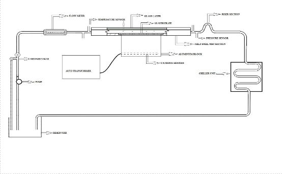
The research paper published by IJSER journal is about Heat Transfer Enhancement by Nano Structured Carbon Nanotube Coating 3
ISSN 2229-5518
![]()
respectively, for parallel plates with constant wall heat flux can be calculated as:![]()
![]()
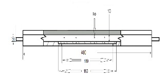
Fig. 2. Schematic of test section
Here we have coated CNT over the SS 304 substrate using Omegabond 200 adhesive. The morphological and topographical are shown in fig. 3. From the SEM image, we can conclude that, a uniform coating over the substrate is obtained. The hardness test was conducted in Rockwell hardness testing apparatus with diamond cone indenters. HRC values were taken from four locations of both coated and uncoated substrates. The average value for the uncoated substrate was about 29 and that of the coated substrate was
26. Even though the hardness obtained for the coated substrate was less than that of the uncoated one, the reduction in hardness is very low. So the coating obtained is stable.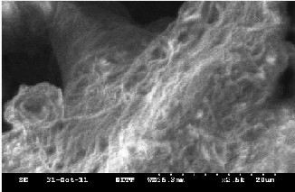
Fig. 3. SEM image of the coated substrate
To validate the experimental setup, experiments were conducted with pure water in the test section with Reynolds number ranging from 500 to 2500. The total length of the test section is 0.38 m and the entrance length of the test section is
0.1 m. The width of the test section is very large compared to its height. So the entry length for parallel plates can be applied to this case.
According to Kakac and Yener (1995), the laminar hydrodynamic and thermal entry lengths, Lh and Lt![]()
![]()
For a Reynolds number of 1000 the value of Lh is about
0.2 m and the thermal entry length is 1.154 m. So the test
section we have created has a hydrodynamically and
thermally developing region at the region of heat transfer. So
the equation that can be used is taken from [16]![]()
![]()
![]() (3)
(3) ![]() (4)
(4)
The entrance length for turbulent flow is 1/4th of that of laminar. So the flow in the turbulent region is hydrodynamically fully developed.
Nusselt number for fully turbulent region is given by![]()
![]() (5)
(5)
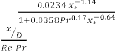
For pressure drop studies, experiment was conducted under isothermal conditions. The experimental values were compared to theoretical values. The equation for pressure drop in hydrodynamically and thermally developing region is given by the equation taken from [17].![]()
![]()
![]()
![]()
![]() (6)
(6) ![]() (7)
(7)
![]()
![]()
![]() (8)
(8)
The pressure drop study was carried out under the isothermal condition, without the application of heat. The pressure difference from the U tube manometer was measured by the formulae.![]()
![]()
![]() (9)
(9)
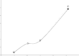
The experimental and the theoretical values are compared to give the results. The pressure drop studies were only conducted in the laminar region of flow. The graphs of the results are indicated in fig. 4 & 5. As there is not much difference between the theoretical and the experimental values obtained, the test section is considered to be valid.
IJSER © 2012 http://www.ijser.org
The research paper published by IJSER journal is about Heat Transfer Enhancement by Nano Structured Carbon Nanotube Coating 4
ISSN 2229-5518
heat can be transferred to water from the heater after the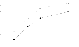
26 application of coating.
24
22 7500
20 7000
18
6500
16
6000
14
5500
12
10
0 500 1000 1500 2000 2500 3000
![]()
Re
Reynolds number vs Nu (Actual) Reynolds number vs Nu (Theoretical)
Fig. 4.Validation based on Nu number
5000
4500
4000
0 500 1000 1500 2000 2500 3000
![]()
Re
Reynolds numberHeat flux( without coating) vs Heat flux without coating
Reynolds numberHeat flux( without coating) vs heat flux with coating
1000
800
600
400
200
0
400 600 800 1000 1200 1400 1600
![]()
Re
Reynolds number vs Pr drop (Theoretical) Reynolds number vs Pr drop (actual)
Fig. 5. Validation based on Pressure drop
3500
3000
2500
2000
1500
1000
500
0
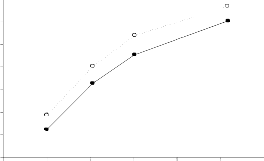
Fig. 6. Heat flux comparison
0 500 1000 1500 2000 2500 3000
![]()
Re
Reynolds number vs Pr drop without coating
Reynolds number vs Pr drop with coating
Heat transfer comparison of the coated and uncoated stainless steel substrates were carried out under constant heat flux condition. The flow rate was changed by means of the bypass valve. The flow rate readings were noted using the rotameter. Thermocouples were used to note temperatures for the flow rates 100, 200, 300 and 500 LPH. Based on these values the heat transfer characteristics were noted.
Heat flux enhancement of coated substrate over the uncoated one is shown in the fig. 6. In the graph the heat flux values were plotted with the corresponding Reynolds number values. Heat flux is found out by dividing the heat taken by water by the area. The heat flux with coating shows a considerable increase when compared to the heat flux without coating. This is due to the fact that more amount of
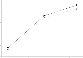
Fig. 7. Pressure drop comparison
Fig. 7. Shows the pressure drop comparison. There is only a small difference in the pressure drop values. The difference in the pressure drop values is mainly due to the increase in roughness of the surface. The difference becomes more prominent in the turbulent zone as the roughness increases the turbulence created.
The effect of CNT coating on a stainless steel substrate on the heat transfer and pressure drop characteristics were studied in fully developed turbulent and developing laminar flow conditions through a rectangular channel with constant heat flux condition were investigated in the experimental study. The conclusions obtained are
The use of CNT coatings on the surface enhances the
heat flux when compared to an uncoated surface. This is
IJSER © 2012 http://www.ijser.org
The research paper published by IJSER journal is about Heat Transfer Enhancement by Nano Structured Carbon Nanotube Coating 5
ISSN 2229-5518
mainly due to the enhancement in surface area and the increase in the roughness on the surface causing local turbulence.
The use of CNT coatings on the surface results in heat
flux enhancement without much increase in the pressure drop. The heat flux enhancement is mainly due to the increase in the convective heat transfer and the increase in the area of contact.
The authors would like to thank Dr.P. Veeramani, senior engineer at Central Electrochemical Research Institute (CECRI), Karaikudi, India and Prof J. Sarangan, Head of Department of Mechanical Engineering, NIT Tiruchirappalli for their helpful discussion.
6. REFERENCES
[1] S.Kalaiselvam, M.S.Gugan, E.Kuraloviyan, R.Meganathan, A Niruthiya Priyan and M.R. Swaminathan “Experimental investigation of anodized/ spray pyrolysed nanoporous structure on heat transfer augmentation”, Journal of Thermal Science Vol 18,
358-363, 2009.
[2] Wei Lin, Rongwei Zhang, Kyoung-sik Moon, and C.P.Wong “Synthesis of High-Quality Vertically Aigned Carbon Nanotubes on Bulk Copper Substrate for Thermal Management”, IEEE Vol. 33
No. 2, 370-376, 2010.
[3] J. H. Park, J. S. Moon, J. H. Han, A. S. Bendinsky and J. B. Yoo “Effect of binders and organic vehicles on the emission properties of carbon nanotubes paste”, Diamond and related materials, 1463-
1468, 2005.
[4] Histoshi Asano, RyoheiTomia, RyotaShigehara and Nobuyuki Takenaka “Heat Transfer Enhancement in Evaporation by Thermal Spray Coating”, International Symposium on Next-generation Air Conditioning and Refrigeration Technology 17-19, Tokyo, Japan, 2010.
[5] Zhidong Han and Alberto Fina “Thermal conductivity of carbon nanotubes and their polymer composites: A revie w”, Progress in polymer science 36, 914-944, 2011.
[6] Peixue Jiang, Zhan Wang, Zepei Ren and Buxwann Wang,“Forced Convection Heat Transfer in a Porous Plate Channel”, Journal of Thermal Science , vol.6, No.3, 1997.
[7] Mohammad Sohail Sarwar, Yong Hoon Jeong and Soon Heung Chang, “Subcooled flow boiling CHF enhancement with porous surface coatings”, International journal of heat and mass transfer, 3649-
3657, 2007.
[8] Shiren Wang and Jingjing Qiu, “Enhancing thermal conductivity of glass fiber/polymer composites through carbon nanotubes incorporation”, composites : part B 41, 533-536, 2010.
[9] Y. Tzeng, Y. Chen, N. Sathitsuksanoh and C. Liu, “Electrochemical behaviours and hydration properties of multi wall carbon nanotubes coated electrodes in water”, Diamonds and related materials 13, 1281-1286, 2005.
[10] Chi-Chuan Wang and Chang-Tsair Chang, “Heat and mass transfer for plate fin and tube heat exchangers, with and without hydrophilic coating”, International Journal of Heat and Mass Transfer
41, 3109-3120, 1998.
[11] Y.L. Yang, Y.D. Wang, Y. Ren and C.S. He, J.N. Deng, “Single walled carbon nanotubes reinforced copper composite coatings prepared by electrodeposition under ultrasonic field”, Material Letters 62, 47-50, 2008.
[12] N. Singh, V. Sathyamurthy, W. Peterson, J. Arendt and D. Banerjee, “Flow boiling enhancement on a horizontal heater using carbon nanotubes coatings”, International Journal of Heat and Fluid Flow 31,
201-207, 2010.
[13] Hitoshi Asano, Ryohei Tomita, Ryota Shigehara and Nobuyuki Takenaka, “Heat transfer enhancement in evaporation by thermal spray coating”, International Symposium on next generation Air conditioning and refrigeration technology, 17-19, 2010.
[14] Young Il Song, Gil Yong Kim, Ha Kyu Choi, Hee Jin Jeong, Ki Kang Kim, Cheol Min Yang and Seong Chu Lim, “Fabrication of carbon nanotubes field emitters using a dip coating method”, Chemical Vapor Deposition 2006, I2, 375-379, 2006.
[15] Adrian Bejan, Convection heat transfer, Third edition, John Wiley & Sons Publication, 2004
[16] http://www.coolingzone.com/library.php?read=489
IJSER © 2012 http://www.ijser.org