International Journal of Scientific & Engineering Research, Volume 6, Issue 3, March-2015 132
ISSN 2229-5518
Heart Beat Charger
Vikas Chib
Model Institute of Engineering and Technology, Jammu
Abstract— A stethoscope is a medical device for listening to the sound of heart and breathing in our body. The commonly used stethoscope is an acoustic stethoscope. The disadvantage of acoustic stethoscope is that the sound level is very low and this stethoscope is not very suitable to use in noisy environment, that's why in our research we use Electronic stethoscope electronically amplifies body sounds. In this device, sound waves from body are converted from analog to electrical signals and then amplified. The primary aim of this paper is to make a device which amplifies the output of the electronic stethoscope and that amplified signal is used to charge our mobile phones. In this paper we discussed the method, to using heartbeat for mobile charging.
Index Terms— Amplifier, Filters, Murmurs, Pressure, Sensors, Stethoscope, Systole, Transducer.
—————————— ——————————
1 INTRODUCTION
stethoscope is a medical device for listening to the sound of heart and breathing in our body. By using the stethoscope the doctor can detect the problem of
the heart and lung of the patient. There are two basic types of stethoscope. It is acoustic stethoscope and electronic stethoscope. Acoustic stethoscope is operating on the transmission of sound captured by the chest piece with two air tubing to the listener ears. The chest piece has two sides, a diaphragm and a bell. The diaphragm creates high frequency sounds and bell creates low frequency sounds. The disadvantage of acoustic stethoscope is that the sound level is very low and this stethoscope is not very suitable to use in noisy environment as well as to detect internal sounds of babies as they are very low. But electronic stethoscope overcomes the sound levels by electronically amplifying body sounds. However, amplification of stethoscope contact aircraft, and component cut offs limit electronically amplified stethoscopes, overall utility by amplifying by amplifying mid-range sounds, while simultaneously attenuating high and low frequency range sounds. Currently, a number of companies offer electronic stethoscopes. Electronic stethoscopes require conversion of acoustic sound waves to electrical signals which can then be amplified and processed for optimal listening. Unlike acoustic stethoscopes, which are all based on the same physics, transducers in electronic stethoscopes vary widely. The simplest and least effective method of sound detection is achieved by placing a microphone in the chest piece. This method suffers from ambient noise interference and has fallen out of favour. Another method, used in Welch- Allyn's Meditron stethoscope, comprises placement of a piezoelectric crystal at the head of metal shaft, the bottom of the shaft making contact with a diaphragm 3M also uses piezoelectric crystal placed within foam behind a thick rubber-like diaphragm Thinklab's Rhythm 32 inventor, Cleve Smith uses an Electromagnetic Diaphragm with a conductive inner surface to form a capacitive sensor.
————————————————
• Vikas Chib is currently pursuing B.E. program in Electronics and
Communication from Model Institute of Engineering and Technology,
Jammu, India, PH-09622203242. E-mail: vikaschib28@gmail.com.
This Diaphragm responds to sound waves identically to a conventional acoustic stethoscopes, with the change in electric field replacing changes in air pressure. This preserves the sound of an acoustic stethoscope with the benefits of amplification.
In this paper we explained our idea to design a heart beat
charger with the help of stethoscope, sensors, filters, pre-
amplifier, rectifier etc. Here, the sensors are used in the
chest piece of an electronic stethoscope to convert body
sounds into electronic signal. These electronic signals often
pick up the noise, therefore it is important to filter that signal and only produce the sound of interest. The output of the of the filter get amplified with the help of amplifier circuit and this output is given to the rectifier to remove the ac components from the input signal. The output(5-6V) of the rectifier is ready for charging.
2. PHYSIOLOGY OF THE HEART
The human heart is composed of four chambers, see Figure
1.1 The upper chambers are called atria and the lower
chambers are called ventricles. The heart muscle squeezes blood from chamber to chamber. At each squeeze, the heart valves open when each chamber contracts to let blood through to the next chamber and close to prevent backflow of blood when the
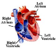
Fig 1.1 Four Chamber of Heart
IJSER © 2015 http://www.ijser.org
International Journal of Scientific & Engineering Research, Volume 6, Issue 3, March-2015 133
ISSN 2229-5518
contraction is completed. In this way, the valves keep blood moving as efficiently as possible through the heart and out to the body.
2.1 Heart Sounds


The sound heard during auscultation are called the first (S1) and the second (S2) heart sounds respectively, shown in Figure 1.2. The first 2 heart sounds (S1 and S2) are “normal” heart sounds that should be detectable in most patients. The S1 sound represents the near-simultaneous closure of the mitral and tricuspid valves, after blood has returned from the body and lungs [9]. This is the start of systole. The S2 sound represents the near-simultaneous closure of the aortic and pulmonary valves as blood exits the heart to the body and lungs . This is the end of systole and the beginning of diastole.
Fig 1.3. Heart Murmurs.
3 DESIGN AND ANALYSIS


The first stage of the is to develop a model circuit for the stethoscope which is capable of catching the internal sounds of the body ,filtering out unwanted signals, amplify the required signal and give the conditioned signal for the output.


STETHOSCOPE MICROPHONE FILTER
OUTPUT TO
MOBILE


RECTIFIER

Fig 1.4. Block Diagram of the Circuit
AMPLIFIER
Fig 1.2. Heart Sounds
2.2 Heart Murmurs
A heart murmur is an abnormal sound of the heart that is usually caused by alular dysfunctions which occurs when a valve does not work the way it should.10 Murmurs can occur in either systole or diastole, as seen in Figure 1.3. Systolic murmurs occur between the first and second heart sound (S1 and S2), and diastolic murmurs occur between the second and first heart sounds (S2 and S1). The severity of systolic murmurs 10 is determined by grades, with grade
1 being the lowest in amplitude and 6 being the highest. Murmurs with higher amplitudes can sometimes be heard without a stethoscope. Most murmurs are not serious, and many childhood murmurs disappear with time.
The sensors are used in the chest piece of an electronic stethoscope to convert body sounds into an electronic signal. These sensors have a high-frequency response that is quite adequate for body sounds. Rather, it is the low- frequency region that might cause problems . The microphone is an air coupled sensor that measure pressure waves induced by chest-wall movements. The microphone in the acoustic sensor needed to be biased in order for proper operation. In addition the output of the microphone is on order of millivolts, which is relatively small in magnitude as compared for the input for rectifier. therefore a bias and amplifier circuit was designed and implemented to the interface with the rectifier. the figure 1.5. below give the schematic of the completed circuit.
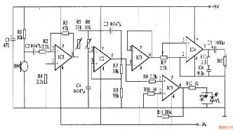
Fig 1.5. Bias and Amplifier Circuit.
The typical operating range for the microphone was 2V with a maximum rating of 10V. The pickup sensor is composed of microphone BM and R1. The Pre-amplifier is composed of integrated operational amplifier and resistors
IJSER © 2015 http://www.ijser.org
International Journal of Scientific & Engineering Research, Volume 6, Issue 3, March-2015 134
ISSN 2229-5518
R2-R5. The low-pass filter amplifier is composed of operational amplifier integrated circuit IC2 and transistor R6-R8, Capacitor C3,C4, The cut-off frequency is slightly larger than 100Hz. The Buffer amplifier is composed of integrated operational amplifier circuit IC3.
3.1 Implementation on Hardware
Once the successful simulation of the developed circuit is done and expected results are achieved then the second stage comes i.e. development of a prototype by realization of the virtual circuit on hardware via breadboard and active and passive components. After the development of the prototype, the output of it is verified using oscilloscope.
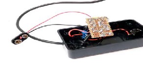
Fig 1.6. Hardware Implementation
4 RESULT
The results of simulation on software achieved were satisfactory as shown in following figures
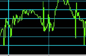
Fig 1.7. Input Response of Microphone
The amplifier circuit was thoroughly tested after it was made. The function generator is connected to the input of the circuit and frequencies were manually swept to test and verify the circuit's frequency response. The following table and plot shows the measured frequency response of the microphone circuit.
Fig. 1.8. Microphone Circuit Frequency Response Results
Fig. 1.9. Microphone Circuit Frequency response
5 CONCLUSION
Nearly all medical personnel actively involved in the treatment and diagnosis of patients use stethoscopes on a daily basis. Stethoscopes are used for pulse measuring, blood pressure monitoring, and diagnosis of cardiovascular, respiratory, and digestive diseases. But we are used this stethoscope for the mobile charging. This is very efficient and modern way to mobile charge. we can charge our mobile phones at any time at any place. This project is our effort towards designing such a device which not only used for to calculate the heartbeat but that heart beat is used for to charge the mobile phones and but is also cost effective and easy to use. we have used the simplest of components known so that the designing of this heart beat charger can be universal and have simulated it. The various advantages of this method are:-
1. This provides the better and efficient way to charge the
mobile phones.
2. It is very easy to be implemented both in terms of
software and hardware.
IJSER © 2015 http://www.ijser.org
International Journal of Scientific & Engineering Research, Volume 6, Issue 3, March-2015 135
ISSN 2229-5518
3. It is rather compact and portable.
4. It is very cost effective.
5. A heart beat can be recorded and analyzed later on.
6. It is method by which we can recharge our mobile phone
anytime and anywhere.
6 ACKNOWLEDGEMENT
This project cannot be considered complete without mentioning Mr. Jamini Sharma HOD of Electronics and Communication department, Model Institute of engineering and technology, Jammu. I wish to
express true sense of gratitude towards his valuable
contribution. I am very grateful to him for
constant encouragement and guidance in the
fulfillment of this activity.
6 REFERENCES
[1] Handbook of Biomedical Instrumentation by R.S. Khandpur, second edition published by Tata-McGraw-Hill publishing company limited.
[2] wikipedia.org/wiki/stethoscope
[3] Digital Stethoscope-A portable, electronic auscultation
device by Michael Wu, Cornell University Electrical and
Computer Engineering.
[4] ukessays-Electronic Stethoscope convert acoustic sound
waves.
IJSER © 2015 http://www.ijser.org