International Journal of Scientific & Engineering Research, Volume 3, Issue 6, June-2012 1
ISSN 2229-5518
Harmonic Modeling of Residential and
Commercial Loads with Unified Power Quality
Conditioner
R.Kameswara Rao, S.S.Tulasiram
Abstract— In this paper simulation models are developed for various nonlinear loads. The different nonlinear loads like personal computer, fluorescent lamp, uninterruptable power supply, adjustable speed drive and power converter are considered. The proposed models are employed for harmonic analysis of a practical system and to design a Unified power quality conditioner (UPQC) to mitigate harmonics in the distribution system. These loads are considered individually and they are taken as loads to the electrical distribution system and evaluated for Total Harmonic Distortion (THD). The analysis of voltage and current harmonics is performed for these loads individually. These models are used for harmonic analysis of typical domestic and commercial loads. Finally THD of the combined loads is analyzed by using all these loads put together. To minimize these harmonics in supply currents, a three Phase Unified Power Quality Conditioner is used. The dynamic model of the UPQC is developed in the MATLAB/SIMULINK environment and the simulation results demonstrating the power quality improvement in the system are represented by FFT analysis.
Index Terms— Distribution system, Unified power quality conditioner (UPQC), Power quality, Total harmonic distortion (THD), harmonic mitigation techniques
—————————— ——————————
he guidelines for Modeling of nonlinear loads commonly used for domestic/ commercial purposes are described in various forms [1]. The voltage distortion caused by the har- monic producing load is a function of both the system imped- ance and the amount of harmonic current injected. The basics of harmonics and the concepts regarding harmonics are taken are described by Arrilliga [2]. There are Different approaches for harmonic analysis of different non-linear loads [3]. The characterization and compensation of harmonics are described by Jose Antinor Pomilio [4]. The recommended practices for harmonic control in power systems are explained IEEE com- mittee [5]. The mere fact that a given load current is distorted does not always mean there will be undue adverse effects on other power consumers [6]. The widespread use of micro- processor-based controls and other sensitive power electronics devices over the past decades has lead power system engi- neers into improving modeling techniques progressively to meet up challenges. In recent years, studies have focused on methods of correctly predicting power quality impact of single
phase nonlinear loads [7]-[8].
It is the objective of the electric utility to supply its custom- ers with a sinusoidal voltage of fairly constant magnitude and
frequency. The generators that produce the electric power generate a very close approximation to a sinusoidal signal. However there are loads and devices on the system which have nonlinear characteristics and result in harmonic distor-
————————————————
R.Kameswara Rao is working as associate professor in JNTU Kakinada, INDIA, E-mail: rkameswara@gmail.com.
S.S.Tulasi Ram is working as professor in JNTU Kakinada, INDIA, E-mail: ramsankara@gmail.com.
-tion of both the voltage and current signals. As more nonli- near loads are introduced within a facility, these waveforms get more distorted.
The planning, design, and operation of industrial and commercial power systems require several studies to assist in the evaluation of the initial and future system performance, system reliability, safety and the ability to grow with produc- tion and operating requirements. The conventional ac electric power systems are designed to operate with sinusoidal vol- tages and currents. However nonlinear loads and electronical- ly switched loads will distort steady state ac voltage and cur- rent waveforms. Periodically distorted waveforms can be stu- died by examining the harmonic components of the wave- forms. Reducing voltage and current waveform distortions to acceptable levels has been a problem in power system design from the early days of alternating current.
The utilization of electrical energy is relying more on the supply of power with controllable frequency and voltages while its generation and transmission take place at nominally constant levels. The discrepancy therefore, requires some form of power conditioning or conversion, normally implemented by power electronic circuitry that distorts voltage and current waveforms. A harmonic-producing load can effect the neigh- boring sensitive loads if significant voltage distortion is caused. The voltage distortion caused by the harmonic- producing load is a function of both the system impedance and the amount of harmonic current injected. The mere fact that a given load current is distorted does not always mean there will be undue adverse effects on other power consumers.
If the system impedance is low, the voltage distortion is usually negligible in the absence of harmonic resonance. However, if harmonic resonance prevails, intolerable harmon- ic voltage and currents are likely to result. In a practical power system the frequency and voltages are deviated from their designated values. The nonlinear characteristics of many sys- tem components produce system harmonics which may de-
IJSER © 2012
International Journal of Scientific & Engineering Research Volume 3, Issue 6, June-2012 2
ISSN 2229-5518
grade the signal transmission in nearby telephone lines. The power quality problems are surging with the proliferation of nonlinear devices which draw non-sinusoidal current wave- forms when supplied by a sinusoidal voltage source. When these devices are present in an electric power system, they cause harmonic distortion of voltages and currents. Indivi- dually, single-phase non-linear load may not pose serious harmonic problem but large concentrations of these loads have the potential to raise harmonic voltages and currents to unacceptable high levels which results in increased neutral currents in four wire system, over heating of distribution sys- tem components and mechanical oscillations in generators and motors. Other undesirable effects are capacitor and insulation failure due to harmonic resonance, unpredictable behavior of installed protection systems, rapid voltage fluctuations and overheating of transformer.
To minimize these harmonics in supply currents Three
Phase Unified Power Quality Conditioner is used. Analysis is
commonly done to predict distortion levels for addition of a
new harmonic producing load or capacitor bank. A dynamic
model of the UPQC is developed and some of the commonly
used loads in the domestic/ commercial systems are modeled in MATLAB/ SIMULINK. The simulation results demonstrat-
ing the power quality improvement in the system are represented by FFT analysis.
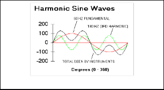
A harmonic of an electrical signal is defined as the content of the signal whose frequency is an integral multiple of the fun- damental system frequency. That is, the third order harmonic will have a frequency of 3 times the fundamental frequency. Fig. 1. Shows the waveform with symmetrical harmonic com- ponents.
and so even-numbered harmonics (2nd, 4th, 6th, 8th, 10th etc) are absent or only minimally present in most AC power systems.
Current Harmonics effect the system by loading the distri- bution system as the waveforms of the other frequencies use up capacity without contributing any power to the load. They also contribute to I2R losses in the system. The Harmonic cur- rents load the power sources such as transformers and alterna- tors. However, current harmonics do not effect the other linear loads in the system. They only impact the loads which are causing them i.e. non-linear loads.
Voltage harmonics are caused by the current harmonics
which distort the voltage waveform. These voltage harmonics
effect the entire system not just the loads which are causing
them. Their impact depends on the distance of the load caus-
ing the harmonics from the power source. If other harmless
loads are connected between the source and harmonics caus- ing loads, these innocent loads will also be affected by the harmonics. Hence, one way of mitigating the effect of harmon- ics is by connecting the harmonics-causing loads as close to
the source as possible in a separate feeder. Another method is by using an isolating transformer between the problem loads and the rest of the distribution system.
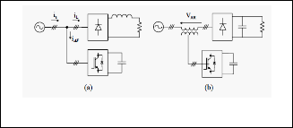
Active harmonic compensation (filtering) method is relatively a new method for eliminating current harmonics from the line. Active filters give good system performance and current har- monics reduction. However, they are based on sophisticated power electronics components and thus they are much more expensive than passive filters. In active filters the basic idea is to inject to the line equal magnitudes of the current/voltage harmonics generated by the nonlinear load and with 180 de- grees phase angle difference so they cancel each other. Three phase active filters are used for high-power nonlinear loads such as ASD and AC/DC converters. Active filters of many configurations have been introduced and improved. Shown in Fig. 2(a) and 2(b), are the fundamental configurations.
Fig. 1. Waveform with symmetrical harmonic components Fig. 2. (a) Shunt active filter (b) Series active filter
Harmonics are undesirable components in the sinusoidal waveform of the AC Power supply. Harmonics affect power quality, equipment life and efficiency. It is necessary to moni- tor the harmonics in any power system. If the harmonics are present, they can be rectified by using suitable methods such as filters. When the non-sinusoidal waveform in question is symmetrical above and below its average centerline, the har- monic frequencies will be odd integer multiples of the funda- mental source frequency only, with no even integer multiples. Most nonlinear loads produce current waveforms like this,
The loads based on power electronic devices generally pol- lute the nearby network by drawing non sinusoidal currents from the source. The rapid switching of electronic devices creates additional Problems. This makes voltages and currents at the point of common coupling (PCC) highly distorted [9]. One of the best solution to compensate both current and vol- tage related problems simultaneously is by using Unified Power Quality Conditioner (UPQC) [10], [11]. According to the controlling structure of UPQC, back to back inverters might have different operations in compensation. For exam- ple, they can operate as shunt and series active filters to simul-
IJSER © 2012
International Journal of Scientific & Engineering Research Volume 3, Issue 6, June-2012 3
ISSN 2229-5518
taneously compensate the load current harmonics and voltage isolation [12].
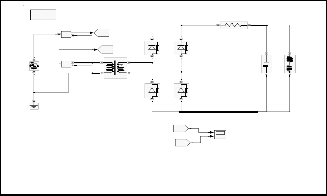
In order to clear the switching oscillation, a passive filter is applied to the output of each inverter. At the output of shunt inverter, high pass secondary order LC or first order RC filter is allocated and at the output of series inverter, low pass second order LC or resonance filter is allocated. UPQC Con- troller provides the compensation voltage through the UPQC series inverter and provides conditioning current through the shunt inverter by instantaneous sampling of load current and source voltage and current. The control strategy is basically the way to generate reference signals for both shunt and series APFs of UPQC as shown in figure 3.
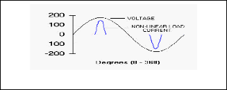
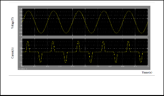
Fig. 5. Non-Linear loads
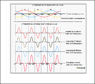
Fig. 3. Simulation model of UPQC
Single phase harmonic producing loads can be broadly classi- fied into three groups. The first group of loads which utilize single-phase capacitive filter Diode Bridge includes loads such as the computers, color television sets, electronic ballast for gas discharge lamps and battery chargers. The second group of loads employs phase-angle voltage controllers in which the major loads falling in this group are heaters, light dimmers, single phase induction motor control and small uninterrupti- ble power supply. The third group of loads is the magnetically ballasted fluorescent lamps.
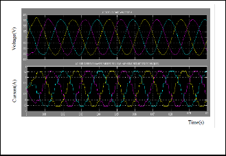
Fig. 6. Current waveforms for Linear and Non-linear loads
A typical PC load model uses SMPS and comprises of a full wave rectifier, a DC storage capacitor C, a diode bridge resis- tance R and a series RFI choke which is represented by an induc- tance L. The Fig 7 shows the personnel computer simulation model and Fig.7a shows Supply Voltage and Current waveforms of Personal computer load. The third and fifth harmonic compo- nents are more dominant in the PC current. The PC's power supply converts the input ac voltage of 50 Hz to a desired direct current output voltage by means of a single-phase rectifier circuit. Generally computer loads produce sharp peaks due to capacitive charging currents drawn by the power supply.
Dis cre te ,
s = 5 e -0 0 5 s
p o we rg u i
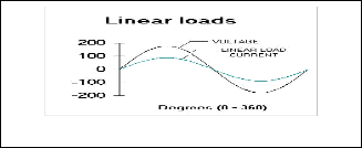
Fig. 4. Linear loads
i [Ii ]
-
Goto1
[Vi ] Goto
R
D1 D3
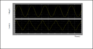
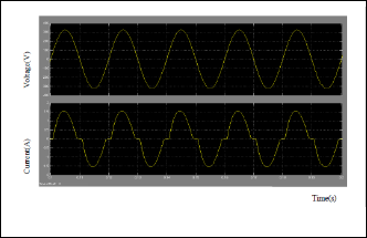
These figures show the voltage and load current waveforms for linear and nonlinear loads. The current drawn by the load is proportional to the voltage and hence these are referred to as linear loads as shown in fig.4. Where as in fig.5 the wave- forms are distorted and not sinusoidal hence these are nonli-
v +
Vs -
1 2
D2 D4
[Vi ] From 1
Scope
c RL
near loads. For the 3-phase system the resultant current in case
of linear loads is zero and in nonlinear loads case, the resultant is the sum of the individual phase currents as shown in fig.6.
[Ii ]
From
Fig. 7. Simulation model of personal computer
IJSER © 2012
International Journal of Scientific & Engineering Research Volume 3, Issue 6, June-2012 4
ISSN 2229-5518
Fig. 7a. Supply voltage and current waveforms of personal com- puter
Generally UPS differs from an auxiliary or emergency power system or standby generator in that it will provide in- stantaneous or near-instantaneous protection from input pow- er interruptions by means of one or more attached batteries and associated electronic circuitry for low power users by means of diesel generators and flywheels for high power us- ers. Figure 9 shows the simulation model for uninterruptible power supply and Fig.9a shows Supply Voltage and Current waveforms of UPS. The on-battery runtime of most uninter- ruptible power sources is relatively short and being typical for smaller units but sufficient to allow time to bring an auxiliary power source on line or to properly shut down the protected equipment.
Compact fluorescent lamps (CFLs) are increasingly being used in residential and commercial buildings because of the desire to reduce electricity usage. CFLs are nonlinear which raises concerns over the widespread use of CFLs. Fluorescent lamps have a negative dynamic resistance behavior which necessitates the use of a ballast to limit the current. Due to the non-linear characteristics of the electronic ballast, the CFLs will inject harmonic currents into the distribution system. The overall effect of these harmonic currents injection at the distri- bution level could result in unacceptable voltage distortion at some points in the network. The electronic ballast employs half-bridge inverter and an LC filter used to acquire the nonli- near characteristics of the lamp. Fig.8 shows the simulation model for the fluorescent lamp and Fig.8a shows Supply Vol- tage and Current waveforms of fluorescent lamp load. It is built with the electronic ballast as PWM based half-bridge in- verter.
Fig. 9. simulation model for UPS
Fig. 8. Simulation model for compact fluorescent lamp
Fig. 9a. supply voltage and current waveforms of UPS
Fig. 8a. Supply voltage and current waveforms of compact fluo- rescent lamp load
Normally ASDs consist of an induction motor supplied by va- riable AC voltage derived from converters. Hence, the ASD con- sists of three major components; the first is the front end, which is usually a 6 or 12 pulse rectifier. The second is the inverter stage that converts the generated DC voltage to controllable frequency and AC voltage to control the speed of the motor. The last stage is the DC link (shunt capacitor) that couples the two main stages and help in reducing the ripples of the DC voltage in case of VSI
SER © 2012
International Journal of Scientific & Engineering Research Volume 3, Issue 6, June-2012 5
ISSN 2229-5518
and PWM topologies. The harmonics injected by the inverter is mainly dependent on the inverter topology and the motor charac- teristics.
Therefore, the ASD can be modeled with a common three phase bridge converter circuit together with a DC link circuit and a harmonic current source to represent the inverter and the mo- tor. The DC link capacitor in case of VSI and the DC inductor in case of CSI can block the propagation of the harmonics generated from the inverter side from entering the AC system. This conclu- sion calls for a simple representation of the converter and the motor collectively by a DC current source instead of a harmonic current source. Input data required to construct the model in- clude the firing angle of the converter thyristors (), the direct current flowing into the inverter (Idc) and the DC link, R and C components. Idc can be estimated from the motor load as
Iph=P/2.3Vphcosα (1) Where P is the motor load including losses and Vph is the
phase voltage of the supply system. Assuming the rated ASD![]()
frequency is r and the operating frequency is , the firing an-
gle can be determined as![]()
cosα = min(ω/ωr,1) (2) Changing the converter firing angle and the DC current
source magnitude Idc will reflect different operating conditions of
the ASD. The current drawn by the ASD is non-sinusoidal as it is controlled by the PWM based converter. Fig 10 shows the simula- tion model of Adjustable Speed Drive and Fig.10a shows supply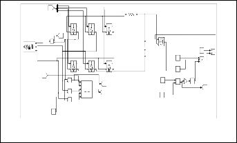
voltage and current waveforms of ASD.
The harmonics generated by a large power converter which covers a wide range of frequencies can cause serious problems of interference to power line carrier (PLC) communication systems and effect many number of equipments in the power system. The pulse width modulation (PWM) technique proved that it is ideal with static three phase inverter used in the UPS system as shown in the simulation model for power converter which is represented in Fig. 11 and Fig.11a shows simulated waveforms of supply voltage and current of Power converter.
Fig.11. simulation model for power converter
[pulses ]
From 1
IG /D1
g m
IG/D3
g m
R IG /D5
g m
C E
[Ia ]
i Goto 3
A -
C E C E
s
+
-
B C
Three -Phase Source
Current Measurement
IG /D2
g m
C E
IG/D4
g m
C E
IG /D6
g m
C E
Controlled Current Source
2.3
Constant
230
14920
Constant 4
Product
Divide
[alpha ] From
+
- alpha_deg
[Vab]
-C-
Constant 1
min
-K-
cos
Voltage Measurement
AB
Goto 2
Constant 2
MinMax Gain Trigonometric
Function
[alpha ]
+
-
Voltage Measurement1
+
-
Voltage Measurement2
BC pulses
CA Block Synchronized
6-Pulse Generator
[pulses ] Goto
1
Goto 1
Constant 3
Fig.11a. Simulated waveforms of supply voltage and current of
Power converter
0
Constant 5
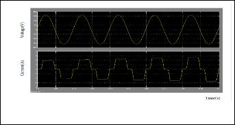
Fig.10. Simulation model for Adjustable speed Drive
Fig.10a. supply voltage and current waveforms of ASD
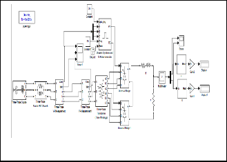
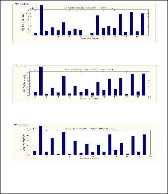
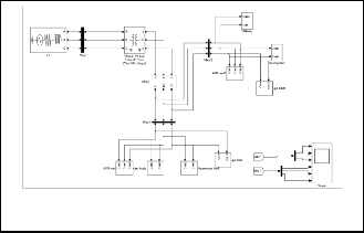
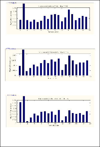
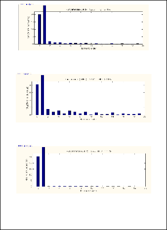
For simulation MATLAB/SIMULINK package has been used to simulate the electrical load distribution system as shown in Fig.12. Fig.12a and 12b indicate FFT analysis of voltage wave- forms without UPQC and with UPQC respectively. Fig.12c and
12d indicate FFT analysis of current waveforms without UPQC and with UPQC respectively. The software package Simulink7.5 is used for modeling, simulating and analyzing the system. It supports linear and nonlinear systems, modeled in continuous time, sampled time or a hybrid of the two.
IJSER © 2012
International Journal of Scientific & Engineering Research Volume 3, Issue 6, June-2012 6
ISSN 2229-5518
Va
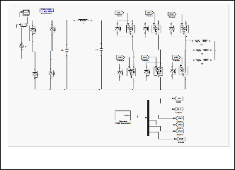
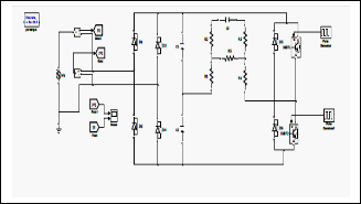
Fig.12. Simulation model of electrical load distribution system with UPQC in Matlab /Simulink
In this model the power supply is obtained from 3-phase, 11kv feeders. Here, 11kV/415V transformer is used to step down the voltage and connect to the loads. In this model loads like Adjust- able Speed Drive, ten Personal Computers, ten fluorescent lamps and Uninterruptable Power supply are connected to the system in different phases and the variations in supply parameters in the three phases are observed. Due to the presence of nonlinear loads, harmonics are introduced into the system.
Vb
Vc
Fig.12b. FFT analysis of voltage waveforms with UPQC
Va
Ia
Vb
Ib
Vc
Fig.12a. FFT analysis of voltage waveforms without UPQC
IJSER © 2012
Ic
Fig.12c. FFT Analysis of current waveforms without UPQC
International Journal of Scientific & Engineering Research Volume 3, Issue 6, June-2012 7
ISSN 2229-5518
Ia
Ib
Ic

Fig.12d. FFT Analysis of current waveforms with UPQC
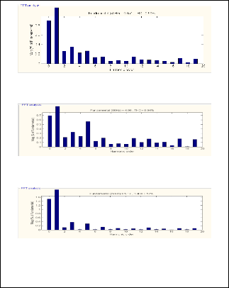
TABLE-1
COMPARISON OF THDI’s & THDV’s FOR ELECTRICAL LOAD
DISTRIBUTION SYSTEM WITH AND WITHOUT UPQC
THDV (%) | THDI (%) | |||||
Va | Vb | Vc | Ia | Ib | Ic | |
Without UPQC | 0.05 | 0.11 | 0.06 | 3.11 | 3.11 | 1.11 |
With UPQC | 0.02 | 0.04 | 0.02 | 0.69 | 0.94 | 0.57 |
As seen form the table-1, the percentage of Total Harmonic Distortion due to voltage (THDV) and Total Harmonic Distor- tion due to current (THDI) with and without Unified Power Quality conditioner (UPQC) are analyzed. The total harmonic distortion levels are reduced to a considerable extent by the use of Unified Power Quality Conditioner.
The Harmonic analysis of the electrical load distribution system is performed to study the behavior of different nonli- near loads. This paper presented the modeling of various non-
linear loads used for both residential and commercial applica- tions through simulation and the total harmonic distortion evaluated. The different single phase nonlinear loads like Per- sonal Computers, Fluorescent lamps, Uninterruptable power supply and three phase nonlinear loads like Adjustable Speed Drive and power converter are modeled. The THD’s with and without using Unified Power Quality Conditioner are com- pared for distributed load containing these non linear loads. The total harmonic distortion due to voltage and total har- monic distortion due to current are reduced by using UPQC. Especially the total harmonic distortion due to current is re- duced effectively. From the above findings UPQC can be used to reduce the harmonic levels.
[1] C. Venkatesh, D. Srikanth Kumar, Student Members, IEEE, D.V.S.S.
Siva Sarma, Senior Member, IEEE and M. Sydulu, Member, IEEE,
“Modeling of Nonlinear loads and Estimation of Harmonics in In- dustrial Distribution System” Fifteenth National Power Systems Confe- rence (NPSC), IIT Bombay, December 2008, pp 592-597
[2] Arrillaga, J. Bradley , D.A., Bodger, P.S., “Power System Harmonics,”
John Wiley and Sons, New York,1985 .
[3] Wang Yifei; Chen, S.; Choi, S.S.; “An Overview of Various Ap- proaches to Power System Harmonic Analysis” International Power Engineering Conference, IPEC 2007, pp.338-343.
[4] Jose Antinor Pomilio, Sigmar Maurer Deckmann,“Characterization and Compensation of Harmonics and Reactive Power of Residential and Commercial Loads,” IEEE Transactions on Power Delivery, vol.2, Issue.2, 2007, pp.1049-1055.
[5] “IEEE Recommendation Practices and Requirements for Harmonics control
in Electrical Power Systems” published by IEEE Inc., April 1993.
[6] Mansoor, A.; Grady, W.M, “Analysis of Compensation Factors In- fluencing the Net Harmonic Current Produced by Single-phase Non- Linear Loads”, 8th International Conference on Harmonics and Quality of Power-1998, vol.2, pp.883-889.
[7] Task Force on harmonics modeling and simulation, IEEE PES Har-
monic Working Group, “Characteristics and modeling of Harmonic Sources-Power Electronics Devices”, IEEE Transactions on Power Deli- very, vol.16, No.4, Oct.2001, pp.791-800.
[8] Task Force on Harmonics Modeling and Simulation, “Modeling De- vices with Nonlinear Voltage-Current Characteristics for Harmonic Studies”, IEEE Transactions on Power Delivery, vol.19, Issue.4, October
2004, pp.1802-1811.
[9] The control techniques drives and control hand book V.Khadkikar, A. Chandra , O.Berry and T.D.Nguyen, 2006, “Conceptual study of Unified Power Quality Conditioner (UPQC)”. IEEE ISIE, pp.207-211.
[10] JenoPaul, Ruban Deva Prakash, Jacob Raglend” Design and Simulation of Phase Locked Loop Controller Based Three Phase Unified Power Quality Conditioner for Nonlinear and Voltage Sensitive loads”, Inter- national journal of applied Engineering research,Dindigul,Vol.1,No.2, 2010.
[11] Bhim Singhy and Venkateswarlu.P, 2010“A Simplified Control Algo-
rithm for Three Phase, FourWire Unified Power Quality Condition-
er”. Journal of Power Electronics, Vol.10, No. 1, pp 912-918.
[12] PengCheng Zhu, Xun Li, Yong Kang and Jian Chen, 2005 “Analysis
and experimental verification of a control scheme for unified power quality conditioner” Int. J. Energy Technology and Policy, Vol. 3, No. 3, pp 253-259.
IJSER © 2012