International Journal of Scientific & Engineering Research Volume 3, Issue 4, April-2012 1
ISSN 2229-5518
Hydraulic Regenerative Braking System
ER. Amitesh Kumar
ABSTRACT- Hydraulic regenerative braking system is an important branch of hybrid technology, which has the advantage of high power density and the ability to accept the high rates/high frequencies of charging and discharging, therefore hydraulic regenerative braking technology is well suited for off-road vehicles and heavy-duty trucks. Relatively lower energy density and complicated coordinating operation between two power sources require a special energy control strategy to maximize the fuel saving potential. This paper presents a new configuration of parallel hydraulic regenerative vehicle (PHRBV) to improve the braking energy regenerated potential and engine work efficiency. Based on the analysis of optimal energy distribution for the proposed PHRBV over a representative urban driving cycle, a fuzzy torque control strategy based on the vehicle load changes is developed to real-time control the energy distribution for the proposed PHRBV. Simulation results demonstrate that the proposed PHRBV with torque control strategy takes advantage of the high power density and efficiency characteristics of the hydraulic regenerative braking system minimizes the disadvantages of low energy density and effectively improves the fuel economy of PHRBV.
Keywords – Fuzzy logic controller System, Fuzzy control principle, Hydraulic system schematic, parallel hydraulic regenerative braking system
—————————— ——————————
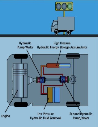
ONE must first understand what a Hydraulic regenerative braking system is, and how it works. The basic idea of a Hydraulic regenerative braking system is that when the vehicle slows down or decelerates, it will store the kinetic energy that was originally momentum as potential energy in the form of pressure. This is done by
using a displacement pump to pump hydraulic fluid into an accumulator. When the vehicle accelerates, the pressure is released from the accumulator which will spin the drive shaft and accelerate the vehicle. Thus the engine remains idle while the pressure is released and when the accumulator is empty, or the desired speed is achieved, the engine will then engage in order to maintain a constant velocity, or to accelerate the vehicle beyond what the capacity of the accumulator was capable of. fig 1.1 shows the basic construction of it.![]()
Er.Amitesh Kumar(Mechanical Engineer) Masters of Engineering in Automotuve Engineering from Sinhgad Academy of Engineering, Pune, India.
E-mail: amitesh.parasar@gmail.com
Figure 1.1: hydraulic regenerative braking system
Inefficient fuel usage is often unavoidable for many vehicles. Most specifically, vehicles that operate under frequent stop and go conditions, such as delivery
IJSER © 2012 http://www.ijser.org
International Journal of Scientific & Engineering Research Volume 3, Issue 4, April-2012 2
ISSN 2229-5518
vehicles, are most affected by these inefficiencies. With increasing fuel prices and inefficient fuel use, there is an obvious need for a more resourceful solution. The solution is Hydraulic regenerative braking system.
The primary objective of this topic is to validate that a Hydraulic regenerative braking system can increase the stop and go fuel efficiency of a vehicle by 32%.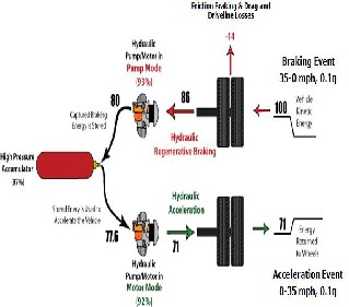
Figure 1.2: Efficiencies while braking/ accelerating
The design is transparent so that the control of this system functions as intuitively as possible. It was designed to be controlled by gas and brake pedals so that any new user will be familiar with its control. The design of the hydraulic system was created so it in no way hinders the performance or integrity of the vehicle. Not only will the system be predictable in use, it will be reliable and consistent.
The scope of the topic was to test hydraulic regenerative braking technology, rather than designing a marketable system. Much of the time was spent on better understanding and implementing the knowledge and
design aspect of the hydraulic regenerative braking system.
Hybrid vehicles are becoming more and more common in the auto industry. A hybrid vehicle is simply a vehicle that operates using a primary engine and secondary energy storage device. While electric hybrid vehicles are the most familiar and have been commercially produced, Hydraulic regenerative braking system technology is being investigated as a better hybrid option. Hydraulic regenerative braking vehicles are being introduced into the industry by companies such as Parker Hannifin Corporation and Eaton Corporation. Hydraulic regenerative braking system can be divided into two different system types: parallel and series.
In a parallel hydraulic hybrid, the hydraulic components are connected to the conventional transmission and driveshaft. While the engine is always running and consuming fuel, the hydraulic system is able to assist in acceleration when the engine is working its hardest, thus increasing fuel efficiency. Series hydraulic hybrid systems use the same basic principles as parallel systems, but do not utilize the conventional transmission or driveshaft. The hydraulic system transmits all power directly to the wheels.
A hydraulic hybrid offers a number of advantages over electric hybrids. The largest of these advantages is that the system employs less energy conversions, leading to higher efficiencies. An electric hybrid converts kinetic energy to electrical energy and then to chemical energy that is stored in a battery. A hydraulic hybrid converts kinetic energy to fluid pressure energy and this is how the energy is stored. This results in one less energy form conversion to help the hydraulic regenerative braking system achieve higher efficiency than other types of hybrids.
IJSER © 2012 http://www.ijser.org
International Journal of Scientific & Engineering Research Volume 3, Issue 4, April-2012 3
ISSN 2229-5518
Hydraulic Regenerative braking is a large advantage to a hybrid system, especially when the vehicle is subject to frequent stops. Normally, in a conventional vehicle, all of the kinetic energy is lost to heat, an irreversible process. A hybrid however captures some of this energy through regenerative braking to be reused the next time the vehicle accelerates. Through simulations, it was estimated that 70% of the kinetic energy of the vehicle would be recycled through a regenerative braking event
with the hydraulic regenerative braking system.
Operating the engine of a hydraulic regenerative braking vehicle at its optimal operating point is of value because the engine can generate the most power per flow rate of fuel. To find this point for the engine used in this project, the following data was obtained from the manufacturer: engine power versus engine speed, engine torque versus engine speed, and engine fuel consumption rate versus engine speed. These data graphs are presented below in Figure 2.1, Figure 2.2, and Figure 2.3. The engine used in this project is represented by the orange line in all three figures. From this, a ratio was calculated at each engine speed of engine power or torque per volumetric flow rate of fuel. This was then graphed to find the optimum operation point. From Figure 2.4 and Figure 2.5, it was determined that the slower the engine runs, the better the torque per fuel consumption rate. However, the power graph shows a speed at which the engine maximized the amount of power obtained per fuel flow rate. From this data, the engine would be tuned to run at about 2200 rpm when pumping hydraulic fluid. This speed is close to the optimal operating speed for our engine, thus providing the best use of the fuel consumed by the engine.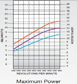
Figure 2.1: Engine power data
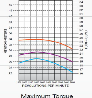
Figure 2.2: Engine torque data
IJSER © 2012 http://www.ijser.org
International Journal of Scientific & Engineering Research Volume 3, Issue 4, April-2012 4
ISSN 2229-5518
Figure 2.3: Engine fuel consumption data
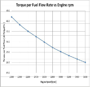
Figure 2.4: Graph of torque per fuel flow rate versus engine
speed
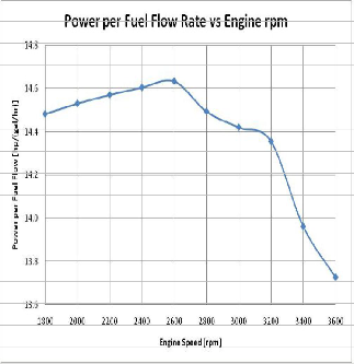
Figure 2.5: Graph of power per fuel flow rate versus engine speed
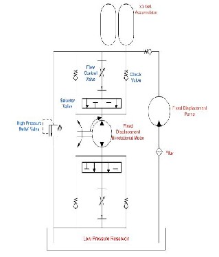
A Hydraulic regenerative braking system schematic was created for a series hydraulic hybrid vehicle. This schematic was designed to include acceleration and braking control using hydraulic flow control valves, regenerative braking using check valves, and forewords and reverse directions using a directional selector valve. An important safety feature of the hydraulic schematic is the high pressure relief valve, which ensures that the pressure in the system never reaches an unsafe level. A copy of this schematic can be found in Figure 2.6
IJSER © 2012 http://www.ijser.org
International Journal of Scientific & Engineering Research Volume 3, Issue 4, April-2012 5
ISSN 2229-5518
meantime, adjust the engine working point onto the optimal fuel consumption region. When the hydraulic accumulator pressure reaches the highest initiative charging pressure value, the vehicle is driven by the hydraulic accumulator and hydraulic pump/motor. The introduction of hydraulic pump minimizes the lower energy density disadvantage of the accumulator and makes the engine work in high efficiency region through the initiative charging function.
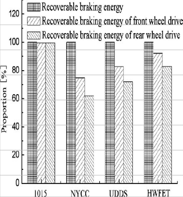
Allocate the hydraulic pump/motor behind the front differential (the front-wheel-drive model) has a greater potential in braking energy regeneration because of the increasing of the front axle load during braking. The front wheel braking force Ff1 and the rear wheel braking force Ff2 are given by [Eq. (1) and (2)], respectively.
Fig. 2.6 New configuration of parallel hydraulic regenerative braking system.
Fig.2.6 presents a new type of configuration for hydraulic regenerative braking system which consists primarily of an engine, a high-pressure accumulator, a low pressure reservoir, a variable displacement hydraulic pump, and a variable displacement hydraulic pump/motor unit, clutch, transmission and differential. The hydraulic pump/motor and hydraulic pump are coupled to the propeller shaft via a planetary gear system. During deceleration, the hydraulic pump/motor decelerates the vehicle while operating as a pump to capture the energy normally lost to friction brakes in a conventional vehicle. Also, when the vehicle brake is applied, the hydraulic pump/motor uses the braking energy to charge the hydraulic fluid from a low pressure hydraulic accumulator into a high-pressure accumulator, increasing the pressure of the nitrogen gas in the high-pressure accumulator. The high pressure hydraulic fluid is used by the hydraulic pump/motor unit to generate torque during the next vehicle acceleration. It is designed and sized to capture braking energy from normal, moderate braking events and is supplemented by friction brakes for aggressive braking. Cruise conditions, the hydraulic pump works for charging the hydraulic accumulator,
where u is the friction coefficient between tire and road
surface, a is the distance from vehicle center of gravity to front axle center line, b is the distance from vehicle center of gravity to rear axle center line, L is the wheel base and hg is the height of the center of gravity. During the
course of braking, the front axle load increases and the
rear axle load decreases, therefore, install pump/motor
behind the front differential has greater potential in
braking energy regeneration. The regenerative braking
torque distributions under different pump/motor install
position are shown in Figs. 3.1 and 3.2 the impact of
hydraulic pump/motor install position on braking
energy regeneration under different driving cycles is
shown in Fig.3.3
Parallel hydraulic hybrid vehicle mainly includes the hydraulic driving condition, cruise condition, accelerating/climbing condition and regenerative braking condition.
IJSER © 2012 http://www.ijser.org
International Journal of Scientific & Engineering Research Volume 3, Issue 4, April-2012 6
ISSN 2229-5518
When vehicle starts and the pressure of hydraulic accumulator is higher than the minimum working pressure value, the commanded power of vehicle is supplied only by hydraulic pump/motor. When the pressure in hydraulic accumulator declines to the minimum working pressure value, the vehicle is switched to cruise condition.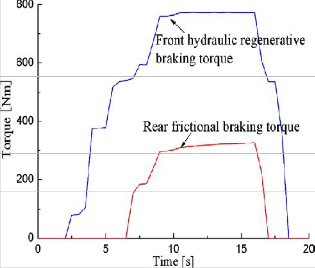
Fig. 3.1. Regenerative braking torque distribution of front-wheel- drive model.
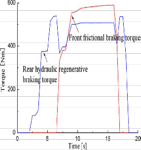
Fig. 3.2 Regenerative braking torque distribution of rear wheel drive.
Fig. 3.3 Impact of hydraulic pump/motor configuration on braking energy regeneration.
During the course of low-speed cruise condition, major output power of the engine is used for driving vehicle, the others power is used for charging the hydraulic accumulator, meantime, adjusts the engine load. The torque relationship is shown as [Eq. (3)]![]()
where Td, Teng and TP are the torque of differential, the engine output torque and hydraulic pump charging
torque, respectively, ig is the velocity ratio of transmission, iP is the velocity ratio of hydraulic pump to the propeller shaft, np is the efficiency of hydraulic pump to the propeller shaft, ne, nt are the efficiency of engine and the efficiency of transmission and Td, l is the
torque loss due to friction and churning loss for the
transmissions to differential.
IJSER © 2012 http://www.ijser.org
International Journal of Scientific & Engineering Research Volume 3, Issue 4, April-2012 7
ISSN 2229-5518
During the course of middle-speed and high-speed cruise course, in order to enable the engine work at a relatively middle speed region, the hydraulic pump/motor supply auxiliary power, the hydraulic pump offers hydraulic oil for the pump/motor or charging hydraulic accumulator. The torque relationship is shown as [Eq. (4)]![]()
Td, l
Where TP/M is the torque of hydraulic pump/motor,
iP/M is the velocity ratio of hydraulic pump/motor to
the propeller shaft and nP/M is the efficiency of
hydraulic pump/motor to the propeller shaft.
In order to enable the engine runs in a certain region or a smooth rise, the hydraulic pump does not work and the hydraulic pump/motor provides
is shown as follows: the auxiliary power. The torque relationship. [Eq.(5)]![]()
During braking, the hydraulic pump/motor works at pump condition, uses the braking energy to charge the hydraulic fluid from a low pressure hydraulic accumulator into a high-pressure accumulator, increasing the pressure of the nitrogen gas in the high-pressure accumulator. The regenerative braking force of hydraulic pump/motor is as follows: [Eq.(6)]![]()
where io is the final ratio of differential. It is designed and sized to capture braking energy from normal,
moderate braking events and is supplemented by friction brakes and engine anti-trailer brakes for aggressive braking. The anti-trailer braking force of engine is determined by [Eq. (7)]![]()
where /e is the engine moment of inertia and z is the severity of braking.
Dynamic programming is a powerful tool to solve general dynamic optimization problems. In this study, the objective is to search for the optimal trajectories of control signals, including the engine command, hydraulic pump command and hydraulic pump/motor command to minimize the fuel consumption of the PHRBV over the whole driving cycle. i.e.[Eq.(8)]![]()
where L is the fuel consumption over a time segment, N is the driving cycle length and x, u are the vectors of state variables and control signals respectively.
(1) The engine fuel consumption. This term only represents the fuel consumption assuming the engine is rotating in a steady state. [Eq.(9)]![]()
(2) The second term is used to compensate the extra fuel consumption for the frequent start/stop engine and shifting gears. [Eq.(10) and (11)]
Frequent start/stop engine and shifting gears worsen fuel consumption and affect the ride comfortableness.
(3) In order to match the final value of accumulator SOC![]()
with its initial value, a penalty term is added. [Eq.(12)]
Where α α, β, γ are the weight coefficients.
Fig.4.1 presents the optimal trajectories of operating
points of the engine and the vehicle operating modes
over the NYCC duty cycle.
The accumulator pressure is characterized by large fluctuations due to high power flows through the system.
IJSER © 2012 http://www.ijser.org
International Journal of Scientific & Engineering Research Volume 3, Issue 4, April-2012 8
ISSN 2229-5518
Large negative swings hydraulic pump/motor power indicate the effective capturing of braking energy. Since the Dynamic Programming algorithm is forward-looking, the resulting optimal control signals are not applicable in practice. By analyzing the DP results, the useful hints for deriving improved strategies can be practically implemented.
Clearly, at the beginning of each vehicle launch, the hydraulic pump/motor provides total propulsion power to avoid forcing the engine to work in the low speed/load region. With the exception of launch, the engine and pump/motor is used exclusively, because engine and hydraulic pump/motor have the characteristics of higher efficiencies at higher loads. Whenever the required power exceeds the maximum power provided by the pump/motor, the engine exclusive working mode is switched. In the meantime, the hydraulic pump is used to adjust engine working load through initiative charging pressure function and keep propulsion component at high load/high efficiency region. During the cruise speed stage, the pump/ motor is used to satisfy the total power demand whenever there is energy available in the accumulator, in the meantime, the frequent dynamical transitions between the various operation modes is needed to avoid.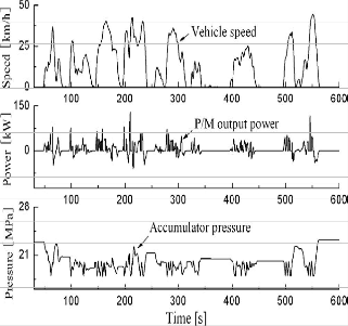
Fig. 4.1 Dynamic Programming results obtained over NYCC driving cycle.
Fuzzy torque control strategy uses fuzzy logic to build an energy distribution controller based on the useful hints derived from optimization results. The vehicle load of PHRBV varies in a wide range, if ignoring the change of vehicle load, the energy control strategy cannot realize
the fuel economy potential fullest. In the paper, the vehicle load is introduced as an input of the fuzzy logic controller through a sense proportion valve to determine the load condition of the vehicle. Appropriately reduce the pump charging torque and maximum charging pressure value when the load is small. Otherwise, enlarge the pump charging torque and maximum charging pressure value.
The three inputs of the fuzzy logic controller are the difference between the optimal torque (corresponding to the current engine rotation speed) and the vehicle required torque, the pressure (SOC) of the accumulator and the vehicle load. The difference between optimal torque and requirement torque (DT) is divided into five fuzzy subsets: {PL, PS, ZERO, NS, NL}. Similarly, the accumulator’s SOC is divided into three fuzzy subsets:
{HIGH, MED, LOW}, and the vehicle load is divided into three fuzzy subsets: {HIGH, MED, LOW}. The two outputs of the fuzzy logic controller are hydraulic pump/motor’s output torque and the hydraulic ump’s initiative charging pressure torque, while the fuzzy subsets are {LARGE, MED, SMALL, ZERO} and {LARGE, SMALL, ZERO}, respectively. Figs.5.1 and 5.2 present the input membership functions and the fuzzy logic block diagram.
Table 1 presents a list of if – then rules that represent the torque control strategy based on the analysis of DP optimization results.
Fig. 5.1 Simplified block diagram of the fuzzy logic controller.
IJSER © 2012 http://www.ijser.org
International Journal of Scientific & Engineering Research Volume 3, Issue 4, April-2012 9
ISSN 2229-5518
= Z, TP = L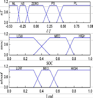
![]()
![]()
The main principle of the fuzzy torque control rules are as follows: (1) DT is equal to zero, which shows that the engine is located in the highest efficiency region and working point need not to be adjusted; (2) DT is PL, which shows that the engine’s efficiency is very low and it should be shut off to make the accumulator providing drive torque alone; (3) DT is PS, which shows that the engine is located in low efficiency region and initiative charging pressure function of hydraulic pump is used to adjust working point into the optimal region; (4) when DT is NL, it should meet the requirement of driving torque instead of economy; (5) when DT is NS, accumulator will help to reduce load.
Fig. 5.2 Input membership functions for the scaled DT, SOC and Load.
TABLE 1
FUZZY CONTROL PRINCIPLE OF
TORQUE CONTROL STRATEGY
![]()
![]()
Conditions Conclusions
In order to check the validity of the fuzzy torque control strategy based on PHRBV, the PHRBV simulation model is implemented in SIMULINK. The simulation parameters of main components are listed in Table 2 and the vehicle configuration is shown in Fig. l.
Traditional power-split strategy, optimal power management strategy and fuzzy torque control strategy are used to compare the improvement of fuel economy. The simulation results are shown in Figs. 6.1–6.3
TABLE 2
PARAMETERS OF THE VEHICLE AND
MAIN COMPONENT
![]()
If DT=NL & P = L Then TP/M ![]()
= L, TP = Z
If DT=NS & P = H Then TP/M
= L, TP = Z
If DT=NS & P =M Then TP/M
= S, TP = Z
If DT = Z Then TP/M
= Z, TP = Z
If DT = PL & P ffi L Then TP/M
= L, TP = Z
If DT = PS & P = H Then TP/M
= L, TP = Z
If DT = PS & P = M & load = L Then TP/M
= Z, TP = S
If DT = PS & P = M & load =M Then TP/M
= Z, TP = S
If DT = PS & P = M & load = H Then TP/M
= Z, TP = L
If DT = PS & P = L Then TP/M
Wheel diameter 0.5 m
Rolling resistance 0.02
Aerodynamic coefficient 0.65
Frontal area 6.5 m2
Total vehicle mass 14,310 kg
Volume 63 L
Max working pressure 32 MPa
Min working pressure 18MPa
Gear ratio 6.62, 3.99, 2.47, 1.55, 1
Main gear ratio 4.85
IJSER © 2012 http://www.ijser.org
International Journal of Scientific & Engineering Research Volume 3, Issue 4, April-2012 10
ISSN 2229-5518
Type and displacement A4VG125
Max torque 795 nm
Displacement 60![]()
![]()
_
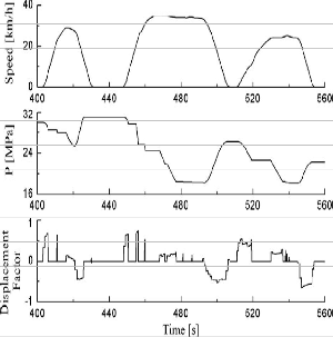
Fig. 6.1 Simulation results of power-split strategy
Fig. 6.2 Simulation results of optimal power management strategy.
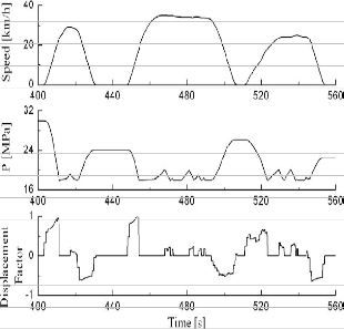
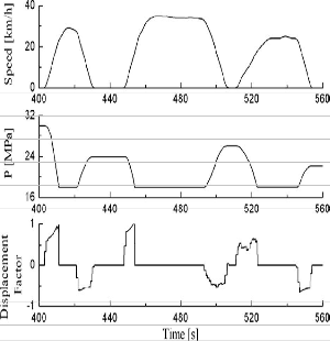
Fig. 6.3 Simulation results of fuzzy torque control strategy.
Figs. 6.1–6.3 show the differences between the power- split strategy, optimal power management strategy and fuzzy torque management strategy. Hybridization significantly improves vehicle’s fuel economy over the city driving schedule. Hydraulic hybrid technology has unique characteristics of high power density compared to their electric counterparts, which enables regenerating and reusing significant amounts of braking energy. The large fluctuations of accumulator pressure demonstrated the effective regeneration and reuse of braking energy. Even using engine universal performance characteristics map to design control strategies (power-split strategy), the fuel economy improved 15.6% compared to the conventional vehicle. However, power-split strategy designed the energy distribution strategy only based on the static engine universal performance characteristics map and ignored the hydraulic hybrid propulsion system characteristics. Consequently, the energy distribution between primary and assistance sources is unreasonable. The regenerative braking ended earlier because the accumulator is fully charged. In addition, the frequent switching between engine mode and pump/motor mode worsens fuel consumption and ride comfortableness.
Optimal power management strategy proposed by used pump/motor to satisfy the total power demand, whenever there is energy available in the accumulator. If the power requirement is more than what pump/motor can provide, the engine will supplement the motor power. But the power management strategy ignored the relatively lower efficiency of engine when the propulsion
IJSER © 2012 http://www.ijser.org
International Journal of Scientific & Engineering Research Volume 3, Issue 4, April-2012 11
ISSN 2229-5518
is switched to engine work mode at the high speed of the vehicle, so that the fuel economy potential can’t be realized to its fullest.
Fuzzy logic controller is used to reasonably distribute the propulsion torque among the engine, hydraulic pump and hydraulic pump/motor. Hydraulic pump/motor is used to satisfy the total power demand, whenever there is energy available in the accumulator. The hydraulic pump is introduced to minimize the lower energy density disadvantages of hydraulic accumulator and move the engine working points into the highest efficiency region through initiative charging function. Hence, they enable a very dramatic increase of PHRBVs ability to realize its fuel saving potential. Implementation of fuzzy torque control strategy improved fuel economy to 32%.
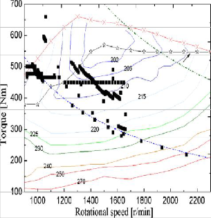
Operating points of the engine controlled by power-split strategy were clustered in the mid/low load region (Fig.6.4). The fuzzy torque control strategy is able to move most points into the mid/high load zone characterized by highest efficiencies (Fig.6.5). In addition, frequent use of the motor for vehicle acceleration often depletes the energy in the accumulator, which prepares the system for the next regeneration event.
The impacts of load changing on the PHHV fuel economy are compared in Fig.6.6 Under 1015, ECE + EUDC, UDDS and HWFET driving cycles, the parallel hydraulic hybrid vehicle with considering the changes of load has higher fuel economy, which demonstrated the effectively of the fuzzy torque control strategy.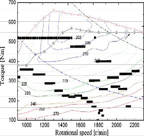
Fig. 6.4 Operating points of engine under power-split strategy.
Fig.6.5 Operating points of engine under fuzzy torque control strategy.
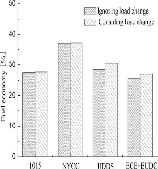
Fig. 6.6 Impacts of load changing on PHHV fuel economy
IJSER © 2012 http://www.ijser.org
International Journal of Scientific & Engineering Research Volume 3, Issue 4, April-2012 12
ISSN 2229-5518
minimized the disadvantage of accumulator’s lower energy density, which provided a practical feasible method for improving fuel economy of the hydraulic hybrid vehicle.
Fig. 6.7 Hydraulic system schematic
A simplified hydraulic system schematic is shown in Figure 6.7 for the three major driving scenarios: accelerating, braking, and coasting. The diagrams trace the fluids route through the system during each of the scenarios.
Hydraulic hybrid technology has the advantage of high power density and the ability to accept the high rates/high frequencies of charging and discharging, therefore it is well suited for off-road vehicles and heavy- duty trucks. But the lower energy density requires a special energy control strategy for PHRBV. In this study, a new type of configuration for PHRBV is presented. A fuzzy-based torque control strategy is built using the optimization results according to the torque distribution among the engine, hydraulic pump/motor and hydraulic pump, and the vehicle load changes is introduced to the fuzzy torque control strategy for realizing the fuel economy fullest. The simulation results show that the new configuration of PHRBV effectively improved the braking regenerative potential. The fuzzy torque control strategy reasonably distributed the propulsion energy between the power sources, improved the fuel economy and adaptability of different working conditions, and
[1] Wei YJ. Study on a new type of hydraulic hybrid sport utility vehicle.Chaina Mech Engg 2006;17(15):1645-8(in Chinese)
[2] Peng D,Yin CL,Zhang JW.Advanced braking control system for hybrid electric vehicle using fuzzy control logic.SAE paper No.2006-01-3583
[3] Paul M, jacek S. Development and simulation of a hydraulic hybrid
powertain for use in commercial heavy vehicle. SAE Paper No.2003-01-
3370.
[4] Hewko LO, Weber TR. Hydraulic energy storage based hybrid propulsion system for a terrestrial vehicle .Energy Convers Engg Conf
1990:99-105
[5] Wu P,Luo N, Fronczak FJ, Beachle NH. Fuel economy and operating characteristics of a hydropneumatic energy storage auto-mobile.SAE paper851678
[6] Wu B, Lin CC,Filipi Z, Peng H, Assanis D. Optimal power management for a hydraulic hybrid delivery truck. Vehicle syst Dyn
2004:23-40.
[7] Lin CC,Peng P, jessy W. power management strategy for a parallel hybrid electric truck. IEEE Trans control Syst Technol 2003(6):839-49.
[8] Kim YJ,Filipi Z. Series hybrid propulsion for a light truck- optimization the thermostatic power management. SAE peper No.2007-24-
0080.
[9] Robyn AJ, Paul S, Steven B. Physical system model of a hybrid energy storage device for hybrid powertrain applications.SAE paper No.
2005-01- 0810
[10] Hiroki S,Shigeru I, Eitaro K. Study on hybrid vehicle using constant pressure hydraulic system with flywheel for energy storage. SAE paper No. 2004-01-3064.
IJSER © 2012 http://www.ijser.org