International Journal of Scientific & Engineering Research Volume 2, Issue 12, December-2011 1
ISSN 2229-5518
GUI/Simulink Based Interactive Interface for a
DC Motor with PI Controller
Bishwajit Dash and Vibindeepak Vasudevan
Abstract— This paper presents an interactive module for understanding the effect of PI (Proportional Integral) controllers in the regulation of DC motor systems. This module uses Simulink model to represent the DC motor model and was given an interactive interface with the Matlab graphical user interface (Matlab-GUI) tool, which makes it easier to learn the control engineering behind PI controls. The paper will go through the development of the GUI interface from the Simulink module, as students and engineers can go through each step involved in it for an interactive learning. The GUI interface created includes the variation of armature current, speed and voltage with respect to variation in DC motor parameters and relay parameters, in conjunction with PI controller.
Index Terms— Control Engineering, DC Motor, Interface, Matlab/ GUI, Proportional Integral Derivative (PID), Simulink, Speed Control, Armature Current Control.
1 INTRODUCTION
—————————— ——————————
he DC motor has been very popular machine in the industry control area for decades now, because they have many useful characteristics, such as high starting torque and response performance and easier to linear control. DC motor has good speed control respondence, wide speed control range and it is used in high control
speed control systems.
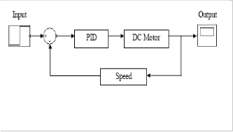
As Fig.1 shows, this is a basic feedback control of a DC motor with PID controller. PID controllers are known to be the finest controllers in industries (even after the advent of fuzzy logic and neural network controllers), because of their robust performance and simple structure. However in our module, we would be using a two term controller, PI (Proportional Integral) controller. PI controllers are used. According to [1], a derivative term controller can sometimes lead to spikes and discontinuities in the output signal, when differentiated.
Fig. 1. Speed Control Feedback Loop of a DC Motor
————————————————
Bishwajit Dash is with the Electrical and Electronics Engineering Department, National Institute of Technology Karnataka, Surathkal, Srinivasnagar (PO), Mangalore-575025, (phone: 09008522483; e-mail: bdashh@gmail.com).
Vibindeepak Vasudevan is with the Electrical and Electronics
Engineering Department, National Institute of Technology Karnataka, Surathkal, Srinivasnagar (PO), Mangalore-575025, (phone:
09972331987; e-mail: vbndpk@gmail.com).
This paper would discuss the step by step approach in creating a GUI module in Matlab GUIDE from a Simulink Model of a DC Motor with PI Controllers. This step by step approach is undertaken to ensure proper understanding of the process of creating GUIs to represent electrical machinery and how the various parameters can be differed in real time to see the changes in the machine‟s output characteristics. The paper discusses the M-file coding behind the GUI and the interfacing of the DC Motor Simulink model to GUI.
2 GRAPHICAL USER INTERFACE/ GUIDE
GUI creates graphical display in one or more windows containing controls, called components that enable a user to perform interactive tasks. The user of the GUI does not have to create a script or type commands at the command line to accomplish the tasks. Unlike coding programs to accomplish tasks, the user of a GUI need not understand the details of how the tasks are performed. The graphical user interface (GUI) can make the understanding of the effects of PI controller and various other parameters on the DC motor functionality, become more interactive, interesting and user friendly.
The interactive module is created on the foundation of a Simulink model, which is given a user friendly environment with GUI. The main advantage of Matlab GUIDE (GUI Design Environment) over Visual Basic or COBAL is the combination between graphical visual programming and code programming more straightforwardly. GUIDE GUIs define most of the properties within the figure itself. They store the definitions in its FIG-file rather than in its M-file. You, as a creator of GUI, can use the callbacks to handle each parameter in the GUI. MATLAB software also provides functions that simplify the creation of standard dialog boxes, for example to issue warnings or to open and save files.
IJSER © 2011
http://www.ijser.org
International Journal of Scientific & Engineering Research Volume 2, Issue12, December-2011 2
ISSN 2229-5518
3SIMULINK MODEL
3.1 Background of DC Motor
Before we create a GUI interface, we need to start off with a Simulink model of the DC motor system with PI controller. The DC motor has to be modeled first, in Simulink and the mathematical equations behind the
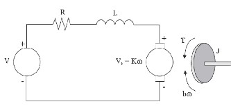
Fig. 2. DC Motor Functioning Diagram
functioning of the motor has to be understood before advancing further.
In order to model a DC Motor in Simulink, we have to define the mathematical equations on which it functions, based on the parameters given in Table I. The DC Motor functioning diagram is given in Fig.2. According to the above diagram, the governing equations are (based on Newton‟s Law and Kirchhoff‟s Law):
the GUI, we did not use the DC Motor model or the PI Controller we created above. We used subsystems available in Simulink Library to simulate the DC Motor and Speed Controller as it was easier to link with the GUI Modeling, as we need to change the in-built parameters of the blocks.

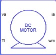
Fig. 2. DC Motor Subsystem and the model behind the mask
The Simulink model was created by using the blocks in the
Simulink library
as well as subsystems we created. Subsystems can be
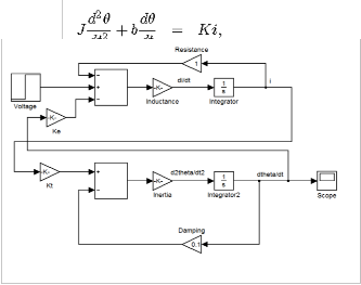
TABLE I

DC MOTOR AND PI CONTROLLER PARAMETERS

Symbo l
Quantity Unit / assumed value at start
J Moment of inertia of rotor
b Damping friction of
motor
1.5 x 10⁻⁴ Kg.m2
1 x 10⁻³
R Electric resistance 2 Ω
L(H) Electric inductance 0.0052 H
K Electromagnetic coupling coefficient
0.1 N.m/A
Fig. 3. A Starting Model of DC Motor in Simulink
Figure 3 represents a simplistic approach in Simulink to create a DC Motor and to analyze its output. Taking [3] as a reference, a PID controller was modeled before hand in Simulink to understand the governing equations and functionality behind the working.
3.2 Creation of Simulink
For the Simulink model we created for interfacing with
Kp Proportional Gain 5
Ki Integral Gain 0 pu Saturation limit 18
RELAY PARAMETERS
Switch on point 2
Switch off point -2
created by using in ports and out ports for each variable. Then, the system can be given a mask of subsystem, as shown in Fig.4 for a DC motor.
The Speed controller or the PI controller also has a similar subsystem mask. The various variables used in the
IJSER © 2011
http://www.ijser.org
International Journal of Scientific & Engineering Research Volume 2, Issue12, December-2011 3
ISSN 2229-5518
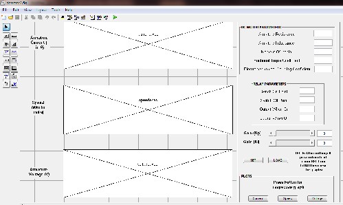
Fig. 4. GUI Layout creation – Matlab GUIDE
shown below, in Fig.5. The parameters of DC motor as well
creation of the Simulink model are listed below in the
Table I, along with the starting value for each of the parameter.
The Simulink model should be fully analyzed and the time configuration of the model was set for analyzing of the output variables in the scope. The Simulink model can be checked by simulating the model and checking the outputs in the scope. Our results were verified with [7], before interfacing the Simulink model to GUI.
4 GUI INTERFACE OF DC MOTOR WITH PI CONTROLLER
4.1 Creation of interface
GUIDE, the graphical user interface environment for Matlab was used in the creation of the interactive module. The tools provided simplify the process of creating GUI layout, as the user has to just drag and click the required GUI components such as sliders, axes, panels and so on- into the layout region of the GUI module. The main advantage of GUIDE is the fact that it automatically generates the M-file code for the GUI layout as well as each of the components in it. In order to make any changes in the components, one can make it in the .fig file itself for each GUI components. Only the interfacing of the working codes or Simulink model has to be done in the GUI Programming.
The module created for the execution of our objectives is
as relay parameters are given a type box to enter the values; while the Kp and Ki values are entered through setting the sliders. This was done to give more flexibility to module, as the effect of the values of PI controller gains on the DC motor is our main objective.
4.2 Description of the tool
Its interface allows the user to change every parameter of the DC Motor as well as the PI Controller gains. In the first group of controls, users can select the parameters of the DC
motor drive and the second group for the values of the
Relay parameters.
The difference between the first two groups and the third group, which deals with the control (tuning of the PI controllers), is that the later uses slider for change of the gain values. This allows the user to visualize and changing the values much faster and facile. Users can also customize the model by setting all model parameters in the Simulink model, beforehand as the GUI also does the same thing in an interactive way.
The SET and LOAD buttons in the interface was provided in order to facilitate the storing of the current, voltage and speed values for each change, before it is plotted. The data for each is stored in.mat files (the code for this is shown in Table II on last page).
Finally, we can visualize the results of speed, armature current, and armature voltage, with respect to any change in the DC motor parameters. The Simulink, in Fig.3 is used
IJSER © 2011
http://www.ijser.org
International Journal of Scientific & Engineering Research Volume 2, Issuel2, December-2011 4
ISSN 2229-5518
to interface with the CUI by certain Matlab codes shown in
Table IL The codes shown below are some of the sample
codes we have used in our CUI programming. Our
Simulink system name was 'simfri'.
-Jl dcmotor2 -------Oc 9
IPARAMETERS
MOTOR PARAMETERS---------,
Armature Resist ance
Armature Current O inA)
Speed (Wm in radls)
-2
-4
0
100
50
-50
0.06 0 07
ooj
Armature Inductance
Moment Of Inertia Frictional Toque Coefficient Electromechanical Coupling Coefficient
RELAY PARAMfTERS
Switch On Point
Switch Off Point -3
Output When On 6()
Output When Off .6()
0.005
0.00Dt 8
0.002
0.3
I
Armature
-100
100
50
Gain (Kp)
8
Gain (K ij
•II
NOTE:After setting .., parlllleters r..-st
press SET then
LOAD then wiew
the gnphs
Voltage M
-50
PLOTS
Press button for
respedive graph
-100
0
0.01 0.02 O.D3 0.04
time in s
0.05 0.06 0.07
0.08
1Jldcmotor2
PARAMETERS
DC MOTOR PARAMETERS - --------;
Armature Current (I inA)
Armature Re sist ance
Armature Inductance
10
0.0004
Moment Of Inertia 0.002
Frictional Toque Coefftcient 0.001
Electromechanical Coupling Coefficient 0.1
:RE:E:::
50
Speed (Wm in rad/s)
-50
SW1tch Off Point Output When On Outout When Off
-3
6()
.6()
Gain (Kp) Gain (Ki)
·r=r==-
•[ I •I 100
Armature
Voltage M
time in s
PLOTS
I_ I Ca-re« J
NOTE:After setting •II p•remeters fir.t press SET then LOAD then view
the graphs
Press button for
respective graph
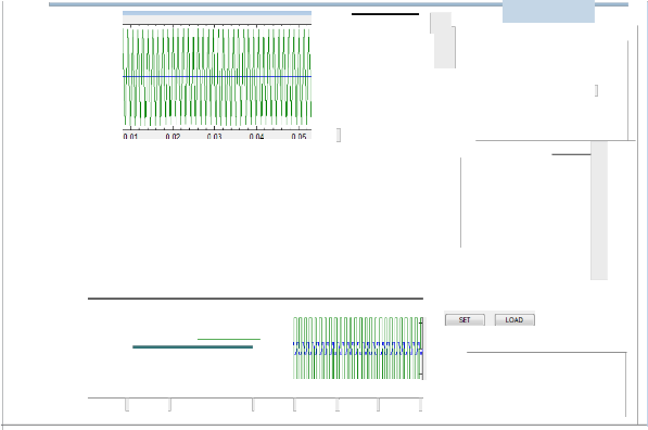
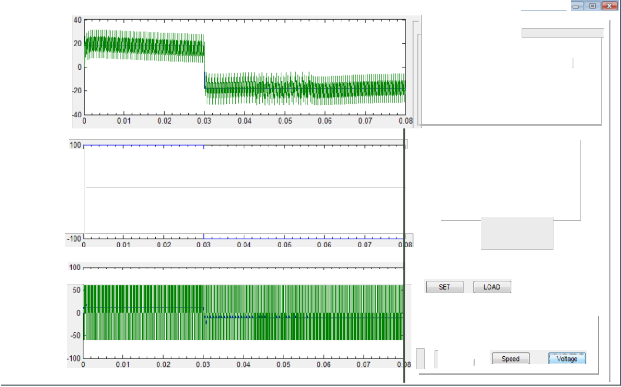
Fig.S Working of GUI for various parameter changes
http://www.tJ ser. org
International Journal of Scientific & Engineering Research Volume 2, Issue12, December-2011 5
ISSN 2229-5518
5 RESULTS
The results obtained from the GUI module are shown below. It reflects the module‟s capabilities to be user friendly, fast and interactive. The following screenshots are taken by varying the parameters to study the output characteristic change in the GUI module. The GUI module and the outputs are shown in Fig.5. As can be seen from the Fig.5, that as we vary the parameters within the GUI the results are being affected, which leads us to say that the parameters of the SIMULINK models are successfully being altered to the desired results from the GUI.
6 CONCLUSION
The purpose of this project was to create an interactive GUI to control the parameters of a SIMULINK model of a DC motor and display the results in the GUI itself. The results could have been displayed in a table format with values taken from the model, but graphs were chosen as the means to display results as they portray the changes in the parameters to the user more effectively. Also a visual aid is more appealing and out aim was to make it interactive. A lot more information can be drawn from the graphs by analyzing the slopes, the dips and rises. However, our purpose was not to analyze the data generated but to simply create an interface between the user and the model, giving the user enough capability for changing the
REFERENCES
[1] M.Nizam Kamarudin and Sahazati Md.Rozali, “Simulink Implementation of Digital Cascade Control DC motor Model- A didactic approach” 2nd IEEE International Conference on Power and Energy, Dec 1-3, 2008, Johor Baharu, Malaysia
[2] Nourdine Aliane, “A Matlab/Simulink- Based Interactive Module
for servo Systems Learning” IEEE Transactions on Education, Vol
53, No.2, May 2010
[3] Nurul Izzati Binti Pandak Jabo, “Speed Control of DC Motor using PID Controller Implementation with Visual Basic”
Universiti Malaysia Pahang, November 2008
[4] B. C. Kuo, Automatic Control Systems, 5th ed. Englewood Cliffs:
Prentice-Hall, 1987.
[5] K.Ogata, Modern Control Engineering. Englewood Cliffs: Prentice- Hall, 1996.
[6] Patrick Marchand and o. Thomas Holland, Graphics and GUIs with
MATLAB, 3rd ed., CRC Press, US
[7] Wai Phyo Aung, “Analysis on Modeling and Simulink of DC motor and
its Driving System Used for Wheeled Mobile Robot” World Academy
of Science, Engineering and Technology 32 2007, MTU, Myanmar
[8] MathWorks, 2009, What is SIMULINK, the MathWorks, Inc. [9] MathWorks, 2009, What is GUIDE, the MathWorks, Inc.
TABLE II
MATLAB CODES FOR INTERFACING SIMULINK AND GUIDE

Code Function
parameters of the model, to how they desired and generate
graphs for them to see and analyze. So the GUI developed can be used as a learning tool for DC motor in the
open_system('simfri') Opens the specified system
classroom. It would keep the students engaged if a hands on session takes place allowing them to acquire information and hence knowledge more effectively and quickly.
The GUI can be extended to other purposes also and not only learning about the DC motor. It can be used for learning induction motors, alternators, image processing
open_system('DCMOTOR',
'parameter')
set_param('simfri/DCMO TOR','Ra',R)
Opens the parameter box of specified block
Changes the Ra parameter to the value the user assigned in Simulink block
and other. The use of a GUI through MATLAB is quite
extensive as it can be coupled with other toolboxes in MATLAB quite effectively making it an appealing prospective for students to learn about a new topic or area of interest.
ACKNOWLEDGMENT
This work was done as a part of curriculum requirement of the Department of Electrical and Electronics Engineering, National Institute of Technology Karnataka, India. Special thanks to our mentor and guide, Dr. Debashisha Jena, Dept. of Electrical and Electronics Engineering, NITK for his valuable advice and help throughout the course of our project and his lectures on Control Theory, which instilled the interest within us.
load current.mat Load the data for the current
values at each time interval
IJSER © 2011
http://www.ijser.org