
Figure: 1
International Journal of Scientific & Engineering Research, Volume 5, Issue 7, July-2014 153
ISSN 2229-5518
GSM Networks: Substantiation of GSM Stationed algorithm
Abstract:
Global System for Mobile Communications also referred to as GSM, is a standard developed by the ETSI (European Telecommunications Standards Institute) which consist of protocols defined for 2G networks used for mobile phones. W ireless as per the frequency of operation and access legality, various applications are distributed. GSM is a second- generation digital mobile cellular communication standard with international roaming initiated by ETSI. It uses two 25GHz frequency bands (890GHz- 915GHz for reverse link and 935GHz- 960GHz for forward link). It uses FDD (frequency division duplexing) and combination of TDMA and FDMA for access between users. The three major subsystems specified in architecture of GSM are:
a) MS- mobile station
b) BSS- base station subsystem
c) NSS- network station subsystem.
Mobile station is the technical term used for mobile cell phone used by users.
MS consist of handset and SIM (Subscriber Identity Module). 32 kilobytes or 64 Kilobytes SIM card in MS has inherent security features for securing the transactions over the wireless medium by encryption and using IMSI (International mobile Subscriber Identity) number. SIM uses A5 and A8 algorithm for security purpose using a key stored in the SIM.
The wireless link interface uses between MS and BSS is technically termed as Um interface. BSS divides into two subcomponents, base transceiver station (BTS) and Base Station Controller (BSC). More than one BTS’s are controlled by one BSC. The interface between them is called as Abis interface. BSS is used to translate protocols between wireless and wired medium.
BSC’s connect to MSC’s (Mobile Switching Center), a part of NSS which acts as a major controller of many BSC’s. An interface is used between BSC’s and MSC. NSS function is to control the network operations and it also acts as a link between PSTN and cellular networks. It uses authentication and authorization algorithms such as A3 key generation for security purposes.
In this paper we will provide details of the algorithm A5/1, A5/2, A5/3, A5/4, A3, and A8 and call flow. This algorithm is used for encryption by the network providers for encrypting the wireless communication. We have defined here how the algorithm works, how it is implemented and its detailed encryption block diagram. We have performed the thorough analysis of algorithm which is shown in this paper.
Keywords:
GSM, A5/1, A5/2, A5/3, A5/4, A3, A8, MSC, BSS, BSC, BTS, MS.
Objective:
In this paper we will explain the concepts of GSM security and working of the actual call, the steps and signals involved in it, which algorithm are required and how they provide security to the wireless communications. W e have also described the working of GSM networks in detail. The algorithms
we have described are A5/1, A5/2, A5/3, A5/4, A3 and A8. All the versions of A5 algorithm are considered here for better understanding.
—————————— ——————————
The figure 1 shows the detailed version of signaling in the call initialization phase. The sequence diagram here explains the sequencing of signals.
Some abbreviations:
RIL: - Radio Interface Layer. RR: Radio Resource.
————————————————
• Romil Gandhi is currently pursuing master’s degree program in Computer
Engineering in Shree L.R Tiwari College of Engineering, India, PH-+91
9819545411 . E-mail: romil.gandhi@gmail.com
• Amitha Nair is currently pursuing master’s degree program in electronics engineering in Shree L.R Tiwari College of Engineering, India, PH-+91
9819915875. E-mail: nair.amitha@gmail.com
DTAP: - Direct Transfer Application Part. CM: - Call Management.
CC: - Call Control.
CMP: - Complete Message.
BSSMAP: - Base Station Subsystem Management
Application Part. RACH: - Random Access Channel.
FACCH: - Fast Associated Control Channel. SDCCH: - Standalone Dedicated Control Channel.
AGCH: - Access Grant Channel.
IJSER © 2014 http://www.ijser.org
International Journal of Scientific & Engineering Research, Volume 5, Issue 7, July-2014 154
ISSN 2229-5518
Figure: 1
Security architecture of GSM is shown in figure 2 which will provide the detailed basic encryption of wireless communication that uses A3, A8 algorithms. The diagram depicted in figure 1explains authentication procedure between the mobile Station and Visitors location register (VLR).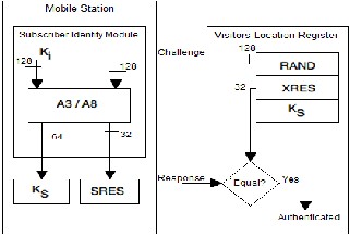
Figure: 2 [2]
At the time of call initialization phase, the VLR determine to substantiate a subscriber. It invocates substantiation criterion from HLR (Home Location Register). The HLR then invocates this criterion from the AuC (Authentication
Centre). A 128 bit random number (RAND) and the mobile key Ki is generated by A3 and A8 algorithms. These algorithms come under the AuC (authentication center). The algorithm A3 and A5 produces 32 bit signed Response (SRES) and Cipher Key (Kc).
This substantiation triad (RAND + Kc + SRES) is forwarded to the corresponding base transceiver station in which the mobile is positioned. The base transceiver station
exonerates a corroboration test: BTS passes a RAND to the mobile.
The mobile receives RAND and then passes to the SIM
card.
The SIM card forwards RAND to A3 and A8 with the copy of Ki.
The SIM card’s A3 Algorithm takes RAND and Ki to generate 32 bit response that is SRES which is then passed to the network.
The Cipher key (Kc) is generated by A8 algorithm which uses RAND and Ki.
Both the SRES is compared and if matched then the challenge is accepted. VLR carries out his authentication process.
Then communication can take place.
The security can be enhanced by storing all the keys and algorithms in home networks. The AuC does not impart the keys and algorithms and so it is not possible to ambush on the GSM networks. A GSM network allows different algorithms by different service provider on different networks because for authentication it only requires Kc and RAND same as the current base transceiver station has. The entire authentication is done by home networks and not by the roaming site or BTS. The A5 is the only algorithm which is common and encrypts the wireless communication (in mobile systems), the actual traffic. The A5 algorithm is used to encrypt the data (voice) on the air between the MS (mobile station) and the BTS (base transceiver station).
The basic working of authentication procedure when the mobile is started, using A3 and A8 is shown in the figure 3 below,
IJSER © 2014 http://www.ijser.org
International Journal of Scientific & Engineering Research, Volume 5, Issue 7, July-2014 155
ISSN 2229-5518
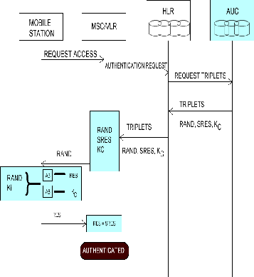

Figure: 4
These values are given to the SIM by mobile station and
SIM calculates SRES and Kc as shown in the figure 5 .
Figure: 3
The authentication processes as shown in above diagram 3, abbreviation are as follows,
MSC – Mobile Switching Center. AUC – Authentication Center. HLR – Home Location Register.
VLR – Visitors location Register.
RAND – Random number. RES – Response.
SRES – Signed Response.
Kc – Cipher Key.
The authentication center (AUC) has RAND and Ki (shown in figure 4), it which is passed to HLR and in turn to mobile station.
Figure: 5
This SRES and Kc is then sending back to MSC/VLR which checks for the equality, if matches then it’s authenticate otherwise it rejects.
Once the SRES and Kc is generated it is send to A5 for providing confidentiality to the call in progress.
The A5 algorithm helps to encrypt the data i.e. the communication channel and communicates with the BTS. The A5 algorithm is in the mobile equipment and not in the SIM card. The SIM only consists of A3 and A8 which produces Kc that act as input into Algorithm A5.
IJSER © 2014 http://www.ijser.org
International Journal of Scientific & Engineering Research, Volume 5, Issue 7, July-2014 156
ISSN 2229-5518

Thus this step takes total of 22 clock cycles
Step 4: registers are clocked 100 times with irregular clocking.
Irregular clocking also called as stop/ go clocking is determined by the registers. The respective registers agree with the majority between the three register bits and the register possessing the majority bit is clocked.
Figure: 6
Step 5: now initialization of register is completed. Again registers are clocked 228 times with irregular clocking procedure. The output of the registers is XoRed to produce
228 bits long keystream (The LSB’s of three registers are
XoRed for each shift). Thus 228 bits keystream is obtained.
Step 6: The keystream produced is now XoRed with the plain text to generate a cipher text.
To cipher another set of data frame, the same procedure is
The GSM attainment consists of algorithms which are used
for data encryption and provides authentication. The
encryption algorithms A5/1 and A5/2 are based on this standard, where encryption algorithm A5/1 was used within Europe and in many other countries. The algorithm A5/2 was made for better security but eventually found out that the strength of encryption was weak than the previous version i.e. A5/1. The designs were disclosed in 1999 with the help of reverse engineering although the internal matter of algorithms was kept secret.
The procedure of A5/1 is as follows:
Step1: Initially all Three Linear Feedback shift registers
(LFSR’s) are defines to zero i.e. R1=R2=R3=0
LFSR 1: length = 19 bits, clocking bit = 8, tapped bits = 13,
16, 17 and 18
LFSR 2: length = 22 bits; clocking bit = 10; tapped bits = 20,
21.
LFSR 3: length = 23 bits; clocking bit = 10; tapped bits = 7,
20, 21 and 22
Step2: Regular Clocking helps to achieve registers to clock
64 times. The session key of 64 bits is XoRed in parallel with
the LSB’s of the three registers and is given as feedback to
the registers.
Thus this step taking total of 64 clock cycles
Step 3: registers are clocked 22 times by XoRing the 22 bits Initial Vector/ frame counter with the LSB’s of the register and given as feedback to the registers respectively.
followed using the same session key but with the frame counter/ Initial Vector increased by a count of one. By re- authentication of mobile device the session key changes.
Just like A5/1 this too is a weakened stream cipher used in GSM. The two inputs at the disposal of A5/2 are a 64 bit key Kc (generated by A8) and a 22 bit openly known initial value called ‘F’. To understand the working of this algorithm we need to draw attention towards its internal circuitry. Unlike A5/1, this cipher has four maximal lengths Linear Feedback Shift Register (LFSRs) namely W, X, Y, and Z of varying lengths i.e. 19 bit, 22 bit, 23 bit and 17 bit respectively.
The registers are loaded with the two inputs Kc and F to
initiate the key stream process. This initial phase is known
as the key setup and comprises of 4 stages. The setup in all
the registers occurs in a linear pattern except at some locations where the bit is over ridden by 1.
The following is a list of the stages in the order of their occurrence
1. Set W=0, X=0, Y=0 and Z=0
2. Initially clock all registers using Kc i.e. EXOR all the bits
3. Next clock all the registers using F
4. Override bits W[15],X[16],Y[18], Z[10] to 1
After the initialization phase registers W, X, Y are clocked
according to the values in register of Z. The 3 bits which
decide the clocking of W, X, Y are Z [10], Z [3] and Z [7] respectively. These bits are run through a majority function whose outcome decides the clocking of W, X, Y, E.g. the three bits can be 1, 0, 1 or 1, 1, 1. In either case the output of the majority function would be 1. Now depending on which bit satisfies the majority function the corresponding register is clocked, E.g. for 1, 0, 1 registers W and Z are clocked. In other words the bits in these registers are right
IJSER © 2014 http://www.ijser.org
International Journal of Scientific & Engineering Research, Volume 5, Issue 7, July-2014 157
ISSN 2229-5518
shifted by one, eliminating the right most bit. Further these clocked registers obtain values of 3 bits to calculate the majority function, which is then EX-ORED with the right most bit. Hence the final output (1bit) would be an EXOR of Majority functions and the right most bit of each register. The output bit (1 bit) is obtained at the end of each cycle, which is EX-ORED with the data to obtain a keystream. So at the end of each cycle all that we obtain is a single bit which could be either used to encrypt or decrypt.
In A5/2 the initial 99 outcomes are discarded and the
following 228 bits are used as output keystream. The 228 bit
output stream is split into 2 halves one for encrypting the
link from network to phone and the following half to
encrypt from phone to network.
Both the algorithm uses Kasumi structure. A5/3 has 5 components of Kasumi.
Kasumi used here is in output feedback mode giving output of blocks of 64 bits of keys. Hence it can be said as
64 bits block cipher.
This cipher has 8 rounds consisting of Feistal structure.
Each round consist in itself two functions, say F0 and FL.
F0 itself consist of three rounds 32 bits of Feistal structure
(FI).
FL mixes the data with a 32 bits keyword.
As in 8 rounds in even rounds FL is arranged first and in
odd rounds FO is arranged first.
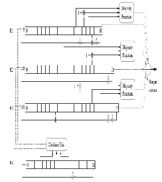
Figure: 7
These algorithms are used for signaling protection in order to encrypt the information’s such as a telephone number, the user data, voice signals etc. The same cipher algorithm is used named Kasumi, except that A5/3 uses 64 bits and A5/4 uses 128 bits of cipher key. That is there is variation only in the cipher key length.
The two inputs to the algorithm are the cipher key which can be of parameterized size (varying from 64 to 128 bits) and a COUNT of 22 bits. The output is two blocks of 114 bits used for encryption and decryption purposes respectively.
KASUMI ALGORITHM (A5/3):
The figure 7 shows the detailed version of signaling in the call initialization phase. The sequence diagram here explains the sequencing of signals.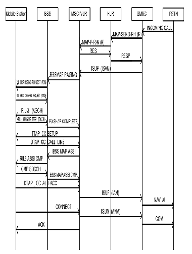
Figure: 8
IJSER © 2014 http://www.ijser.org
International Journal of Scientific & Engineering Research, Volume 5, Issue 7, July-2014 158
ISSN 2229-5518
The A3 and A8 algorithm resides in the SIM which can cause security issues; by cloning the SIM it is possible to get all the call and messages traced from the respective SIM number. Also by using the technology of mobile, attacker can decode the algorithm’s and can attack on provider’s network.
Hence, all cell phone should have all the details of the security algorithm instead in SIM. Even SIM card gets scratches when removed sometimes from the phone and re- inserted, which leads to network unavailability.
The phone should be fabricated in a way in which SIM can be fixed by the network provider but cannot be easily removed by the end customers. Also, the position of the SIM should be safe enough if the phone is lost or damaged.
The procedure for the call is simple, but the complications for the handshaking signals are shown and how it authenticates the call. A5 algorithm provides the confidentiality to the call which helps to provide better security to ongoing call between customers wirelessly. We have seen the detailed procedure and found out the different signals which are used.
[1]http://www.mobileworld.org/gsm_faq_03.html
[2]http://www.emsec.rub.de/media/crypto/attachments/
files/2010/04/da_gendrullis.pdf
[3]http://www.ni69.info/documents/engineering/gsm/A
52HackTool.pdf
[4]http://gsmsecurity.blogspot.in/2009/05/a53-or-
kasumi-encryption.html
[5]http://www.wacong.org/wac2006/allpapers/ifmip/if mip_196.pdf
[6] http://www.teletopix.org/gsm/what-is-hlr-and-vlr- and-its-function-in-gsm/
[7]http://www.isrc.rhul.ac.uk/useca/OtherPublications/3
G_UMTS%20Security.pdf
[8]http://www.gsma.com/technicalprojects/fraud-
security/security-algorithms
[9]http://www.izmf.de/en/content/how-does-
transmission-mobile-communication-work
[10]Information Network Security –Mark stamp- deven
shah
IJSER © 2014 http://www.ijser.org