International Journal of Scientific & Engineering Research, Volume 2, Issue 11, November-2011 1
ISSN 2229-5518
GSM Based Smart Data Logger System
K. Immanuvel Arokia James, M. Jagabar Sathik, M. Praveen
—————————— ——————————
he Overall process of our project gives a real time data entry and also gives responding on time infor- mation to the preferred person. Whenever we need the information we can collect it from the database of the device. Our proposed project was mainly based on GSM
networks and microcontroller.
This application can be implemented for all sorts of insti- tutions, factories, industries. Proper operation can be achieved through this project. The advantage of our project is used to eliminate manual checking and opera- tion. It also used to maintain the time consciousness.
Two types of classical methods,(i) The staff monitoring will be more manual work to maintain the monthly re- port and more difficult for instant update about the pres- ence of staff and it will give more manual work as well as wastage of papers. (ii) By using the Finger Print method we need a PC to get an update of present employee at- tendance, suppose the PC corrupted the database will destroy. To avoid this, we have designed new device to overcome the above said problems.
————————————————
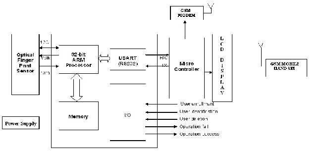
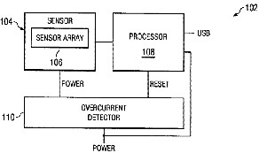
Our Proposing idea for on time staff entry report is mainly based on GSM networks and Microcontroller. In my proposed system we have GSM module used to trans- ferring the message through Network, Finger Print to check whether the concern faculty entered the class room or not. External Memory slot used to maintain the data- base.
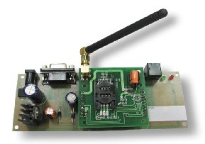
The designed modular kit contains GSM network for Wireless communication and USB slot is used for neg- lecting computer and other devices. The only wire is for power supply.
The designed device will intimate through SMS to the concern faculty before class time. Once the faculty entered the class room they should give finger print access.
If staff not entered in time the device will send the SMS to higher authorities on staff not present in a class and also it will keep the database about staff entry time, name and altered staff details. The concern faculty cannot move from the class room until the class time is complete. Whenever we need a report we can collect data from the database of device through Memory Slot.
Suppose the concern faculty not presented to the institution. In generally any faculty can alter the classes, but in our proposed system the only particular class staffs can alter the class, if fail it will inform to the higher au- thorities.
The following details we can read from the data- base:
The number of class’s calculation per subject
The faculty absentee’s details
The alter faculty details
Class entry time
Exit time.
IJSER © 2011
International Journal of Scientific & Engineering Research, Volume 2, Issue 11, November-2011 2
ISSN 2229-5518
BLOCK DIAGRAM
This document contains device specific information. Addi- tional information may be found in the PICmicro Mid-Range Reference Manual (DS33023), which may be obtained from your local Microchip Sales Representative or downloaded from the Microchip website. The Reference Manual should be considered a complementary document to this data sheet, and is highly recommended reading.
The various entities in the GSM network are connected to one another through signaling networks. Signaling is used for example, for subscriber mobility, subscriber registration, call establishment etc. The connections to the various entities are known as ‘reference points’. Examples include: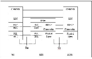
• A interface – the connection between MSC and BSC;
• Abis interface – the connection between BSC and BTS;
• D interface – the connection between MSC and HLR;
• Um interface – the radio connection between MS and BTS.
Various signaling protocols are used over the reference points. Some of these protocols for GSM are the following:
• Mobile application part (MAP) – MAP is used for call con- trol, subscriber registration, short message service, etc.; MAP is used over many of the GSM network interfaces;
• Base station system application part (BSSAP) – BSSAP is used
over the A interface;
• Direct transfer application part (DTAP) – DTAP is used be- tween MS and MSC; DTAP is carried over the Abis and the A interface. DTAP is specified in GSM TS 04.08.
• ISDN user part (ISUP) – ISUP is the protocol for establish-
ing and releasing circuit switched calls. ISUP is also used in landline Integrated Services Digital Network (ISDN).
A circuit is the data channel that is established be- tween two users in the network. Within ISDN, the data channel is generally a 64 kbit/s channel. The circuit is used for the transfer of the encoded speech or other data. ISUP is specified in ITU-T Q.763.
When it comes to call establishment, GSM makes a distinction between signaling and payload.
Signaling refers to the exchange of information for call set up; payload refers to the data that is transferred within a call, i.e. voice, video, fax etc.
For a mobile terminated GSM call, the signaling consists of exchange of MAP messages between GMSC, HLR and visited MSC (VMSC). The payload is transferred by the ISUP connection between GMSC and VMSC.
It is a continual aim to optimize the payload trans- fer through the network, as payload transfer has a direct cost aspect associated with it. Some network services are de- signed to optimize the payload transfer. One example is op- timal routing.
IJSER © 2011
International Journal of Scientific & Engineering Research, Volume 2, Issue 11, November-2011 3
ISSN 2229-5518
The GSM network consists mainly of the fol- lowing functional parts:
• MSC – the mobile service switching centre (MSC) is the core switching entity in the network. The MSC is connected to the radio access network (RAN); the RAN is formed by the BSCs and BTSs within the Public Land Mobile Network (PLMN). Users of the GSM network are registered with an MSC; all calls to and from the user are controlled by the MSC. A GSM network has one or more MSCs, geographical- ly distributed.
• VLR – the visitor location register (VLR) contains subscrib- er data for subscribers registered in an MSC. Every MSC contains a VLR. Although MSC and VLR are individually addressable, they are always contained in one integrated node.
• GMSC – The Gateway MSC (GMSC) is the switching entity that controls mobile terminating calls. When a call is estab- lished towards a GSM subscriber, a GMSC contacts the HLR of that subscriber, to obtain the address of the MSC where that subscriber is currently registered. That MSC address is used to route the call to that subscriber.
• HLR –The Home Location Register (HLR) is the database that contains a subscription record for each subscriber of the network. A GSM subscriber is normally associated with one particular HLR. The HLR is responsible for the sending of subscription data to the VLR (during registration) or GMSC (during mobile terminating call handling).
• CN – The Core Network (CN) consists of, amongst other things, MSC(s), GMSC(s) and HLR(s). These entities are the main components for call handling and subscriber manage- ment. Other main entities in the CN are the equipment iden- tification register (EIR) and authentication centre (AUC). CAMEL has no interaction with the EIR and AUC; hence EIR and AUC are not further discussed.
• BSS – The Base Station System (BSS) is composed of one or more base station controllers (BSC) and one or more base transceiver stations (BTS). The BTS contains one or more
transceivers (TRX). The TRX is responsible for radio signal
transmission and reception. BTS and BSC are connected through the Abis interface. The BSS is connected to the MSC through the A interface.
• MS – the mobile station (MS) is the GSM handset. The structure of the MS will be described in more detail in a next section. A GSM network is a public land mobile network (PLMN). Other types of PLMN are the time division mul- tiple access (TDMA) network or code division multiple access (CDMA) network. GSM
Uses the following sub-division of the PLMN:
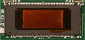
The Fujitsu SPF200-USB is an all-in-one USB device. Simply connect it to your USB cable and you have a working fingerprint sensor.
The SPF200-USB is ideal for integrating into devices
where USB is the communication interface such as computer peripherals and embedded applications.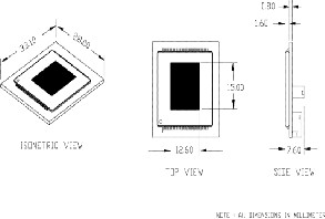
Mount the SPF200-USB into your device and you have a completed product without going through the ex- pense of board layout and debug. Users will no longer be required to remember and enter cumbersome passwords or PIN codes.
Fingerprint authentication provides a reliable, quick and user friendly alternative to passwords. The SPF200-USB fingerprint sensor has the USB 1.1 controller logic built right into the sensor, no external hardware is required. Merely plug the sensor into the USB cable, the power and data communications is managed by the USB protocol. The Fujit- su SPF200-USB fingerprint sensor quickly captures the im- age of the fingerprint, analyzes it and compares it to a pre-
IJSER © 2011
International Journal of Scientific & Engineering Research, Volume 2, Issue 11, November-2011 4
ISSN 2229-5518
viously registered fingerprint template. | 4. | Breaking into Embedded – Jack G.Gansle. |
The Fujitsu SPF200- USB fingerprint sensor consists of a | 5. | Programming Embedded Systems – Micheal Bar. |
256 column x 300 row array of tiny metal electrodes. Each | 6. | A Survey of Technologies Philip D. Wasserman. |
electrode acts as one plate in a capacitor and the finger acts | 7. | USB Mass Storage Designing and Programming Devices |
as the second plate in a capacitor. A passivation layer on the | and Embedded Hosts-Jan Axelson |
surface of the device forms a tough outer shell, protecting the device from abrasion, chemicals, moisture and other forms of damage. The SPF200-USB is manufactured in stan- dard CMOS technology, a mature and cost effective manu- facturing method.
Operating Current: 18 milli amps
Standby Current: 500 micro amps
Fingerprint Sensor: MBF200
Operating Temperature: 0 to 60°C
Storage Temperature: -65 to 150°C and
Resolution: 500 DPI, 8-bit grayscale
This project mainly focuses the on time report entry and perfect to maintain the database of the particular em- ployee. Implementation of this project is simple and very economical. This application can be implemented for all sorts of institutions, factories, industries. Proper operation can be achieved through this project. The advantage of our project is used to eliminate manual checking and operation. It also used to maintain the time consciousness. Only the concerned staff can be altered. This project saves more ma- nual power and cost.
More supportive to the industries, factories, which im- proves their overall discipline performance (punctuali- ty).
Instant Feedback.
Easy way of getting database.
1. PIC Technologies, PIC Controller Operation guide –
David Benson.
2. Programming and customizing the PIC microcontroller
– Micheal predco.
3. Design with PIC microcontroller – John B.Peatman.
IJSER © 2011