International Journal of Scientific & Engineering Research, Volume 4, Issue 12, December-2013 1563
ISSN 2229-5518
Fuzzy control and performances amelioration of an electric vehicle drive train based on doubly fed induction machine
Rabah Babouri*, Kaci Ghedamsi, Djamal Aouzellag
Laboratory of Renewable Energy Mastery, University of Bejaia, Bejaia 06000, Algeria
* Corresponding author. Tel.: +213-556-463-120; fax: +0-000-000-0000.
E-mail address: rabah.babouri@yahoo.fr.
Abstract— The aim of this paper is to show advantages of integration of doubly fed induction machine (DFIM) controlled by fuzzy logic algorithm in an electric vehicle drive train. So the DFIM is powered by two bidirectional converter, and a fuzzy logic controller is designed to control the speed of pulling unit. These give the possibility to operate the machine over wide range of speed variation, for both applications: engine and recovery, while addressing the non-linearity problems of the system. Consequently, the power of the machine can reach twice its rated power, thus the power density is doubled. The latter is an important factor, because in embedded systems, the reduction of weight is very required, especially in the electrics vehicles case. Simulation work is carried out on the software MATLAB/Simulink and the results showed goodness in performances of the fuzzy control algorithm and the feeding structure applied to the DFIM.
Index Terms— DFIM; fuzzy logic; wide speed variation; Power density; PWM converters; battery; control of vehicles drive train.
1. Introduction
The environmental impact of energy production,
modulation control (PWM), these converters are both powered by a battery, which is a key element for development of
IJSER
conversion and final use is more and more influencing our life,
and the consensus about the necessity to limit carbon dioxide emissions is widely increasing [1][2]. The transportation sector is the most rapidly growing consumer of the world’s
energy, consuming 49% of the oil resources [3][4]. Electric
vehicles (EVs) can potentially play an important role in
transforming the transportation sector towards sustainability, public health and safety, because of it low level of environmental pollution, noise and availability of multiple renewable resources, such as solar energy[5]-[8].
Different kind of electric machines can be used in a drive train of an electric vehicle, the choice of the later depend on his dynamic performances, reliability and cost [9]-[11]. Literature shows the great interest shown in the double-fed induction machine (DFIM) for various applications: as a generator for wind energy and for certain industrial
applications, such as rolling and traction or maritime
electrical vehicles, namely the energy density is low and the
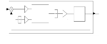
charge time very long [14]. In the drive train we use only one machine (DFIM) for the motorization of the vehicle, and for recovering energy during braking. The advantage of the power structure chosen is not only to operate the machine in a wide range of speed variation, but also to give to the machine the capacity to operate up to twice its rated power. So the power density is improved. Figure (1) illustrates the schematic diagram of the drive train:
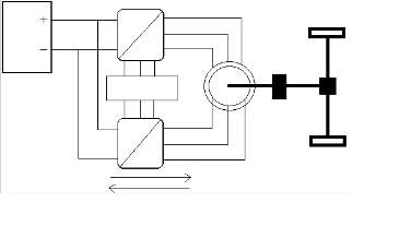
The ability of the DFIM to start with high torque makes possible the elimination of clutch and gearbox. The torque is the size dimensioning; therefore the machine must be heavier and bulky, so more expensive. The use of fixed ratio gearbox overcome these problems and allows to have a simple machine that can provide the required torque [12].
propulsion [12]. Indeed, most work on this machine have been the subject of the study of the structure where the stator is directly connected to the network and the rotor powered by a
Battery
DC
AC
DFIM
Gearbox
Wheel
power electronics converter. The advantage of this solution is
that the converter is sized at 30% of the rated power of the system and therefore the variation of speed limit near the speed of synchronization [13][14]. However, the objective of this work is to operate the DFIM in a wide range of speed variation, for application in a drive train of an electric vehicle,
using a non-linear algorithm based on fuzzy logic controllers
PWM control
DC
AC
Powers
Deffirential
Wheel
for the speed control of the latter. For this, the machine is connected through two power converters with pulse wide
Fig. 1. Representative diagram of the electric vehicle drive train
IJSER © 2013 http://www.ijser.org
International Journal of Scientific & Engineering Research, Volume 4, Issue 12, December-2013 1564
ISSN 2229-5518
The power electronic converters used for power transfer between the battery and the DFIM are sized at 100% of rated power of the machine, those are
In order to achieve good decoupling between the axes d and q, we define intermediate voltages as follows:
bidirectional converters with PWM control, they absorb power from the battery when the machine
𝑣𝑠𝑎 −
�

𝑀
𝐿𝑟

𝑀
𝑣𝑟𝑎 = 𝑣𝑡𝑠𝑎
(2)
operates as a motor and they provide to it when the
machine operates as a generator (braking).
𝑣𝑟𝑎 − 𝑣𝑠𝑎 = 𝑣𝑡𝑟𝑎
𝑠
𝑀
Semiconductors used depends on power level
passing converters; for low powers are used IGBT.
𝑣𝑠𝑠 −
�
𝐿𝑟

𝑀
𝑣𝑟𝑠 = 𝑣𝑡𝑠𝑠
(3)
For high power converters based on IGCT or GTO
semiconductors can be used. Variable-speed drives with a rated power up to 40MW (IGCT) or 100MW (GTO) have been installed. A disadvantage of these semiconductor types is their lower switching frequency, compared with IGBT’s [15].
The control of the drive train of an electric vehicle is very difficult, and this is due to the fact that

𝑣𝑟𝑠 − 𝑣𝑠𝑠 = 𝑣𝑡𝑟𝑠
𝑠
Coupling terms appear to compensate; 𝑃1𝑎 , 𝑃1𝑠 ,
𝑃2𝑎 , 𝑃2𝑠 , these expressions allow to obtain
relations between the intermediate voltages and
the stator and rotor currents in d or q axes. So:
𝑣𝑡𝑠𝑎 = 𝑅𝑠 (1 + 𝑆𝑇𝑠 𝜎)𝑖𝑠𝑎 + 𝑃1𝑎
⎪ 𝑣𝑡𝑠𝑠 = 𝑅𝑠 (1 + 𝑆𝑇𝑠 𝜎)𝑖𝑠𝑠 + 𝑃1𝑠
its dynamics is nonlinear due to the state trajectory
that is variable in general, and also the high nonlinearity of the electric machines used, which has the coupling terms between the stator and rotor and
𝑣𝑡𝑟𝑎 = 𝑅𝑟 (1 + 𝑆𝑇𝑟 𝜎)𝑖𝑟𝑎 + 𝑃2𝑎
⎪𝑣𝑡𝑟𝑠 = 𝑅𝑟 (1 + 𝑆𝑇𝑟 𝜎)𝑖𝑟𝑠 + 𝑃2𝑠
With:
T =L /R : stator electrical time constant;
(4)
IJSER
the variation of these parameters with temperature [16]. So in this work, a non linear controller based on fuzzy logic is developed for the speed control of the vehicle.
s s s
Tr = Lr / Rr : rotor electrical time constant;
σ = (1-M2/ (Ls .Lr )): dispersion coefficient.
The coupling terms can be expressed as follows:
An objective of fuzzy logic has been to make computers think like people. Fuzzy logic can deal
with the vagueness intrinsic to human thinking and

𝑀
1𝑎
𝑟

⎪𝑃 = − 𝑀
1𝑠 𝐿𝑟


𝑀

𝑅 𝑖 − 𝜔 𝑐 + 𝜔 𝑀
𝑟 𝑟𝑎 𝑠 𝑠𝑠 𝐿𝑟

𝑅 𝑖 + 𝜔 𝑐 − 𝜔 𝑀
𝑟 𝑟𝑠 𝑠 𝑠𝑎 𝐿𝑟
𝑀
𝑐𝑟𝑠
𝑐𝑟𝑎
(5)
natural language and recognizes that its nature is
⎨ 𝑃2𝑎 = −

𝑠
𝑅𝑠 𝑖𝑠𝑎 + 𝜔𝑠

𝑠
𝑐𝑠𝑠 − 𝜔𝑐𝑟𝑠
different from randomness. Using fuzzy logic
algorithms could enable machines to understand and
⎪
⎩𝑃2𝑎 = −
𝑀
𝐿𝑠
𝑅𝑠 𝑖𝑠𝑠 − 𝜔𝑠
𝑀
𝐿𝑠
𝑐𝑠𝑎 + 𝜔𝑐𝑟𝑎
respond to vague human concepts such as hot, cold,
large, small, etc. It also could provide a relatively
From system of equations (4), the transfer’s
functions following are obtained:
1
simple approach to reach definite conclusions from imprecise information [17][18]. The basic
⎧𝑇𝑠𝑎 = 𝑉
⎪

𝐼𝑠𝑑
𝑡𝑠𝑑−𝑃
𝐼𝑠𝑞
1𝑑

= �𝑅𝑠
1−𝑆𝑇𝑠𝜎
1�𝑅
configuration of a fuzzy-logic controller is composed

⎪ 𝑇𝑠𝑠 =
𝑉𝑡𝑠𝑞 −𝑃1𝑞

= 𝑠
1−𝑆𝑇𝑠 𝜎
(6)
of four parts: the fuzzifier, the knowledge base, the
⎨ 𝑅


𝑇 = 𝐼𝑟𝑑
� 𝑟
inference engine and the defuzzifier [19][20].
⎪ 𝑟𝑎
=

𝑉𝑡𝑟𝑑−𝑃2𝑑 1−𝑆𝑇𝑟𝜎
2. DFIM model
⎪ 𝐼𝑟𝑞
�𝑅𝑟
Two-phase equivalent model of the DFIM
represented in the reference (dq) linked to the rotating field is given as follows [21][22]:
⎧𝑣𝑠𝑎 = 𝑅𝑠 𝑖𝑠𝑎 + 𝑆𝑐𝑠𝑎 − 𝜔𝑠 𝑐𝑠𝑠
⎩ 𝑇𝑟𝑠 = 𝑉𝑡𝑟𝑞 −𝑃2𝑞 = 1−𝑆𝑇𝑟𝜎
3. Converters model
The matrix giving the model of powers electronics converters used is expressed as follows:
𝑣𝑠𝑠 = 𝑅𝑠 𝑖𝑠𝑠 + 𝑆𝑐𝑠𝑠 + 𝜔𝑠 𝑐𝑠𝑎
(1)
𝑣𝑎𝑠

1
1 −1 0
𝑆𝑎
⎨𝑣𝑟𝑎 = 𝑅𝑟 𝑖𝑟𝑎 + 𝑆𝑐𝑟𝑎 − (𝜔𝑠 − 𝜔)𝑐𝑟𝑠
�𝑣𝑏𝑠 � = 𝑈0 � 0 1 −1� �𝑆𝑏 � (7)
⎩ 𝑣𝑟𝑠 = 𝑅𝑟 𝑖𝑟𝑠 + 𝑆𝑐𝑟𝑠 + (𝜔𝑠 − 𝜔)𝑐𝑟𝑎
𝑣𝑐𝑠
−1 0 1
𝑆𝑐
With S: Laplace Operator
4. Battery model
The model of battery used for application in electric vehicle should have the specifications as follows [23]:
IJSER © 2013 http://www.ijser.org
International Journal of Scientific & Engineering Research, Volume 4, Issue 12, December-2013 1565
ISSN 2229-5518
- It should simulate the variation of the battery’s terminal voltage on certain load demand or current demand;
- It should be simple and require limited times for mathematical calculation and iteration;
- The model should be involved with as few as possible or none of the parameters that are related to the battery’s chemical process.
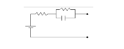
There have been many proposals battery model; one of this is the Thevenin equivalent circuit, shown in figure (2). It is a linear electrical battery model [24].
𝑅
Where g is the earth gravity and Mv is the total weight of the vehicle.
6. Vector control of the DFIM
A vector controlled doubly fed induction machine is an attractive solution for high restricted speed rang electric drive and generation application, it consists in guiding an electromagnetic flux of the DFIM along the axis d or q.[15] In our case we choose the direction of reference (d,q) according to the direct
stator flux vector 𝜙𝑠𝑎 , so the DFIM model in static
state will be simplified as follows:
𝑣𝑠𝑎 = 𝑅𝑠𝑎 𝑖𝑠𝑎
𝑅
𝑣0
0
𝐶0
𝑖𝑏
+
𝑣𝑏
-
⎧ 𝑣𝑠𝑠 = 𝑅𝑠 𝑖𝑠𝑠 + 𝜔𝑠 𝜙𝑠𝑎
⎨𝑣𝑟𝑎 = 𝑅𝑟 𝑖𝑟𝑎 − 𝜔𝑟 𝜙𝑟𝑠
⎩𝑣𝑟𝑠 = 𝑅𝑟 𝑖𝑟𝑠 + 𝜔𝑟 𝜙𝑟𝑎
Such as:
(14)
Fig. 2. Thevenin equivalent circuit of battery
𝑣𝑏 = 𝑣0 − 𝑣𝑐0 − 𝑅𝑖𝑏 (8)
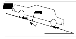
5. Vehicle Dynamics
𝜔𝑟 = 𝜔𝑠 − 𝜔 (15)
The magnetization of machine is assured by the rotor
direct current, so the stator current in the d axis is
taken to zero (𝑖𝑠𝑎 = 0 ). The current and voltage in
IJSER
Equation governing vehicle dynamics is given as
following [25]:

𝑇 = �𝐹 + 𝐹 + 𝐹 � 𝑟 + δ𝑀 𝑎𝑉𝑣 (9)
𝑎𝑡
𝐹𝑎𝑟𝑎
this line are then in phase:
𝑣𝑠𝑠 = 𝑣𝑠 and 𝑖𝑠𝑠 = 𝑖𝑠 (16)
In this case we obtain a unity power factor at the
stator, so the stator reactive power is zero Qs =
0.These simplifications lead to the electromagnetic torque expression:
𝑇𝑒𝑒 = 𝑝𝜙𝑠 𝑖𝑠𝑠 (17)
From the expressions of equations which have been
𝑉𝑣
𝐹𝑟
𝑀𝑣 g𝑐𝑐𝑐(𝛼)
𝑀𝑣 g𝑐𝑖𝑠(𝛼)
𝑀𝑣 g
𝐹𝑟 𝛼

established, we can draw a connection summary table setting the objectives of the control strategy with the references of action variables involved:
Objectifs References
Fig. 3. Various forces applied to the vehicle
𝜙𝑠𝑎 = 𝜙𝑠 = 𝜙𝑠𝑠 𝑖∗ = 𝜙𝑠𝑠
𝑟𝑎 𝑀
𝜙𝑠𝑠 = 0 𝑖 ∗ = − 𝐿𝑠 𝑖∗
𝐹𝑟 = 𝑃. 𝐶𝑟 (10)
𝑟𝑠
∗
𝑀 𝑠𝑠
𝑄𝑠 = 0, (𝑐𝑐𝑐𝑐 = 1) 𝑖𝑠𝑎 = 0
∗

𝐶 = 0,01 �1 + 𝑉𝑣 � (11)
100
Which 𝐶𝑟 is called the rolling resistance coefficient
𝑇𝑒𝑒 = 𝑇∗
∗
𝑠𝑠
𝑇𝑒𝑒
𝐾𝑇𝑒𝑒
and P is the normal load on the Wheel.
𝐹𝑤 = 0.5𝜌𝐴𝑓 𝐶𝑎 (𝑉𝑣 + 𝑉𝑤 )2 (12)
Where ρ is the air density, Af is the frontal area of the
vehicle, Cd is aerodynamic coefficient, Vv is the vehicle speed and Vw is the wind speed.
𝐹𝑔 = 𝑀𝑣 gsin(α) (13)
Table. 1. Control strategy applied to the DFIG model
7. Fuzzy speed control of the drive train
Fuzzy logic systems address the imprecision of the input and output variables directly by defining
them with fuzzy numbers (and fuzzy set) that can be
IJSER © 2013 http://www.ijser.org
International Journal of Scientific & Engineering Research, Volume 4, Issue 12, December-2013 1566
ISSN 2229-5518
expressed in linguistic terms (e.g., small, medium and large).
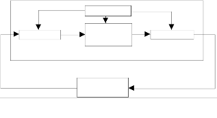
Knowledge base
Inference
The input of the fuzzy controller is the error and error variation of the rotational speed of the machine, the quantities concerned are noted E and dE successively, that are numerical values. The fuzzification interface transforms these numerical values into linguistic values.
Fuzzifier
Measure
engine
System
Defuzzifier
Control
Five fuzzy sets represented by membership functions are used for describe input and output values: large negative (LN); negative (N); zero (Z); positive (P); large positive (LP).
In this study a two-dimensional array is used. Entries
in the table (2) represent the fuzzy sets of input
Fig. 4. General diagram of fuzzy controller
The basic configuration of the FLC includes a fuzzy rule base, which consist of a collection of fuzzy IF-THEN rules [26].
A block diagram of a fuzzy control system is shown in Figure. 4. The fuzzy controller is composed of the following four elements [26]-[28]:

1. A rule-base (a set of If-Then rules), which contains
variables. The intersection of a column and a line shows the fuzzy set of the output variable defined by the rule.
a fuzzy logic quantification of the expert’s linguistic
description of how to achieve good control.
2. An inference mechanism (also called an “inference engine” or “fuzzy inference” module), which emulates the expert’s decision making in interpreting and ap- plying knowledge about how best to control the system.
3. A fuzzification interface, which converts controller inputs into information that the inference mechanism can easily use to activate and apply rules.
4. A defuzzification interface, which converts the
Table. 2. Rules table
8. Powers distribution
The distribution of stator and rotor active powers is a requirement in the control strategy to be applied. Indeed, this allows increasing the range of speed variation and the power density of the machine. Such as if the stator and rotor resistance windings terms are neglected, the following relationship is imposed:
conclusions of the inference mechanism into actual


|𝑃𝑠 | = |𝜔𝑠|
(18)
inputs for the process
|𝑃𝑟|
|𝜔𝑟|
The diagram showing the fuzzy logic control of the drive train speed of the vehicle is given in fig. 5.
Whith 𝐾1, 𝐾2, 𝐾3 are the adjustment factors
associated with the error, its variation and the
command.
Therefore, the stator and rotor active powers
distribution, involve the stator and rotor pulses distribution and vice versa.
Working with a slip s = -1 we obtain the following relationship:


𝜔𝑠−𝜔 = 𝜔𝑟 = −1 (19)
𝜔𝑠
𝜔𝑠
Ωt*
+-
K1
de K2
FLC
1
S K3
EVDT
Ωt So:
𝜔𝑠 = −𝜔𝑟 (20)
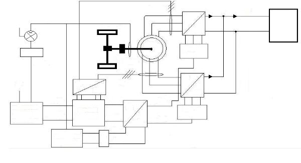
dt The diagram representing the complete system with
the control strategy applied is given by figure (6).
Fig. 5. Fuzzy control of drive train speed
IJSER © 2013 http://www.ijser.org
International Journal of Scientific & Engineering Research, Volume 4, Issue 12, December-2013 1567
ISSN 2229-5518
Ω* Wheel
+ Gearbox Ω
is_abc
AC is ib
DC
+
Battery
-
FLC
Tem*
Deffirential
Wheel
abc
ir_abc
DFIM
PWM
ir
AC
φ* dq
*
s _dq
DC
vs _abc
References currents calculation
Currents control
𝜔𝑠
dq
vr _dq
𝜃𝑠
abc
*
_abc
PWM
generator
Repartition of
pulsations
𝜔𝑟
1/s
𝜃𝑟
Fig. 6. Control diagram of the electric vehicle drive train
9. SimulationIresultsJand discussiSon ER
A fuzzy speed control with pulses repartition
(𝑐𝑙𝑖𝑝 = −1) is applied to the DFIM for a path of a
road with variable slopes. The overall system
simulation is performed on the MATLAB / Simulink, the following figures show the simulation results:
400
300
200
100
0
-100
-200
4000
3000
2000
3050
-300

0 2 4 6 8 t (s)
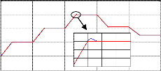
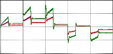
Fig. 9. Resistance, reference and electromagnetic
torque (N.m)
1000
3000
0
-1000
1
0.5
0
-0.5
2950
2900
2850
4.6 4.7 4.8 4.9 5

0 2 4 6 8 t (s)
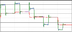
Fig. 7. DFIM speed and reference speed (rpm)
5
x 10
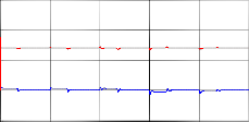
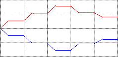
According to the simulation results, it was noted that the DFIM operates over a wide range of speed variation (twice the nominal speed), while following the reference imposed; consequence of the good performances of the fuzzy logic algorithm applied for the speed control of the pulling unity. The distribution of pulsations applied for the control of DFIM has allowed to have the distribution of stator and rotor actives powers (fig. 8.), however, there is a slight difference and this is due to the stator
resistance that is greater than the rotor resistance, and
-1
0 2 4 6 8 10
t (s)

Fig. 8. Stator, rotor and battery powers (W)
we note that the total power exchanged between the battery and DFIM equal to the sum of the stator and rotor actives powers.
IJSER © 2013 http://www.ijser.org
International Journal of Scientific & Engineering Research, Volume 4, Issue 12, December-2013 1568
ISSN 2229-5518
During the acceleration phase, figure (9) shows that the electromagnetic torque developed by the machine is far greater than the resistive torque imposed by the vehicle, and this is for overcome the total inertia for bring the vehicle to a highest speed, therefore the power supplied by the DFIM is greater than the power in the steady state, and for a rotational speed equal to twice the nominal speed, the power absorbed from the battery equal to twice of rated power of the machine. During deceleration (braking) or downhill, the electromagnetic torque becomes negative. Therefore the DFIM provides power for recharging the battery.
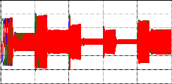
300
200
100
0
-100
-200
-300

100
50
0

0 2 4 6 8 10 t (s)
Fig. 13. Rotor currents (A)
1.5
1
0.5
-50
-100

3 3.01 3.02 3.03 3.04 3.05 t (s)
Fig. 14. Stator currents zoom (A)
0
-0.5
100
50
0 2 I4 J6 8 S10 ER

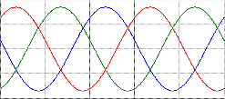
Fig. 10. Stator direct and quadrature flux (Wb) 0
-50
400
200
-100

3 3.01 3.02 3.03 3.04 3.05 t (s)
Fig. 15. Rotor currents zoom (A)
0 200
-200
150
-400

0 2 4 6 8 10 t (s)
Fig. 11. Stator and rotor pulsations (rd/s)
100
50
0
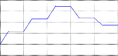
300
200
100
-50

0 2 4 6 8 10 t (s)
Fig. 16. Vehicle speed (km/h)
0
-100
-200
-300
0 2 4 6 8 10 t (s)

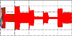
Fig. 12. Stator currents (A)
figures (12, 13), and their respective zoom are given
in figures (14, 15). Both figures have an identical shape, and same pulse for a given rotational speed
10. Conclusion
The aim of this work is to integrate DFIM in a drive train of an electric vehicle, and to show the
Figure (11) shows the pulsations shapes of the stator and rotor, the two pulsations values have equal amplitude and opposite sign justifying the pulsationsdistribution law applied to the DFIM. The
stator and rotor currents are shown respectively in
performances of fuzzy logic control used for the speed control of this vehicle. Indeed, the simulation results obtained show that the DFIM can operate over wide range of speed variation, with following
imposed speed reference. The first advantage of this
IJSER © 2013 http://www.ijser.org
International Journal of Scientific & Engineering Research, Volume 4, Issue 12, December-2013 1569
ISSN 2229-5518
system is to replace the gearbox with a speed reducer, and remove the clutch, which are very complicated and expensive systems. The second advantage is that the power of the machine rises up twice of its rated power providing an increase of its power density, which is an important factor in embedded systems. The third advantage is the use of fuzzy logic algorithm for the control of the pulling unit. So the driver controls the vehicle perfectly, whatever the exterior disturbances and parametric variation of the machine.
Seen these benefits, the DFIM with the control strategy applied is a very good alternative for use in a drive train of an electric vehicles.
Nomenclature

𝐴𝑓: Frontal area of the vehicle
𝐶0: Battery capacity
𝐶𝑎 : Aerodynamics coefficient

𝛺∗: Reference speed
𝜌: Air density
References
[1]: Stefano Campanari, Giampaolo Manzolini, Fernando Garcia de la Iglesia. Enegy analysis of electric vehicles using battery or fuel cells through well-to-weel driving cycle simulation. Journal of power Sources 186 (2009) 464-477.
[2]: Freng-kuag. Wu, T.-J. Yeh, Chun-Feng Huang. Motor control and torque coordination of an electric vehicle actuate by tow in wheel motors. Mechatronic 23 (2013) 46-60.
[3]: Shaik Amjad, S. Neelakrishnan, R. Rudramoorthy. Review of design considerations and technological challenges for successful development and deployment of plug-in hybrid electric vehicles. Renewable and Sustainable Energy Reviews
14 (2010) 1104-1110.
[4]: Martin Weiss, Martin K.Potel, Martin Junginear, Adolfo Perujo. On electrification of road transportation and price forecasts for hybrid-electric and battery-electric vehicles. Energy Policy 48 (2012) 374-393.
[5]: Reed T. Doucette, MalcolmD. Mc Culloch. Modeling the prospects of plug-in hybrid electric vehicles to reduce CO 2 emissions. Applied Energy 88 (2011) 2315-2323.
[6]: Karsten Hedegaard, Hans Rawn, Nina Juul, Peter
Meibom. Effects of electric vehicles on power systems in
IJSER
𝐹𝑎𝑟𝑎 : Aerodynamic force
𝐹𝑔 : Gravitational strength
𝐹𝑟 : rolling force
𝑔: Earth gravity
𝑖𝑏 : Battery current
𝑖𝑠𝑎 , 𝑖𝑠𝑠 , 𝑖𝑟𝑎 , 𝑖𝑟𝑠 : Direct and quadrature of stator
and rotor currents
𝐿𝑠 ,𝐿𝑟 : Stator and rotor inductances
𝑀: Mutual inductance
𝑀𝑣 : Vehicle total weight
𝑅: Battery resistance
𝑟𝑎 : Wheels radius
𝑅𝑠 ,𝑅𝑟 : Stator and rotor resistances
𝑇𝑒𝑒 : Electromagnetic torque
𝑇∗ : Reference torque
𝑣0: Open circuit voltage
𝑣𝑏 : Battery voltage
𝑣𝑐0 : The double layer capacity voltage
𝑣𝑠𝑎 , 𝑣𝑠𝑠 , 𝑣𝑟𝑎 , 𝑣𝑟𝑠 : Direct and quadrature of stator
and rotor voltages
𝑉𝑣 : Vehicle speed
𝑉𝑤 : Wind speed
𝑐𝑠𝑎 , 𝑐𝑠𝑠 , 𝑐𝑟𝑎 , 𝑐𝑟𝑠 : Direct and quadrature of stator
and rotor flux
𝜔𝑠 , 𝜔𝑟 : Stator and rotor pulsations
𝛺: DFIM speed
northern Europe. Energy 48 (2012) 356-368.
[7]: Niamh O’Cannel, Qiuwei Wu, Jacob ϕstergaard, Arne Hejde Nielsen, Seung Tae Cha, Yi Ding. Day-ahead tariffs for the alleviation of distribution grid congestion from electric vehicles. Electric Power Systems Research 92 (2012) 106-114. [8]: Zhang Guirong, Zhang Henghai, Li Houyu. The driving control of pure electric vehicle. Procidia Environmental Sciences. 10 (2011) 433-438.
[9]: Fridrik Roos, Hans Johansson, Jan Wikander. Optimal selection of motor and gearhead in mechatronic applications. Mechatronics 16 (2006) 63-72.
[10]: R.Campagne, L-A.Dessaint, H.Fortin-Blanchette. Real time simulation of electrical drive. Mathematique and computers in simulation 63 (2003), 173-181.
[11]: A. Chaiba, R. Abdessemed, M.L. Bendaas et A. Dendouga. Control of torque and unity stator side power factor of the doubly-fed induction generator. Conférence sur le génie électrique CGE’04, EMP Alger, 2005.
[12] : R. Babouri, D. Aouzellag, K. Ghedamsi. Introduction of doubly fed induction machine in an electric vehicle. Energy Procedia 36 (2013) 1076-1084.
[13]:Ghania Mouna, Chaffaa, Khirddine, Benmahammed Khier. Adaptive type-2 fuzzy control for induction motor. Second international conference on electrical systems, ICES’06, 2006, Oum El Bouaghi, Algeria.
[14]: Lota Gidwani, Harpal Tiwani, R.C.Bansal. Improving power quality of wind energy conversion system with unconventional power electronic interface. Electrical Power and Energy Systems 44 (2013) 445-453.
[15]: Joris Soens, Karel de Brabondere, Johan Driesen, Ronnie Belmans. Doubly fed induction machine: Operating regions and dynamique simulation. EPE 2003-Toulouse, ISBN:90-
75815-07-7.
IJSER © 2013 http://www.ijser.org
International Journal of Scientific & Engineering Research, Volume 4, Issue 12, December-2013 1570
ISSN 2229-5518
[16]: Hamid Khayyam, Saeid Nahavandi, Sam Davis. Adaptative cruise control look-ahead system for energy management of vehicles. Expert Systems With Application. 39 (2012) 3874-3885.
[17]: Ahmed M. Ibrahim. Fuzzy logic for embedded systems applications. Elsevier science (USA) 2004, ISBN: 0-7506-
7699-X.
[18]: Mariam Shahriari Kahkeshi, Farid Sheikholeslan, Maryam Zekri. Design of adaptive fuzzy walvelet neural sliding mode controller for uncertain nonlinear systems. ISA transaction 52 (2013) 342-350.
[19]: A.L. Elshafei, M.A. Azzoz. Adaptative fuzzy regulation of the DC-bus capacitor voltage in a wind energy conversion system (WECS). Expert System With Application 38 (2011)
5500-5506.
[20]: Moez Allouch, Mohamed Chaabane, Mansour Souissi and Driss Mehdi. Fuzzy tracking control for indirect field oriented induction machine using integral action performance. IETE Journal of Research/Vol 57/Issue 5/Sep-Oct 2011.
[21] : C. Belfedal, S. Gherbi, M. Sedraoui, S. Moreau, G. Champenois, T. Allaoui, M.A. Denai. Robust control of doubly feed induction generator for stand-alons applications. Electric Power Systems Research 80 (2010) 230–239.
[22]: S.Persada, A.Tilli, A.Tonielli. Robust active-reactive powers control of a doubly fed induction machine. proc. of IEEE-IECON’98, Aachen, Germany, Sep.1998.pp.1621-1625. [23]: Nang Janping, ChenQuanshi, Cao Binggong. Support vector machine based battery model for electric vehicles. Xi’an Jiaotong University, Xi’an 710049, PR, China.
[24]: Ziyad M. Salameb, Margaret A. Casacca, William A. Lynch. A mathematical model for lead-acid battery. IEEE Transaction on Energy Conversion, Vol.7, No.1, 1992.
[25]: Siavash Zoroofi. Modeling and simulation of vehicular power systems. Master’s thesis in Electric Power Engineering, Chalmers University of Technology, 2008.
[26]: Tsung-Chin Lin, Chia-Hoa Kuo. 𝐻∞ synchronization of
uncertain fractional order chaotic systems: Adaptive fuzzy
approach. ISA Transaction 50 (2011) 548-556.
[27]: Kivin M. Passino, Stephen Yurkovich. Fuzzy control. Addison Wesley longman Inc 1998. ISBN 0-201-18074-X.
[28]: Saptarshi Das, Indranil Pan, Shantanu Das. Performance comparison of optimal fractional order hybrid fuzzy PID controllers for handing oscillatory fractional order processes with
dead time. ISA Transaction 52 (2013) 550-566.
IJSER © 2013 http://www.ijser.org